Sign In
Upload
Download
Table of Contents
Contents
Add to my manuals
Delete from my manuals
Share
URL of this page:
HTML Link:
Bookmark this page
Add
Manual will be automatically added to "My Manuals"
Print this page
×
Bookmark added
×
Added to my manuals
Manuals
Brands
Elvox Manuals
Intercom System
Vimar 40540
Use manual
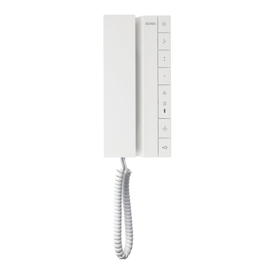
Elvox Vimar 40540 Use Manual
Voxie due fili plus handset entryphone
Hide thumbs
1
Table Of Contents
2
3
4
5
6
7
8
9
10
11
12
13
14
15
16
17
18
19
20
21
22
23
24
25
26
27
28
29
30
31
32
33
34
35
36
37
38
39
40
page
of
40
Go
/
40
Contents
Table of Contents
Bookmarks
Table of Contents
Table of Contents
General Information
Warnings and Advice
Technical Functions
Technical Data
Dimensional Data
Handset Entryphone 40540 - 40542 - 40540.D
Keys and Status Leds (Front View)
Internal View (Entryphone Open)
Hands-Free Entryphone 40547
Keys and Status Leds (Front View)
Internal View (Entryphone Open)
Installation
Wiring Diagrams
Operation
Answering a Call
Lock Release
Calling an Indoor Station (Intercom)
Calling a Reception Switchboard
Professional Firm" Function, for Automatic Lock Release
General" Apartment Intercom Call (Only for 40542 and 40547 by Default)
Paging": Sending a One-Way Public Paging Announcement to Other Hands-Free Devices in the same Group (Only for 40542 and 40547)
Alert" Function with Dedicated Input on Terminals AL-M (Only for 40542 and 40547)
Simplified" Programming Via Entryphone Push Buttons
Identification Code Programming
Secondary Identification Code Programming
Programming Push Buttons for Intercom Calls (Excluding the Lock Release Button)
Programming the Self-Start Push Button to a Specific Entrance Panel (Excluding the Lock Release Button)
Programming the Lock Release Button of a Specific Entrance Panel (Excluding the Lock Release Button)
Restoring Default Values of Push Buttons
Deleting All Programmed Settings
Configurations
Dip Switch Configuration Mode
Firmware Updating
Rules - Regulatory Compliance
Advertisement
Quick Links
1
Wiring Diagrams
2
Dip Switch Configuration Mode
Download this manual
Use and Configuration Manual
Voxie
40540 - 40542 - 40540.D
Voxie Due Fili Plus handset entryphone
40547
Voxie Due Fili Plus hands-free entryphone
Table of
Contents
Previous
Page
Next
Page
1
2
3
4
5
Advertisement
Table of Contents
Need help?
Do you have a question about the Vimar 40540 and is the answer not in the manual?
Ask a question
Questions and answers
Related Manuals for Elvox Vimar 40540
Intercom System Elvox Vimar 8000 Series Installer's Manual
Interphone/video door entry system entrance panels (9 pages)
Intercom System Elvox Vimar 8000 Series Instruction Manual
Interphone/video door entry system entrance panels (2 pages)
Intercom System Elvox K40515.E Installation And Operation Manual
(40 pages)
Intercom System Elvox Vimar 40542 Use Manual
Voxie due fili plus handset entryphone (40 pages)
Intercom System Elvox Vimar 40547 Use Manual
Voxie due fili plus handset entryphone (40 pages)
Intercom System Elvox VIMAR 1300 Series Installer's Manual
Interphone/video door entry system entrance panels (28 pages)
Intercom System Elvox Vimar TAB Installer Manual
Up 7” due fili plus wi-fi hands-free video entryphone (32 pages)
Intercom System Elvox 837/OCT Wiring Instructions
2-wire (1+n) door entry system with conversation privacy and emergency batterie (12 pages)
Intercom System Elvox Giotto 6329 Installer's Manual
Colour giotto due fili monitor (32 pages)
Intercom System Elvox 6901 Manual
(21 pages)
Intercom System Elvox PETRARCA 6020 Installation And Operation Manual
(24 pages)
Intercom System Elvox PETRARCA 6000 Operating Instructions Manual
(12 pages)
Intercom System Elvox 68TU/K93 Installation And Operation Manual
Speech unit for 2-wire video kit (32 pages)
Intercom System Elvox 6600 Installation And Operation Manual
6600 series video interphone for sound system (12 pages)
Intercom System Elvox 6600 Series Installer's Manual
Due fili flush-mount monitor, due fili desktop monitor, wall monitor due fili (32 pages)
Intercom System Elvox 6600 Series Installer's Manual
Due fili flush-mount monitor, due fili desktop monitor, wall monitor due fili (32 pages)
This manual is also suitable for:
Vimar 40542
Vimar 40540.d
Vimar 40547
Table of Contents
Print
Rename the bookmark
Delete bookmark?
Delete from my manuals?
Login
Sign In
OR
Sign in with Facebook
Sign in with Google
Upload manual
Upload from disk
Upload from URL


Need help?
Do you have a question about the Vimar 40540 and is the answer not in the manual?
Questions and answers