RedMax BCZ 350S Workshop Manual
Hide thumbs
Also See for BCZ 350S:
- Owner's/operator's manual (120 pages) ,
- Operator's manual (80 pages) ,
- Operator's manual (82 pages)
Table of Contents
Advertisement
Quick Links
Advertisement
Chapters
Table of Contents

Related Manuals for RedMax BCZ 350S


Summary of Contents for RedMax BCZ 350S
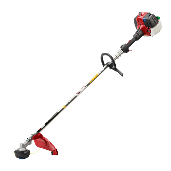
- Page 1 Brushcutter BCZ 350S BCZ 350S Workshop Manual 115 47 91-26 115 47 91-26...
-
Page 2: Table Of Contents
Starter Workshop Manual Brushcutter Model BCZ 350S Contents General recommendations _____________________ 2 1. Starter ___________________________________ 3 2. Electrical system __________________________ 7 3. Fuel system _____________________________ 13 4. Centrifugal clutch ________________________ 29 5. Angle gear ______________________________ 35 6. Cylinder and piston _______________________ 39 7. -
Page 3: General Recommendations
Starter General recommendations The workshop used to carry out repairs must be equipped Fire risk with safety devices in accordance with local directives. Handle fuel with respect as it is extremely infl ammable. No one may carry out repairs without fi rst having read and understood the contents of this Workshop Manual. -
Page 4: Starter
Starter Starter Contents Dismantling ___________________________________ 4 Assembly _____________________________________ 5 Replacing the drive dogs _________________________ 6... - Page 5 Starter WARNING! Protective glasses should be worn when working on the starter to avoid injury to the eyes if, for some reason, the return spring should fl y out. 502 50 18-01 Dismantling Demontering Remove the starter from the engine. Remove the 4 screws and carefully swing down the protective plate so far that the starter can be lifted out.
- Page 6 Starter Assembly Assembly Clean the component parts and assem- Clean component parts before ble in the reverse order as set out for assembling. dismantling. Replace the return spring/starter pulley and starter cord, if necessary. NOTE! The return spring and starter pulley are supplied pre-assembled and are fi...
- Page 7 Starter Fit the starter on the engine body. 1. Check that the rubber bushings (A) are in position in the starter housing. 2. Swing the starter in against the engine body. 3. Press the starter in against the engine body. 4.
-
Page 8: Electrical System
Electrical system Electrical system Contents Checking the ignition spark ___________________ 8 Dismantling _______________________________10 Assembly _________________________________12... - Page 9 Electrical system The engine is equipped with an electronic ignition system completely without moving parts. Consequently, a faulty component cannot be repaired, but must be replaced by a new component. The spark in an electronic ignition system has a very short burn time and can therefore be interpreted as weak and can be diffi...
- Page 10 Electrical system When there is still no ignition spark, When there is still no ignition spark, dismantle the short-circuit cable from the dismantle the short-circuit cable from the stop switch. stop switch. Still no spark? Dismantle the switch. (See chapter 3 "Throttle").
- Page 11 Electrical system Still no spark? Still no spark? Check other cables and connections. Check other cables and connections for poor contacts (dirt, corrosion, cable breakage and damaged insulation). Make sure that the cables are correctly drawn and lie in the cable grooves. Do not forget to check the cables in the throttle too.
- Page 12 Electrical system Dismantle the protective cover, remove Dismantle the protective cover under the screws (E) and swing the engine the engine body (3 screws). body to the side. Lift out the ignition lead and short-circuit cables from their guides. Remove the 3 screws (E) and swing the engine body to one side so the clutch becomes accessible.
- Page 13 Electrical system Remove the fl ywheel. Dismantle the fl ywheel from the crank- case using the puller no. 502 51 49-01. Gently knock the puller screw with a hammer, if the fl ywheel sits tightly on the crankshaft. 502 51 49-01 Assembly Check that the cast key in the fl...
-
Page 14: Fuel System
Fuel system Fuel system Contents Air fi lter ___________________________________ 14 Tank venting _______________________________ 15 Fuel fi lter __________________________________ 15 Fuel pump _________________________________ 16 Carburettor ________________________________ 16 Throttle ___________________________________ 24 Carburettor settings __________________________ 26... -
Page 15: Air Fi Lter
Fuel system In addition to the fuel tank and carburettor, the fuel system consists of the air fi lter, fuel fi lter and tank venting. All these components interact so that the engine receives the optimal mixture of fuel and air to make it as effi... -
Page 16: Tank Venting
Fuel system Tank venting Tank venting Tank venting takes place through the Check that the tank venting valve works fuel cap and needs to be functional for correctly. the engine to work. Replace the fuel cap if the valve is •... -
Page 17: Fuel Pump
Fuel system Fuel pump Fuel pump The fuel pump facilitates cold starts. The fuel pump has the task of facilitating the start of the engine when cold. The The pump cannot be repaired and must pump fi lls the carburettor with fuel be replaced if it stops working. - Page 18 Fuel system The blending unit The blending unit Fuel and air are mixed here. In this section of the carburettor fuel and air are mixed in the proper proportions. The choke and throttle valves are pla- ced here. In the middle of the venturi (narrowest part of the throughput) the main jet (D) is found.
- Page 19 Fuel system Pressure test the metering unit. Connect pressure tester 531 03 06-23 to the fuel hose nipple. Lower the carburettor in a vessel with petrol in order to discover any leaks more easily. Test the pressure at 50 kPa. No leakage is permitted.
- Page 20 Fuel system Remove the pump diaphragm. Remove the bolt holding the cover over the pump diaphragm. Check the diaphragm for damage. Lift off the cover (A), the gasket (B) and Remove the fuel screen and clean it or the diaphragm (C). attach a new one.
- Page 21 Fuel system Remove the valves and dampers. If these components are worn, idling is disrupted. Always replace the valves and dampers at the same time. Assembling the carburettor Assembling the carburettor Blow the carburettor housing clean. • Blow all channels in the carburettor compartment clean Fit a new plug.
- Page 22 Fuel system • Mount the valves and dampers. Replace the fuel screen if it is damaged or cannot be cleaned. Place the pump diaphragm closest to the carburettor housing. Then the gasket and cover and the other components in reverse order of removal.
- Page 23 Fuel system Fit the jet needles and adjust their set- ting. H = 2 revolution open L = 1,5 revolution open NOTE! The H-needle is a little shorter than the L-needle. Press the stop plugs (A) in position using tool 540 06 82-01. Check that the O-ring is correctly seated and that the slot in the plug aligns with the ball (B) in the carburettor housing.
- Page 24 Fuel system The holder for the air fi lter contains a device that opens two air ducts in the cylinder during acceleration. A rotary valve connected to the throttle valve lever opens the air supply in proportion to the acceleration. The device has the task of preventing uncombusted fuel/air mixture from going directly out into the exhaust channel.
-
Page 25: Throttle
Fuel system Assembly 1. Fit the rubber connection (A) on the cylinder. Lubricate with oil so it slides into the holes. 2. Fit the heat shield (B). Lubricate the connection sleeves with oil so they slide into the rubber connection. Check that the bush (C) and brass sleeves (D) are seated correctly. - Page 26 Fuel system Pay attention when the halves are sepa- rated so that both rubber elements (1), one on each side, are not lost. Remove the short-circuit cable from the switch (2). Lift up the throttle cable (3) from the channel and unhook it from the throttle (4).
-
Page 27: Carburettor Settings
Fuel system Carburettor settings WARNING! When testing the engine in connection with carburettor adjustment, the clutch and clutch cover must be mounted together with the shaft and angle gear under all circumstances Otherwise there is a risk of the clutch becoming loose resulting in serious personal injury. - Page 28 Fuel system NOTE! A tachometer should always be used to fi nd the optimal setting. The recommended max. speed must not be exceeded. 501 60 02-03 502 71 14-01 Idling speed T-screw Let the engine idle for about 30 seconds or until the speed has High speed needle H stabilised.
- Page 29 Fuel system Setting the L needle Setting the H needle 1. Fit the trimmer head P35 and use 2.7 mm plain cord. The 1. Fit the trimmer head P35 and use 2.7 mm plain cord. The cord length should be as standard, i.e. reach the knife on the cord length should be as standard, i.e.
-
Page 30: Centrifugal Clutch
Centrifugal clutch Centrifugal clutch Contents Centrifugal clutch – Dismantling ________________ 30 Centrifugal clutch – Assembly __________________ 31 Clutch drum and drive axle – Dismantling _________ 31 Clutch drum and drive axle – Assembly __________ 33... - Page 31 Centrifugal clutch The centrifugal clutch has the task of transferring the power from the engine to the cutting equipment’s drive axle. As the name implies, it works according to a centrifugal principle. This means the clutch’s friction shoes are thrown outwards towards the clutch drum at a certain engine speed.
- Page 32 Centrifugal clutch Assembly Connect the clutch shoes together with the spring. NOTE! Both clutch shoes should be replaced even if only one of them is showing signs of heavy wear. This is to avoid engine vibration caused by imbalance in the clutch. Bolt the clutch on the fl...
- Page 33 Centrifugal clutch Dismantle the circlip and press out the Dismantle the circlip using circlip pliers. clutch drum. Press out the clutch drum using a suita- ble punch and hammer. Dismantle the circlip and heat the clutch Dismantle the circlip using circlip pliers. cover so the bearing can be dismantled.
- Page 34 Centrifugal clutch On models with a two-piece shaft, the On models with a two-piece shaft, the guide becomes accessible once the guide becomes accessible once the shaft has been split (see chapter 3). shaft has been split (see chapter 3). Dismantle the sleeve (A) and pull out the guide (B) by pulling the drive axle.
- Page 35 Centrifugal clutch...
-
Page 36: Angle Gear
Angle gear Angle gear Contents Dismantling ________________________________ 36 Assembly __________________________________ 37 Drive axle __________________________________ 37... - Page 37 Angle gear The angle gear has two purposes: The fi rst is to gear down the engine’s high speed to better suit the lower speed a saw blade or trimmer requires to work effi ciently. Secondly, the angle gear contributes towards the operator’s working stance so that it is comfortable and at the same time effi...
- Page 38 Angle gear Dismantle the bearings from the output Dismantle the bearings from the output and input axles. and input axles with the help of a small bearing puller. TIP! Hold the bearing puller in a vice so that it gains a better grip around the bearing. Assembly Clean all component parts and replace if damaged or worn.
- Page 39 Angle gear The drive axle control becomes acces- The drive axle control becomes acces- sible once the shaft has been split (see sible once the shaft has been split (see chapter 3). chapter 3). Dismantle the sleeve (A) and pull out the guide (B) by pulling the drive axle.
-
Page 40: Cylinder And Piston
Cylinder and piston Cylinder and piston Contents Dismantling ________________________________ 40 Cleaning, inspection _________________________ 41 Analysis and actions _________________________ 41 Service tips ________________________________ 46 Wear tolerances ____________________________ 46 Assembly __________________________________ 47... -
Page 41: Dismantling
Cylinder and piston The cylinder and the piston are two of the components exposed to most strain in the engine. They must withstand, for example, high speeds, large temperature swings and high pressure. Moreover, they must be resistant to wear. Despite these tough working conditions, major piston and cylinder failure is relatively uncommon. -
Page 42: Cleaning, Inspection
Cylinder and piston Cleaning, inspection After dismantling, clean the individual components: 1. Scrape carbon deposits from the top of the piston. 2. Scrape carbon deposits from the cylinder’s combustion chamber. 3. Scrape carbon deposits from the cylinder’s exhaust port. NOTE! Scrape carefully with not too sharp a tool so as not to damage the soft aluminium parts. - Page 43 Blocked spark arrestor mesh in mesh. the muffl er. For the best results we recommend RedMax two-stroke oil or ready-mixed fuel that is specially developed for air-cooled two-stroke engines. Mixing ratio: 1:50 (2%). If RedMax two-stroke oil is not available another good quality two-stroke oil can be used.
- Page 44 Cylinder and piston Piston damage caused by a too high engine speed. Typical damage associated with a too high engine speed includes broken piston rings, broken circlip on the gudgeon pin, faulty bearings or that the guide pin for the piston ring has become loose.
- Page 45 Cylinder and piston Foreign objects Everything other than clean air and pure fuel that enters the engine’s inlet port cau- ses some type of abnormal wear or damage to the cylinder and piston. This type of increased wear shows on the piston’s inlet side starting at the lower edge of the piston skirt.
- Page 46 Cylinder and piston Larger, softer particles that penetrate into the engine cause damage to the piston skirt under the piston ring as the illustration shows. Cause: Action: • Air fi lter incorrectly fi tted. Fit the air fi lter correctly. •...
-
Page 47: Service Tips
Cylinder and piston Service tips Defect: Action: Broken cooling fi ns, damaged threads or sheared bolts by In severe cases – replace the cylinder. the exhaust port. Repair the threads using Heli-Coil. Seizure marks in the cylinder bore (especially by the ex- Polish the damaged area using a fi... -
Page 48: Assembly
Cylinder and piston Assembly Assembly Clean the crankcase. Clean the crankcase. Fit the piston on the connecting rod Assemble the piston on the connecting so that the arrow on the piston points rod. towards the exhaust port. Lubricate the gudgeon pin’s needle bearing with a few drops of engine oil. - Page 49 Cylinder and piston...
-
Page 50: Crankshaft And Crankcase
Crankshaft and crankcase Crankshaft and crankcase Contents Dismantling ________________________________ 50 Inspecting the crankshaft ______________________ 52 Assembly _________________________________ 52... - Page 51 Crankshaft and crankcase The task of the crankshaft is to transform the reciprocating motion of the piston to rotation. This requires a stable design withstanding immense pressure and rotational and bending strain, as well as high rotational speed. In addition the connecting rod is exposed to large acceleration and retardation forces as it moves bet- ween the top and bottom dead centres.
- Page 52 Crankshaft and crankcase Lift off the plastic piece that separates Lift off the plastic piece that separates the wide fl ush channel in the crankcase. the wide fl ush channel in the crankcase. Dismantle the ball-bearings from the Dismantle the ball-bearings from the crankcase halves.
- Page 53 Crankshaft and crankcase Inspecting the Inspecting the crankshaft crankshaft Inspect the large end of the connecting The crankshaft cannot be reconditioned rod. but must be replaced if it is worn or damaged. Inspect the large end of the connecting rod. If seizure marks, discolouration on the sides or damaged needle holders are found the crankshaft must be repla- ced.
- Page 54 Crankshaft and crankcase Fit the sealing rings in the crankcase Fit the sealing rings in the crankcase halves. halves with the help of a suitable punch. Turn the sealing rings so the metal collar faces outwards. Fit the crankshaft, guide sleeves and Fit the crankshaft in the clutch side’s guide rail in the clutch side’s crankcase crankcase half.
- Page 55 Crankshaft and crankcase Assemble the cylinder. Assemble the cylinder. Position the cylinder base gasket. Lubricate the piston and piston rings with a few drops of oil. Use the piston ring compressor and carefully slide the cylinder into position. Tighten the four screws, crosswise. Assemble the remaining parts in the reverse order as set out for dismantling.
-
Page 56: Tools
List of tools Tools Contents Starter __________________________________ 56 Electrical system __________________________ 56 Fuel system ______________________________ 56 Centrifugal clutch __________________________ 56 Angle gear _______________________________ 57 Cylinder and piston ________________________ 57 Crankshaft and crankcase ___________________ 57 Workshop equipment _______________________ 57... - Page 57 List of tools 531 03 06-23 531 00 48-63 502 50 18-01 502 51 91-01 502 50 18-01 502 51 49-01 502 71 13-01 531 00 60-76 502 71 14-01 503 80 17-01 502 50 83-01 502 51 34-02 502 50 64-01 502 50 06-01 540 06 82-01 502 50 18-01...
- Page 58 List of tools 502 51 03-01 503 97 64-01 502 50 18-01 502 50 18-01 503 80 17-01 502 52 42-01 502 50 70-01 531 03 06-23 502 50 70-01 502 71 14-01...
- Page 59 List of tools...
-
Page 60: Technical Data
Technical data Technical data Contents Engine __________________________________ 60 Ignition system ____________________________ 60 Carburettor ______________________________ 60 Clutch __________________________________ 60 Driving __________________________________ 60 Dimensions ______________________________ 60 Vibrations ________________________________ 60... - Page 61 Technical data Engine BCZ 350S Displacement, cm 34.6 Cylinder bore, mm 38.0 Stroke, mm 30.5 Compression ratio 10.5 Max output, kW / speed, r/min 1.6 / 8400 Ignition system Walbro digital, max speed, r/min 11800 Pre-ignition at max output, degrees...
Need help?
Do you have a question about the BCZ 350S and is the answer not in the manual?
Questions and answers