Table of Contents
Advertisement
Quick Links
SERVICE & OPERATING MANUAL
Original Instructions
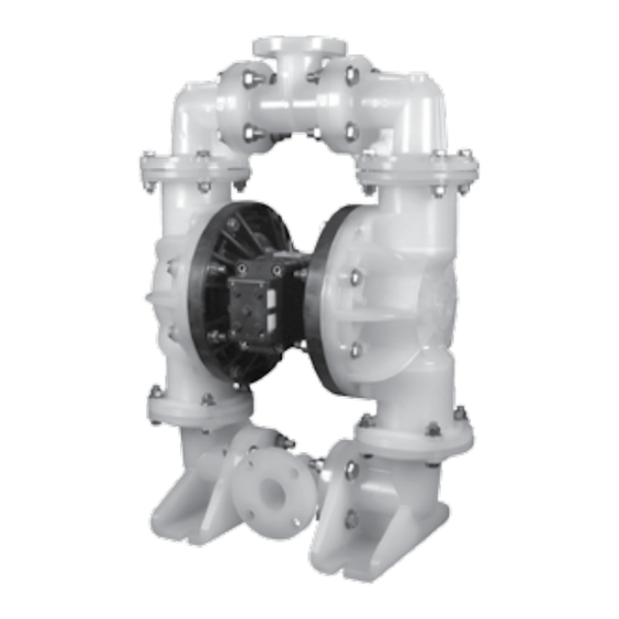
Model M20 Non-Metallic Design Level 3
Table of Contents
Engineering Data and Temperature Limitations ....................................................................... 1
Explanation of Pump Nomenclature ......................................................................................... 2
Performance Curve, Model M20 Non-Metallic Design Level 3 ................................................. 3
Dimensions: M20 Non-Metallic ................................................................................................. 4
Dimensions: M20 Non-Metallic with Spill Containment ............................................................. 5
Principle of Pump Operation..................................................................................................... 6
Installation and Start-up............................................................................................................ 6
Air Supply ................................................................................................................................. 6
Air Valve Lubrication ................................................................................................................. 6
Air Line Moisture....................................................................................................................... 6
Air Inlet and Priming ................................................................................................................. 6
Between Uses .......................................................................................................................... 6
Installation Guide ...................................................................................................................... 7
Recycling .................................................................................................................................. 8
Important Safety Information .................................................................................................... 8
Material Codes ......................................................................................................................... 9
Troubleshooting ...................................................................................................................... 10
Warranty ................................................................................................................................. 10
Composite Repair Parts Drawing ........................................................................................... 12
Repair Parts Servicing Kits ..................................................................................................... 12
Composite Repair Parts List ................................................................................................... 13
Spill Containment Option ....................................................................................................... 14
Spill Containment Repair Parts List ........................................................................................ 14
Spill Containment Concept ..................................................................................................... 14
Spill Containment Option Diaphragm Servicing .................................................................... 15
Filling Chambers with Liquid................................................................................................... 15
Air Distribution Valve Assembly Drawing ................................................................................ 16
Main Air Valve Assembly Parts List ........................................................................................ 16
Air Distribution Valve Servicing ............................................................................................... 17
Air Distribution Valve with Stroke Indicator Options ............................................................... 18
Air Distribution Valve with Stroke Indicator Parts List ............................................................ 18
Air Distribution Valve with Stroke Indicator Servicing ............................................................. 19
m20nmdl3sm-rev0814
Warren Rupp, Inc. • A Unit of IDEX Corporation • 800 N. Main St., Mansfield, Ohio 44902 USA
Telephone (419) 524-8388 • Fax (419) 522-7867 • www.warrenrupp.com
Solenoid Shifted Air Valve Drawing ........................................................................................ 20
Solenoid Shifted Air Valve Parts List ...................................................................................... 20
Solenoid Shifted Air Distribution Valve option ......................................................................... 21
Diaphragm Service Drawing, Non-Overlay............................................................................. 22
Diaphragm Service Drawing, with Overlay ............................................................................. 22
Diaphragm Servicing .............................................................................................................. 23
Overlay Diaphragm Service ................................................................................................... 23
Pilot Valve Assembly Drawing ................................................................................................ 24
Pilot Valve Assembly Parts List .............................................................................................. 24
Pilot Valve Servicing ............................................................................................................... 24
Pumping Hazardous Liquids................................................................................................... 25
Converting the Pump for Piping the Exhaust Air .................................................................... 25
Exhaust Conversion Drawing ................................................................................................. 25
Converted Exhaust Illustration................................................................................................ 25
Modular Check Valve Servicing .............................................................................................. 26
Modular Check Valve Drawing ............................................................................................... 26
Dual Port Option Drawing ....................................................................................................... 27
Dual Porting Options .............................................................................................................. 27
Dual Porting of Both Suction and Discharge Ends of the Pump............................................. 27
Single Porting of the Suction and Dual Porting of the Pump Discharge ................................. 27
Dual Porting of the Suction and Single Porting of the Pump Discharge ................................. 27
Leak Detection Options Drawing ............................................................................................ 28
Electronic Leak Detector Installation ...................................................................................... 28
Mechanical Leak Detector Installation .................................................................................... 28
Pulse Output Kit Drawing ....................................................................................................... 29
Pulse Output Kit Option .......................................................................................................... 29
Optional Muffler Configurations .............................................................................................. 30
Grounding the Pump .............................................................................................................. 31
CE Declaration of Conformity Machinery ............................................................................... 32
CE Declaration of Conformity ATEX ....................................................................................... 33
Explanation of ATEX Certifications ......................................................................................... 34
See pages 2, 33 and 34
See page 2
for ATEX ratings.
for ATEX ratings.
©Copyright 2014 Warren Rupp, Inc. All rights reserved.
Advertisement
Table of Contents

Related Manuals for Idex Warren Rupp MARATHON M20


Summary of Contents for Idex Warren Rupp MARATHON M20
-
Page 1: Table Of Contents
Explanation of ATEX Certifications ..................34 Air Distribution Valve with Stroke Indicator Servicing ............. 19 Warren Rupp, Inc. • A Unit of IDEX Corporation • 800 N. Main St., Mansfield, Ohio 44902 USA Telephone (419) 524-8388 • Fax (419) 522-7867 • www.warrenrupp.com m20nmdl3sm-rev0814 ©Copyright 2014 Warren Rupp, Inc. -
Page 3: Engineering Data And Temperature Limitations
Non-Metallic See pages 2, 33 and 34 See page 2 Quality System for ATEX ratings. for ATEX ratings. Ball Valve ISO9001 Certified Environmental Design Level 3 Management System ISO14001 Certified Air Operated Double Diaphragm Pump ENGINEERING, PERFORMANCE & CONSTRUCTION DATA INTAKE/DISCHARGE PIPE SIZE CAPACITY AIR VALVE... -
Page 4: Explanation Of Pump Nomenclature
Explanation of Pump Nomenclature M20 Non-Metallic · Design Level 3 · Ball Valve Check Diaphragm/ Check Non-Wetted Shipping Model Pump Pump Valve Design Wetted Check Valve Valve Material Porting Pump Pump Weight Brand Size Type Level Material Materials Seat Options Options Style Options Options... -
Page 5: Performance Curve, Model M20 Non-Metallic Design Level 3
Performance Curve, Model M20 Non-Metallic Design Level 3 MODEL S20 Non-Metallic Performance Curve Performance based on the following: elastomer fitted pump, flooded suction, water at ambient conditions. The use of other materials and varying hydraulic conditions may result in deviations in excess of 5%. (34) Displacement Per Stroke: .46 Gallons... -
Page 6: Dimensions: M20 Non-Metallic
Dimensions: M20 Non-Metallic Dimensions in Inches [ ] in Millimeters Dimensional tolerance: +/- 1/8" [ ] +/- 3mm Note: Porting Flanges are also available with PN10 50mm DIN bolting configuration m20nmdl3sm-rev0814 Model M20 Non-Metallic Page 4... -
Page 7: Dimensions: M20 Non-Metallic With Spill Containment
Dimensions: M20 Non-Metallic with Spill Containment Dimensions in Inches [ ] in Millimeters Dimensional tolerance: +/- 1/8" [ ] +/- 3mm Note: Porting Flanges are also available with PN10 50mm DIN bolting configuration m20nmdl3sm-rev0814 Model M20 Non-Metallic Page 5... -
Page 8: Principle Of Pump Operation
PRINCIPLE OF PUMP OPERATION is reversed. The air distribution valve piping. The weight of the air supply line, problems. This ball type check valve pump spool is moved by a internal pilot valve regulators and filters must be supported AIR INLET AND PRIMING is powered by compressed air and is which alternately pressurizes one end by some means other than the air... -
Page 9: Installation Guide
TYPICAL INSTALLATION GUIDE For Non-Metallic Pumps Available from MARATHON Air Inlet 100 psi Line CAUTION The air exhaust should be piped to an area for safe disposition of the product being pumped, in the event of a diaphragm failure. m20nmdl3sm-rev0814 Model M20 Non-Metallic Page 7... -
Page 10: Recycling
RECYCLING IMPORTANT SAFETY WARNING INFORMATION Many components of MARATHON AODD ® Take action to prevent static pumps are made of recyclable materials (see sparking. Fire or explosion chart on page 9 for material specifications). can result, especially when We encourage pump users to recycle worn handling flammable liquids. -
Page 11: Material Codes
Material Codes The Last 3 Digits of Part Number Assembly, sub-assembly; Copper Alloy High Density Polypropylene PTFE and some purchased items Carbon Steel, Black Epoxy Coated Conductive Nitrile PTFE Cast Iron Carbon Steel, Black PTFE Coated Cellulose Fibre Envelon Powered Metal Aluminum, Black Epoxy Coated Cork and Neoprene Conductive PTFE... -
Page 12: Troubleshooting
TROUBLESHOOTING Corrective Action: Meet or exceed Corrective Action: Disassemble C o r r e c t i v e A c t i o n : C h e c k f o r Possible Symptoms: pump connection recommendations pump chambers. Inspect for diaphragm obstruction or closed discharge line •... - Page 13 m20nmdl3sm-rev0814 Model M20 Non-Metallic Page 11...
-
Page 14: Composite Repair Parts Drawing
Composite Repair Drawing Torque: 476-253-000 AIR END KIT 400 in. lbs. Seals, O-Rings, Gaskets, Retaining Rings, Air Valve Sleeve & Spool Set and Pilot Valve Assembly 476-254-000 AIR END KIT (for Stroke Indicator Option) Torque: Seals, O-Rings, Gaskets, 480 in. lbs. Retaining Rings, Air Valve Torque: Sleeve &... -
Page 15: Composite Repair Parts List
Composite Repair Parts List ITEM PART NUMBER DESCRIPTION 312-116-520 Elbow, Suction ITEM PART NUMBER DESCRIPTION 312-116-552 Elbow, Suction 312-116-557 Elbow, Suction 031-140-000 Air Valve Assembly 360-093-360 Gasket, Main Air Valve 031-140-001 Air Valve Assembly 360-103-360 Gasket, Pilot Valve 031-140-002 Air Valve Assembly w/ PTFE coated Hardware 360-104-360 Gasket, Air Inlet Cap 031-141-000... -
Page 16: Spill Containment Option
Spill Containment Option M20 Spill Containment Repair Parts List ITEM PART NUMBER DESCRIPTION 031-146-000 Air Valve Assembly (replaces 031-140-000) 031-147-000 Air Valve Assembly (replaces 031-141-000) 170-073-115 Capscrew, Hex HD 1/2-13 x 4.50 (replaces 170-068-115) 170-073-308 Capscrew, Hex HD 1/2-13 x 4.50 (replaces170-068-115) 170-102-115 Capscrew, Hex HD 1/2-13 x 6.00... -
Page 17: Spill Containment Option Diaphragm Servicing
SPILL CONTAINMENT CONCEPT ml (65.9 fl. oz.). It is important that the 10. Repeat steps 5 through 9 to fill outer chamber (items 16 from the pump The spill containment option exact amount of fluid is used. Too little opposite spill containment chamber. assembly drawing). -
Page 18: Air Distribution Valve Assembly Drawing
Air Distribution Valve Assembly Drawing M20 Design Level 3 AIR VALVE ASSEMBLY PARTS LIST Item Part Number Description 031-140-000 Air Valve Assembly 031-139-000 Sleeve and Spool Set 095-094-551 Body, Air Valve 132-029-552 Bumper 165-096-551 Cap, Muffler 165-115-558 Cap, End 530-028-550 Muffler 560-020-360 O-Ring... -
Page 19: Air Distribution Valve Servicing
AIR DISTRIBUTION VALVE Inspect the inner diameter of the IMPORTANT SERVICING sleeve (part of item 1-A) for dirt, To service the air valve first shut off scratches, or other contaminates. Read these instructions the compressed air, bleed the pressure Remove the sleeve if needed and c o m p l e t e l y, b e f o r e from the pump, and disconnect the air replace both the sleeve and spool with... -
Page 20: Air Distribution Valve With Stroke Indicator Options
Air Valve Assembly Drawing with Stroke Indicator Option M20 Design Level 3 PILOT VALVE ASSEMBLY PARTS LIST Item Part Number Description 031-146-000 Air Valve Assembly Note: Stroke Indicator is standard on Spill Containment models 031-143-000 Sleeve and Spool Set w/Pins 1 095-094-559 Body, Air Valve 132-029-552... -
Page 21: Air Distribution Valve With Stroke Indicator Servicing
AIR DISTRIBUTION VALVE WITH Inspect the inner diameter of the IMPORTANT STROKE INDICATOR OPTION sleeve (part of item 1-A) for dirt, SERVICING scratches, or other contaminates. Read these instructions To service the air valve first shut off Remove the sleeve if needed and c o m p l e t e l y, b e f o r e the compressed air, bleed the pressure replace both the sleeve and spool with... -
Page 22: Solenoid Shifted Air Valve Drawing
Solenoid Shifted Air Valve Drawing SOLENOID SHIFTED AIR VALVE PARTS LIST (Includes All Items Used on Composite Repair Parts List Except as Shown) Item Part Number Description 893-097-000 Solenoid Valve, NEMA4 219-001-000 Solenoid Coil, 24VDC 219-004-000 Solenoid Coil, 24VAC/12VDC 219-002-000 Solenoid Coil, 120VAC 219-003-000 Solenoid Coil, 240VAC... -
Page 23: Solenoid Shifted Air Distribution Valve Option
SOLENOID SHIFTED AIR Wiring Solenoid Connector DISTRIBUTION VALVE OPTION Diagram MARATHON’s solenoid shifted, 3rd Terminal for air distribution valve option utilizes ground. electrical signals to precisely control Before wiring, remove #2 Terminal Neutral #1 Terminal your MARATHON’s speed. The terminal block from (Negative) Power solenoid coil is connected to a customer... -
Page 24: Diaphragm Service Drawing, Non-Overlay
Diaphragm Service Drawing with Overlay Torque: 480 in/lbs Diaphragm Service Drawing, Non-Overlay Torque: 480 in/lbs Field conversion kit 475-256-000 available for conversion from PTFE Overlay to One-Piece bonded Diaphragm Part Description 286-114-000 One-Piece Diaphragm 612-227-150 Plate, Inner Diaphragm m20nmdl3sm-rev0814 Model M20 Non-Metallic Page 22... -
Page 25: Diaphragm Servicing
DIAPHRAGM SERVICING diaphragms if necessary. the inner chamber. IMPORTANT To service the diaphragms first Step #4: Installing the diaphragms. Fasten the remaining outer chamber shut off the suction, then shut off the Push the threaded stud of the outer (item 16) to the pump, using the Read these instructions discharge lines to the pump. -
Page 26: Pilot Valve Assembly Drawing
Pilot Valve Servicing, Assembly Drawing & Parts List PILOT VALVE ASSEMBLY PARTS LIST ITEM PART NUMBER DESCRIPTION 095-110-558 Pilot Valve Assembly 095-095-558 Valve Body 755-052-000 Sleeve (With O-rings) 560-033-360 O-ring (Sleeve) 775-055-000 Spool (With O-rings) 560-023-360 O-ring (Spool) 675-037-080 Retaining Ring PILOT VALVE SERVICING STEP #2: Disassembly of the STEP #3: Re-assembly of the... -
Page 27: Pumping Hazardous Liquids
PUMPING HAZARDOUS LIQUIDS NOTE: The manufacturer recommends CONVERTED EXHAUST ILLUSTRATION When a diaphragm fails, the pumped installing a flexible hose or connection PUMP INSTALLATION AREA liquid or fumes enter the air end of the between the pump and any rigid SAFE AIR EXHAUST pump. -
Page 28: Modular Check Valve Servicing
Modular Check Valve Drawing MODULAR CHECK VALVE Remove the remaining check valve SERVICING seal (item 37). Inspect the seal for Before servicing the check valves, cuts or pinched areas. Replace seal first shut off the suction line and then as needed. the discharge line to the pump. -
Page 29: Dual Port Option Drawing
Dual Port Option Drawing DUAL PORTING OPTIONS SINGLE PORTING OF THE SUCTION AND DUAL PORTING OF THE PUMP Several dual porting options are possible. The pump can be converted DISCHARGE to a dual port arrangement on both To convert the pump from the the suction and the discharge ends. -
Page 30: Leak Detection Options Drawing
Leak Detection Options Drawing LEAK DETECTION OPTION (ELECTRONIC) Follow instructions found elsewhere in this manual, “Filling the Spill Prevention Chambers” when installing leak detectors. Electronic Leak Detector Installation Kit 032-037-000 100VAC 50Hz or 110-120VAC 50/60Hz or 220-240VAC 50/60Hz Kit 032-045-000 12-32VDC To install electronic leak detectors, remove the bottom ¼"... -
Page 31: Pulse Output Kit Drawing
Pulse Output Kit Drawing PULSE OUTPUT KIT OPTION This pump can be fitted with a Pulse Output Kit. This converts the mechanical strokes of the pump to an electrical signal which interfaces with the Stroke Counter/ Batch Controller or user control devices such as a PLC. The Pulse Output Kits mount directly onto the Muffler Cap on the Air Distribution Valve Assembly or onto the air valve and senses each stroke of the main spool. -
Page 32: Optional Muffler Configurations
Optional Muffler Configurations, Drawing OPTION 0 530-028-550 Encapsulated Muffler uses (1) Cap and (4) 710-015-115 Self Tapping Screw to hold it in place. OPTION 1 530-027-000 Sound Dampening Muffler screws directly into the Air Valve body. This muffler is equipped with a porous plastic element. -
Page 33: Grounding The Pump
Grounding The Pump To be fully groundable, the pumps must be ATEX Compliant. Refer to pump data sheet for ordering. One eyelet end is fastened to the pump hardware. This optional 8 foot long (244 centimeters) Ground Strap The other end is installed to a true earth ground. (920-025-000) is available for easy ground connection. -
Page 34: Ce Declaration Of Conformity Machinery
Declaration of Conformity Manufacturer: Warren Rupp, Inc. , 800 N. Main Street, P.O. Box 1568, ® Mansfield, Ohio, 44901-1568 USA certifies that Air-Operated Double Diaphragm Pump Series: M Non-Metallic, M Metallic, and Surge Suppressors comply with the European Community Directive 2006/42/EC on Machinery, according to Annex VIII. -
Page 35: Ce Declaration Of Conformity Atex
EC Declaration of Conformity In accordance with ATEX Directive 94/9/EC, Equipment intended for use in potentially explosive environments. Manufacturer: Warren Rupp, Inc. , A Unit of IDEX Corportion ® 800 North Main Street, P.O. Box 1568, Mansfield, OH 44901-1568 USA EN 60079-25: 2011... -
Page 36: Explanation Of Atex Certifications
EC Declaration of Conformity ATEX Summary of Markings Non-Conductive Type Marking Listed In Fluids Pump types, M05, M1F, M15, II 2 G Ex ia c IIC T5 KEMA 09ATEX0071 X KEMA 09ATEX0071 X M20 and M30 provided with the II 3/2 G Ex ia c IIC T5 CE 0344 KEMA 09ATEX0071 X pulse output option...
Need help?
Do you have a question about the Warren Rupp MARATHON M20 and is the answer not in the manual?
Questions and answers