Table of Contents
Advertisement
Advertisement
Table of Contents

Related Manuals for Idex HALE SmartCAFS


Summary of Contents for Idex HALE SmartCAFS
- Page 1 SmartCAFS Installation and Operation Manual HALE PRODUCTS, INC. A Unit of IDEX Corporation 607 NW 27 Ocala, FL 34475 United States 800-533-3569 800-520-3473 FSG-MNL-00157 www.haleproducts.com REV D, July 2020 Halecustomerservice@idexcorp.com...
-
Page 2: Revision Record
Page 2 of 116 REVISION RECORD Date Page Description 28DEC2015 New Issue 24JAN2017 Drawings Revised Drawing Update 21, 22 Add pictures of gear pump w/ new motor driver 21AUG2018 Changed separator element replacement kit QTY from 1 to 2 13JUL2020 Added Dual Foam data Updated manifolds Updated dimensional diagrams... -
Page 3: Table Of Contents
Page 3 of 116 T.O.C. Table of Contents REVISION RECORD ........................2 T.O.C.............................. 3 INTRODUCTION ..........................7 ENVIRONMENTAL PROTECTION ....................7 SAFETY - RELEVANT DATA ......................8 ............................. 8 AINTENANCE ............................8 RAINING ..............................9 OISE ............................. 9 AUGES ......................... - Page 4 Page 4 of 116 3.3, 5.0, 6.5 S – R ................ 21 OAM UNIT YSTEM EMOTE OUNTED ........................22 OAM UNIT IMENSIONS INSTALLATION AND INITIAL SET-UP ..................24 ..........................24 IFTING OINTS ..........................24 TRAP IFT POINTS DRIVE LINE ..........................25 ..........................
- Page 5 Page 5 of 116 ............................53 OAM POWER BUTTON ......................53 OAM INCREASE AND DECREASE BUTTONS ........................53 WATER PRESSURE DUPLEX GAUGE ..............................53 OME BUTTON ..............................53 URRENT PRESET ..............................54 IR DISPLAY CAFS ..........................54 WATER FLOW RATIO CAFS ARC ..........................
- Page 6 Page 6 of 116 ON-SCREEN WARNINGS AND INFORMATION ................ 75 MAINTENANCE MINDER ......................76 ROUTINE MAINTENANCE ......................78 ....................79 OMPRESSOR OISTURE RAIN ........................... 80 IL AND ILTER ....................... 81 OOLING ATER TRAINER ........................81 LEANER LEMENT COMPRESSOR BELT MAINTENANCE ..................82 ........................
-
Page 7: Introduction
Page 7 of 116 INTRODUCTION This manual contains information relevant to HALE Series Pumps, when partnered with Compressed Air Foam Systems (CAFS) Foam unit Models 3.3, 5.0 and 6.5 and the UV SmartCAFS control system. Distinction between the models regarding Installation, Maintenance and Operation is clearly noted with text and illustrations. -
Page 8: Safety - Relevant Data
Page 8 of 116 SAFETY - RELEVANT DATA Thank you for purchasing a HALE Pump. HALE Pumps are designed to give safe and reliable service. BEFORE use however, it is essential that the Operating and Installation Instructions are carefully read and understood. MAINTENANCE It is the responsibility of the user to ensure that the equipment is maintained in a safe operational condition. -
Page 9: Noise
Page 9 of 116 WARNING ONCE A NOZZLE HAS BEEN SELECTED IT IS IMPERATIVE TO PROVIDE AMPLE TRAINING IN THE USE OF THE NOZZLE. OPEN CAFS NOZZLES SLOWLY AND MAKE SURE THE NOZZLE IS SECURED AGAINST REACTION FORCE. • Do not remove the cap from the FS series water strainer from the CAFS system while the unit is running. -
Page 10: General Data
Page 10 of 116 GENERAL DATA COMPRESSOR Model Enduro 12 Maximum Operating Speed 6500 rev/min Nominal speed of operation 5000 rev/min Nominal power consumption 75HP [56.0kW] Direction of rotation Counter-clockwise (viewed on pulley) Volume output 210 SCFM [5946 l/min] @ 125 PSI [8.6 Bar] Operational pressure range 75-150 PSI [5.1-10.3 Bar] PUMP... -
Page 11: Lubricants
Page 11 of 116 LUBRICANTS COMPRESSOR SYSTEM Recommended: SAE 15W-40 automotive multigrade oil. Capacity: 8~9 Quarts [7.5~8.5 litres] PUMP GEARBOX Recommended: SAE EP90, 80W-90 or 75W-140 Synthetic (Must meet service rating API GL-5) Capacity: 4 quarts [3.8 litres] approximately. CLUTCH HOUSING Recommended: Dextron III or Mercon ATF. -
Page 12: Model Identification System
Page 12 of 116 MODEL IDENTIFICATION SYSTEM The HALE type pumps are available at the following NFPA ratings: QMAX150-23LC PUMP MODEL PUMP GEARBOX ACCESSORY TERM RATED CAPACITY (IMPERIAL) L-GEARBOX TERM VARIANT TERM RATING TERM RATIO CAFS QMAX 750 GPM 1.86 QMAXXS 1000 GPM 2.05... -
Page 13: Recommended Foam Agents
Page 13 of 116 RECOMMENDED FOAM AGENTS Hale Foam unit Models 3.3, 5.0, 6.5 can be used with the foam concentrates specified on the Hale Foam Proportioning System Foam Concentrate Compatibility List Hale Bulletin #650, Rev 33, 11-11- 11. Check Hale website for the latest updates. -
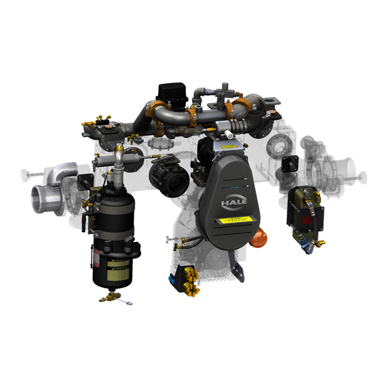
Page 14: Major Components And Controls
Page 14 of 116 MAJOR COMPONENTS AND CONTROLS GENERAL ARRANGEMENT CAFS Manifold Discharge Manifold Rotary Twin Screw Compressor Anodes [FSG-PL-01306] (2) Suction Suction Manifold (2) Discharge w/MIV Suction Manifold w/MIV & Fill Thief Plate Style Oil Cooler (Heat Exchanger) Compressor Oil Filter In Line Driven Gearbox Compressed Air / Oil w/Integrated Cooler and... -
Page 15: Smartcafs Mixing Manifold
Page 15 of 116 SMARTCAFS MIXING MANIFOLD (a) Volute Style Pump ARC (Air Ratio Control) Valve Mixing insert Foam Solution outlet outlet CAFS outlet Foam Double Check Valve Flow sensor Drain Air injection Water inlet Foam injection point Figure 3: DSD CAFS Mixing Manifold ©HALE PRODUCTS, INC. -
Page 16: B ) High Pressure
Page 16 of 116 Foam Check (b) High Pressure Valves Water inlet Flow sensor Foam Foam injection Solution Air injection Discharge point CAFS outlet ARC (Air Ratio Control) Valve CAFS check valve Mixing insert (not shown) (not shown) Figure 4: QTWO High Pressure CAFS Discharge (c) Standard Pressure Flow sensor Foam injection... -
Page 17: Foam Unit 3.3, 5.0, 6.5 Foam Pump Component Group
Page 17 of 116 FOAM UNIT 3.3, 5.0, 6.5 FOAM PUMP COMPONENT GROUP NOTE: Hale Foam unit 3.3, 5.0 or 6.5 foam pump is supplied loose for mounting by vehicle builder. Figure 6: Foam Pump Figure 7: In-Line Strainer Figure 8: Water Strainer Figure 9: ADT Selector Figure 10: MDT Selector Figure 11: MST Selector... -
Page 18: Control Panel - Smartcafs
Page 18 of 116 CONTROL PANEL - SMARTCAFS SmartCAFS Master Gauge Control Display (Optional) Audible Master Drain Air Overspeed Alarm Switch (Optional) Figure 15: SmartCAFS Testing Panel COMPONENT PANEL CUT-OUT DIMENSIONS Figure 16: Installation Cut-out Dimensions ©HALE PRODUCTS, INC. Our policy is one of continuous development. We therefore reserve the right to amend specifications without notice or obligation. -
Page 19: System Overview
Page 19 of 116 SYSTEM OVERVIEW The SmartCAFS is a Compressed Air Foam System comprising of two major components (in addition to the main water pump) – Air compressor system (with separate heat exchanger and oil/water separator) and Foam unit system (foam proportioning unit). The Foam unit foam pump and motor assembly is mounted separately from the water pump and is designed to be remotely mounted according to the Foam unit Installation... -
Page 20: Manifold
Page 20 of 116 MANIFOLD The manifold incorporates an ARC Valve [air ratio control valve] through which degrees of wet or dry foam mixture can be selected. Compressed air is then injected and the resulting foam / water / air combination is thoroughly mixed by the X-mixers during discharge. -
Page 21: Foam Unit 3.3, 5.0, 6.5 System - Remote Mounted
Page 21 of 116 FOAM UNIT 3.3, 5.0, 6.5 SYSTEM – REMOTE MOUNTED By-pass valve and connection point (on reverse of valve) To foam injection point on Figure 18: Foam unit 5.0 Pump manifold. 13mm (1/2inch) NPT Tubing suitable for 300PSI [22.5 bar] pressure Inlet from foam strainer, Models 3.3, 5.0 –... -
Page 22: Foam Unit Dimensions
Page 22 of 116 FOAM UNIT DIMENSIONS Figure 19: Installation Envelope Dimensions for 3.3 and 5.0 Foam Pumps Figure 20: Installation Envelope Dimensions for 6.5 12 VDC Foam Pump (Converter Installed) ©HALE PRODUCTS, INC. Our policy is one of continuous development. We therefore reserve the right to amend specifications without notice or obligation. - Page 23 Page 23 of 116 Figure 21: Installation Envelope Dimensions for 6.5 24 VDC Foam Pump ©HALE PRODUCTS, INC. Our policy is one of continuous development. We therefore reserve the right to amend specifications without notice or obligation.
-
Page 24: Installation And Initial Set-Up
Page 24 of 116 INSTALLATION AND INITIAL SET-UP The following connection points should be considered when installing the DSD SmartCAFS assembly into a vehicles frame. LIFTING POINTS Secure handling of the unit for installation and maintenance is vital. Use only the lifting points noted below. -
Page 25: Drive Line
Page 25 of 116 DRIVE LINE For driveline flange connection, appropriate driveline, shouldered Flange Series Qty. Size hardware in the quantity and size specified must be used. 1600, 1610 3/8” 1650, 1700 (9.5mm) 1710 Due to the increasing sophistication of fire apparatus and truck 1780, 1800 7/16”... - Page 26 Page 26 of 116 between the front and rear shafts changes every time the pump is used. Maximum Recommended Driveline Lengths lists the maximum driveline length using a safety factor of 42% of critical speed. This table is based on a 0.134” (3.4 mm) wall thickness. Shaft 2.0 (51) 2.5 (64)
-
Page 27: Pump Clearance
Page 27 of 116 PUMP CLEARANCE • Pump service area is depicted within the zones illustrated below. DSD unit pictured, but clearances for drive belt and anodes are common among all units. • A pump clearance plate is installed to the pump guard to ensure proper clearance for major pump service. -
Page 28: Panel Strainer
Page 28 of 116 PANEL STRAINER • The CAFS system cooling water strainer is mounted to the pump panel through a 2- 1/8” (54 mm) hole, with the supplied placard as shown in Figure 25. • Plumb 3/8” (9.5 mm) tubing between the tee, mounted on the bottom of the strainer, and the drain valve. -
Page 29: Compressor Connections
Page 29 of 116 COMPRESSOR CONNECTIONS • For reliable operation, the CAFS air filter must be located in a clean, fresh-air environment, usually in the dunnage area above the pump compartment. DO NOT damage the filter during assembly and be sure the mounting area offers protection. •... -
Page 30: Compressor Oil Service Access
Page 30 of 116 • A quick disconnect and ball valve should be installed on the panel to control air flow from aux air outlet. COMPRESSOR OIL SERVICE ACCESS • To allow access for compressor and pump servicing, a panel with approximately 450 square inches of area and no dimension less than 18”... -
Page 31: Fluid Drain Points
Page 31 of 116 Fluid Drain Points 1. For detailed operation, maintenance & care of the DSD SmartCAFS pump, refer to 8FG/DSD Series HIGH Volume Pumps; Operation and Maintenance Manual (Document number 029- 0020-93-0). For Q-Series, refer to 029-0020-63-0 Muscle Pump manual. 2. -
Page 32: Water Drain - Volute Style
Page 32 of 116 WATER DRAIN – VOLUTE STYLE Drain, Discharge Drain, Discharge Manifold Manifold Pump Water Drain Drain, Suction Drain, Suction Manifold Manifold Drain, Oil Cooler Drain, Discharge Foam Drain, Discharge CAFS (Optional) Master Water Drain ©HALE PRODUCTS, INC. Our policy is one of continuous development. We therefore reserve the right to amend specifications without notice or obligation. -
Page 33: Water Drain - Q-Series
Page 33 of 116 WATER DRAIN – Q-SERIES Drain, Discharge Foam Drain, Discharge CAFS Drain, Suction Drain, Suction Drain, Pump Drain, Oil Cooler (Optional) Master Water Drain ©HALE PRODUCTS, INC. Our policy is one of continuous development. We therefore reserve the right to amend specifications without notice or obligation. -
Page 34: System Oil Fill
Page 34 of 116 SYSTEM OIL FILL OIL FILLING POINTS The unit is supplied without oil and must be filled with the correct quantity and specification before starting the pump. ADDING OIL Before operating the CAFS system, oil must be added to the pump gearbox and the separator tank. -
Page 35: Oil Separator Tank
Page 35 of 116 OIL SEPARATOR TANK WARNING BEFORE RUNNING THE APPARATUS OR ENGAGING THE PUMP FOR THE FIRST TIME, MAKE SURE THE COMPRESSOR SYSTEM IS FILLED WITH THE APPROPRIATE OIL. AFTER THE INITIAL OIL FILL, ENGAGE THE PUMP AND ALLOW IT TO RUN FOR 10 SECONDS THEN SHUT THE SYSTEM DOWN. -
Page 36: Separator Tank For Compressor Oil
Page 36 of 116 Separator Tank for Compressor Oil Oil Fill Port MAXIMUM MINIMUM Water / Oil Drain, Oil Level Site Tube Separator Tank Figure 31: Separator Oil Fill and Drain Identification ©HALE PRODUCTS, INC. Our policy is one of continuous development. We therefore reserve the right to amend specifications without notice or obligation. -
Page 37: Hot-Shift Clutch Housing
Page 37 of 116 • Check system for oil leaks – repair any immediately. • If no leaks are present and oil level is correct, proceed with foam system calibration. HOT-SHIFT CLUTCH HOUSING • The Hot-Shift clutch housing is shipped from the factory with oil. -
Page 38: Schematics
Page 38 of 116 Schematics PLUMBING CONNECTIONS – DSD ©HALE PRODUCTS, INC. Our policy is one of continuous development. We therefore reserve the right to amend specifications without notice or obligation. - Page 39 Page 39 of 116 ©HALE PRODUCTS, INC. Our policy is one of continuous development. We therefore reserve the right to amend specifications without notice or obligation.
-
Page 40: Plumbing Connections - Q-Series
Page 40 of 116 PLUMBING CONNECTIONS – Q-SERIES ©HALE PRODUCTS, INC. Our policy is one of continuous development. We therefore reserve the right to amend specifications without notice or obligation. - Page 41 Page 41 of 116 ©HALE PRODUCTS, INC. Our policy is one of continuous development. We therefore reserve the right to amend specifications without notice or obligation.
-
Page 42: Smartcafs200 Interconnection Diagram - Dsd
Page 42 of 116 SMARTCAFS200 INTERCONNECTION DIAGRAM – DSD ©HALE PRODUCTS, INC. Our policy is one of continuous development. We therefore reserve the right to amend specifications without notice or obligation. -
Page 43: Smartcafs200 Interconnection Diagram - Q-Series
Page 43 of 116 SMARTCAFS200 INTERCONNECTION DIAGRAM – Q-SERIES ©HALE PRODUCTS, INC. Our policy is one of continuous development. We therefore reserve the right to amend specifications without notice or obligation. -
Page 44: Smartcafs200 Interconnection Diagram - All Units
Page 44 of 116 SMARTCAFS200 INTERCONNECTION DIAGRAM – ALL UNITS ©HALE PRODUCTS, INC. Our policy is one of continuous development. We therefore reserve the right to amend specifications without notice or obligation. -
Page 45: Foam Tank Low Level Sensor
Page 45 of 116 FOAM TANK LOW LEVEL SENSOR The unit is supplied with a connector for a low foam level sensor. The sensor is supplied with the unit ready for installation (instructions supplied with the sensor (Hale P/N: 200-2110-02-0). The low foam level sensor is part of the Safety Interlock system and must be installed. -
Page 46: Vehicle Design Considerations
Page 46 of 116 VEHICLE DESIGN CONSIDERATIONS The following information is included to assist the vehicle builder to achieve a successful installation. The in-line foam strainer / valve assembly is a low-pressure device, rated at 43PSI [.296 MPa] and will NOT withstand high flushing water pressure. -
Page 47: Commissioning / Start-Up Procedure
Page 47 of 116 COMMISSIONING / START-UP PROCEDURE Check that all the necessary connections have been correctly made. Ensure that the Compressed Air / Oil Separator Tank and pump gearbox are filled with the correct oil type and quantity. Prime and Run the water pump at 125 PSI [0.86 MPa] with compressor engaged. Run the compressor for 30 seconds to allow oil to circulate. -
Page 48: Optional Tank Selection For Foam Unit 3.3/5.0/6.5
Page 48 of 116 OPTIONAL TANK SELECTION FOR FOAM UNIT 3.3/5.0/6.5 For specific detail please refer to the Foam unit Model 3.3/5.0/6.5 Manual: Installation and Operation manual. For further information on the MDTII Manual Tank Selector, please see the separate manual supplied, part number 029-0020-40-0. -
Page 49: Optional Multi-Display Setup/Operation
Page 49 of 116 OPTIONAL MULTI-DISPLAY SETUP/OPERATION This is the setup and operation guide for the multi-display functionality of the SmartCAFS system. The multi-display feature is designed to work with up to 13 displays that can be placed around the truck to control the CAFS/Foam unit remotely. -
Page 50: B ) Operation
Page 50 of 116 Display Number 5. Once you have finished steps 1-4, press the save button. The display that was selected to be the default master will take you back to the home screen, and can be used as normal. The secondary displays will show the screen pictured below. -
Page 51: General Operation
Page 51 of 116 GENERAL OPERATION WARNING NEVER USE CAFS WITH A PRESSURE FEED INTO THE EYE OF THE PUMP. SMARTCAFS PUMPS SHOULD ONLY BE USED WHEN WORKING FROM OPEN WATER OR A TANK FEED. PROBLEMS WILL OCCUR WITH THE WATER / AIR PRESSURE RATIO, SHOULD PRESSURISED (HYDRANT) WATER SUPPLY BE APPLIED DIRECTLY TO THE SUCTION TUBE. -
Page 52: D ) Water Flow Display
Page 52 of 116 configuration screen allows the user to select the operating foam tank (A/B), foam percentage, CAFS mode, and ARC valve position. The operating screen is entered when a preset button is pressed and held for 0.5 seconds. The operating mode of the foam and CAFS will be set to the configured preset settings. -
Page 53: I ) Foam Percentage Indicator
Page 53 of 116 Foam percentage indicator The foam percentage indicator shows the foam proportioning rate for the currently selected tank. Foam power button The foam power button turns the foam system OFF or ON. The foam power button’s color indicates the currently selected foam tank (A green, B red, FLUSH orange). -
Page 54: O ) Air Display
Page 54 of 116 Air display This display shows the current air pressure, CAFS ratio, or current air flow rate based on the “CAFS air display” selection configured in the “user menu” (see section 0). The air flow rate and CAFS ratio displays are only shown when CAFS is turned ON. CAFS air/water flow ratio The CAFS air/water flow ratio is a bar graph that shows the relationship between the air flow and water flow rates (0% to 100%). -
Page 55: (U) Auto-Fill Manual Button
Page 55 of 116 Auto-fill manual button (When an auto-fill system is installed) The auto-fill manual button opens the KZCO valve connected to the inlet in order to fill the water tank. This button is a momentary button and the valve will only be open as long as the button is held. -
Page 56: Foam/Cafs Operation
Page 56 of 116 FOAM/CAFS OPERATION ENGAGE THE PUMP WARNING DO NOT APPLY HYDRANT PRESSURE TO PUMP SUCTION WHEN OPERATING CAFS. MAY BE OPERATED FROM OPEN WATER OR TANK FEED ONLY NOTE: The automatic tank-to-pump open function is a menu selectable item and must be set for “automatic: for this operation to occur (this is the default). -
Page 57: Increase Engine Speed For Desired Water Pressure
Page 57 of 116 The bottom left corner of the screen shows the currently active preset. INCREASE ENGINE SPEED FOR DESIRED WATER PRESSURE (With Sentry pressure governor) – The SmartCAFS Controller automatically communicates with the Sentry governor to set the governing system to RPM mode and ramp to its preset 1 engine speed. -
Page 58: Disengaging The Compressor Clutch
Page 58 of 116 CAFS wet Foam % dry buttons increase decrease buttons Manual is active The bottom left corner of the screen will now show “manual” because the settings have been changed from the original preset values. The foam and/or CAFS power buttons can be pressed to enable/disable the foam/CAF Systems. •... -
Page 59: Overheat Shut Down
Page 59 of 116 Foam power button NOTE: It will be necessary to turn OFF the foam system if foam operation is no longer desired. 3. Run water through the CAFS discharge system to flush out the foam agent. 4. Close the CAFS discharge valves. 5. -
Page 60: Optional Water Auto-Fill Operation
Page 60 of 116 OPTIONAL WATER AUTO-FILL OPERATION The SmartCAFS water Auto-Fill system attempts to maintain the desired water tank level by gating the KZCO valve on the inlet side of the pump. The system is controlled by the SmartCAFS display. The Auto-Fill system gets the tank level information from the Class1 ITL (Intelli-Tank) water gauge. -
Page 61: Enabling Auto-Fill
Page 61 of 116 Items not shown but included in kit: • Auto-Fill harness • 0-5 PSI Pressure Transducer • Tank Level ITL-4 • ITL-4 Harness The Auto-Fill Kit comes in 2 sizes, a 2.5” (538-00048-250) and 3.0” (538-00048-300) versions. ENABLING AUTO-FILL The Auto-Fill has to be enabled in the SmartCAFS controller’s USER menu (password 1849). -
Page 62: Manually Open The Auto-Fill Valve
Page 62 of 116 Auto-Fill Auto-Fill system OFF system ON MANUALLY OPEN THE AUTO-FILL VALVE Press the auto-fill manual button to force the valve open. Release the button to close the valve (if the auto-fill system is ON it will revert to the automatic control). A positive pressure water source is NOT required for the Auto-Fill valve to be opened manually. -
Page 63: Menus
Page 63 of 116 MENUS SYSTEM MENU Press and hold the MENU button for 3 seconds until the system menu is shown. The system menu allows the clearing (zero) of the total water and total foam display, setting the simulated water flow (for diagnostics), and entering passwords for other menus (user and OEM), for calibrations (water and foam), and for configuration (presets). -
Page 64: User Menu
Page 64 of 116 USER MENU Enter the password 1849 in the system menu’s keyboard to open the user menu. The user menu allows setting of user configurable items. Language - select the desired language to show within the SmartCAFS Controller. Default: English Unit of measure - select the desired unit of measure for the system (English or metric). -
Page 65: "+" And "-" Buttons
Page 65 of 116 “+” and “-“ buttons Change the value of the currently selected menu item. (aa) Exit button Exit the menu. (bb) Save button Save all items in the menu. OEM MENU Enter the password 2314 in the system menu’s keyboard to open the user menu. The user menu allows setting of user configurable items. -
Page 66: Cc ) Up/Down Arrow Buttons
Page 66 of 116 Displayed voltage calibration - if the displayed voltage in the additional information displays does not match the actual system voltage this value can be adjusted to calibrate (offset) the voltage (-1.5 to +1.5 volts). Default: 0.0 volts Warning inhibit timeout - sets the amount of time (30 to 300 seconds) that a warning, which was inhibited (cleared) by the operator, will stay hidden until it shown again (if the warning is still active). -
Page 67: Calibrations
Page 67 of 116 CALIBRATIONS Enter the password 6679 in the system menu’s keyboard to open the calibration menu. The calibration menu allows the foam and water calibrations to be performed. NOTE: Anytime the button is shown it can be pressed to pop-up a tutorial about the current screen. - Page 68 Page 68 of 116 2. Press the “chart icon” button to open the flow rate calculator. Chart icon 3. This calculator will allow the entry of the smooth bore nozzle size and the current pitot gauge reading in order to calculate the flow rate. Press the “return arrow icon” button to return to the water flow calibration screen.
- Page 69 Page 69 of 116 5. Press the “check mark” button on the desired side (high or low). Make sure that the value in the yellow “raw pulses” display window is now in the green “high pulses” (or “low pulses”) display window. Check mark 6.
-
Page 70: Water Flow Calibration (Direct)
Page 70 of 116 WATER FLOW CALIBRATION (DIRECT) The direct water flow calibration is simply a means of entering the values from a previous water flow calibration without the need to actually flow water. The direct water flow calibration requires the known values for the water flow value and its related water flow pulses (high and low) from a previously completed calibration. - Page 71 Page 71 of 116 4. The bar graph will increase to indicate that the foam pump is running and the system will begin discharging foam concentrate. The “total foam discharged” display will begin incrementing. Bar graph Total foam discharged 5. When the foam concentrate has filled the container to a known level press the power button again to stop the foam system.
- Page 72 Page 72 of 116 7. Press the “save” button. Press the “exit” button to return to the calibration menu. Exit Save Place the bypass handle back to the “inject” position. ©HALE PRODUCTS, INC. Our policy is one of continuous development. We therefore reserve the right to amend specifications without notice or obligation.
-
Page 73: Configuration
Page 73 of 116 CONFIGURATION PRESET CONFIGURATION (STANDARD) The SmartCAFS Controller allows up to 10 presets to be configured. These presets can be set for foam only or foam and air (CAFS). Enter the password 1023 in the system menu’s keyboard to open the preset configuration menu. Select the preset to configure and that preset’s configuration screen will be shown. -
Page 74: Preset Configuration (Live)
Page 74 of 116 PRESET CONFIGURATION (LIVE) Once a preset has been configured via the standard configuration it may not have produced the CAFS consistency desired. The “live” preset configuration allows the operator to flow CAFS while adjusting the consistency and then re-save that new value to the desired preset. Enter the password 40692 in the system menu’s keyboard to open the user menu. -
Page 75: On-Screen Warnings And Information
Page 75 of 116 ON-SCREEN WARNINGS AND INFORMATION The SmartCAFS Controller uses on-screen pop-up warnings and information to indicate system status to the operator. Figure 36: Warnings use a red background Figure 37: Information uses a blue background Touch the warning/information to dismiss it (inhibited). The warning will be hidden for the number of seconds set in the OEM menu’s “warning inhibit timeout.”... -
Page 76: Maintenance Minder
Page 76 of 116 MAINTENANCE MINDER This reminder in Figure 38 is only displayed at initial power up and won’t return until the next power cycle if maintenance is still due. Touch anywhere on the screen or any button to clear the reminder. Figure 38: Maintenance Reminder Warning Message Figure 39 shows the “maintenance minder”... - Page 77 Page 77 of 116 When maintenance is due it will be indicated by a fully red pie chart and the text “DUE”. Press the “i" button next to any maintenance interval to see what maintenance is required. Figure 41: Maintenance Minder with past due items The tutorial button (“i”...
-
Page 78: Routine Maintenance
Page 78 of 116 ROUTINE MAINTENANCE Between operations of the SmartCAFS unit make sure system components are filled with the proper grade and amount of oil. These components include the Air Compressor System and the Drive Unit Gearbox. The following procedures are provided to assist in the periodic maintenance of oil levels. For detailed maintenance instructions of individual components, refer to the maintenance and operation manuals that were supplied with the apparatus. -
Page 79: Air Compressor Moisture Drain
Page 79 of 116 AIR COMPRESSOR MOISTURE DRAIN After the air compressor system is used and has had time to COOL to ambient temperature, accumulated moisture must be drained from the oil reservoir separator. Drain Moisture To drain the moisture from the system, locate the oil and moisture drain valve on the bottom of the oil reservoir separator. -
Page 80: Oil And Oil Filter
Page 80 of 116 OIL AND OIL FILTER NOTE: The air compressor oil and oil filter must be changed every 100 hours of operation or when the apparatus engine oil is changed. To Change Oil and Oil Filter NOTE: Reference pages &... -
Page 81: Cooling Water Strainer
Page 81 of 116 WARNING ALWAYS ALLOW OIL TO SETTLE PRIOR TO CHECKING LEVEL. DO NOT OVERFILL THE SYSTEM. THE PROPER OIL LEVEL MUST BE MAINTAINED IN THE AIR COMPRESSOR SYSTEM AT ALL TIMES. LOW OIL LEVEL OR NO OIL COULD RESULT IN EXCESSIVE COMPRESSOR TEMPERATURE AND MAJOR DAMAGE. -
Page 82: Compressor Belt Maintenance
Page 82 of 116 COMPRESSOR BELT MAINTENANCE REMOVE BELT GUARD To expose the belt, the belt guard, 6 screws, and hardware must be removed. Belt Belt Guard Adjustment Bolts Figure 44: Belt Guard Location (DSD Shown) ATTENTION Proper belt tension is critical to long equipment life. A loose belt causes a knock or bang as the teeth jump. -
Page 83: Checking Belt Tension
Page 83 of 116 CHECKING BELT TENSION 1. Use a belt tension gauge to determine the tension applied to the belt and check on the left side of the unit (See Figure 45). 2. From the front tip of the gauge, measure back 5/ 16”... -
Page 84: Adjusting Belt Tension
Page 84 of 116 ADJUSTING BELT TENSION Figure 47: Belt Tension Adjustment Bolts 1. If the belt tension is less than required: a. Loosen the center bolt located in the middle of the compressor mounting bracket. (See Figure 47) b. Tighten two jacking studs located at both ends of the mounting bracket. 2. -
Page 85: Hot Shift Clutch Maintenance
Page 85 of 116 HOT SHIFT CLUTCH MAINTENANCE NOTE: The hot shift clutch oil should be changed every 100 hours of operation or when the apparatus engine oil is changed. (See Figure 48) Figure 48: Hot Shift Operation CHANGING CLUTCH OIL 1. -
Page 86: Maintenance Schedule For Smartcafs
Page 86 of 116 MAINTENANCE SCHEDULE FOR SMARTCAFS NOTE: The HALE service intervals replace those in the Gardner Denver Compressor manuals. Click below for Procedure W/ Internet EQUIPMENT ACTION Hyperlinks or Internal Page Links EVERY 3 MONTHS Check the pump and gearbox oil levels Page Do a vacuum test to test for leaks Page... -
Page 87: Maintenance Operations Pump - Smartcafs
Page 87 of 116 MAINTENANCE OPERATIONS PUMP – SMARTCAFS CAFS MIXING MANIFOLD – GREASING BALL VALVE The CAFS Mixing Manifold contains a ball valve as part of the air ratio control system. This ball valve must be maintained by inserting lubricating grease at three monthly intervals to ensure smooth and efficient operation. -
Page 88: Vacuum Test Pump Manifold
Page 88 of 116 VACUUM TEST PUMP MANIFOLD If the pump will not hold the vacuum with the blanking caps in position, a leak is present in the pump, and the pressure test detailed below must be carried out to trace it. Should the pump not reach a vacuum of 20inHg [0.7bar] but will hold a lower pressure, a fault in the priming system is indicated. -
Page 89: Cafs - Setting The Air Balance Control Valves
Page 89 of 116 CAFS - SETTING THE AIR BALANCE CONTROL VALVES Symptoms of Improper Adjustment a. Air pressure fluctuates or bounces too far from water pressure on the duplex gauge: i. The snubber valve is open too much b. A “popping” sound is observed within the air intake filter & ducting: i. - Page 90 Page 90 of 116 LOCK NUT FLOW SNUBBER ADJUSTABLE NUT Figure 50: Compressor Intake Adjustment g. Increase engine speed to 100 psi. Air pressure should follow. h. Increase engine speed to 125 psi. Air pressure should follow. i. Increase engine speed to 150 psi. Air pressure should follow. j.
-
Page 91: Cafs - Hot Shift Clutch Engagement
Page 91 of 116 CAFS – HOT SHIFT CLUTCH ENGAGEMENT The hot shift clutch is engaged when the CAFS switch is activated. a. Pressing the CAFS enable switch to engage the hot shift clutch. “ b. Pressing the on the screen or button for 3 seconds will disengage the hot shift clutch. -
Page 92: Recommended Spares Kit For Service
Page 92 of 116 RECOMMENDED SPARES KIT FOR SERVICE Unit Qty. Item Part Number Comment CAFS System Filter - Oil 010-0650-01-0 Filter - Air 010-0690-00-0 Separator Element Replacement Kit 010-0950-00-0 Compressor Oil SAE 15W-40HD Hot Shift Oil Dexron III or Mercon ATF Air Inject Valve 546-00058-000 PUMP... -
Page 93: Parts List
Page 93 of 116 PARTS LIST MAJOR ASSEMBLIES ©HALE PRODUCTS, INC. Our policy is one of continuous development. We therefore reserve the right to amend specifications without notice or obligation. - Page 94 Page 94 of 116 ©HALE PRODUCTS, INC. Our policy is one of continuous development. We therefore reserve the right to amend specifications without notice or obligation.
-
Page 95: Smartcafs200 Wiring Harness
Page 95 of 116 SMARTCAFS200 WIRING HARNESS ©HALE PRODUCTS, INC. Our policy is one of continuous development. We therefore reserve the right to amend specifications without notice or obligation. - Page 96 Page 96 of 116 ©HALE PRODUCTS, INC. Our policy is one of continuous development. We therefore reserve the right to amend specifications without notice or obligation.
-
Page 97: Thermal Relief Valve
Page 97 of 116 THERMAL RELIEF VALVE ©HALE PRODUCTS, INC. Our policy is one of continuous development. We therefore reserve the right to amend specifications without notice or obligation. -
Page 98: Parts List - Suction Manifold
Page 98 of 116 PARTS LIST – SUCTION MANIFOLD ©HALE PRODUCTS, INC. Our policy is one of continuous development. We therefore reserve the right to amend specifications without notice or obligation. -
Page 99: Parts List - Discharge Manifold
Page 99 of 116 PARTS LIST – DISCHARGE MANIFOLD ©HALE PRODUCTS, INC. Our policy is one of continuous development. We therefore reserve the right to amend specifications without notice or obligation. -
Page 100: Parts List - Belt Guard & Cafs Mixing Manifold
Page 100 of 116 PARTS LIST – BELT GUARD & CAFS MIXING MANIFOLD ©HALE PRODUCTS, INC. Our policy is one of continuous development. We therefore reserve the right to amend specifications without notice or obligation. -
Page 101: Parts List - Oil Filter & Strainer
Page 101 of 116 PARTS LIST – OIL FILTER & STRAINER ©HALE PRODUCTS, INC. Our policy is one of continuous development. We therefore reserve the right to amend specifications without notice or obligation. -
Page 102: Parts List - Compressor
Page 102 of 116 PARTS LIST – COMPRESSOR ©HALE PRODUCTS, INC. Our policy is one of continuous development. We therefore reserve the right to amend specifications without notice or obligation. - Page 103 Page 103 of 116 ©HALE PRODUCTS, INC. Our policy is one of continuous development. We therefore reserve the right to amend specifications without notice or obligation.
-
Page 104: Parts List - Separator, Oil Reservoir
Page 104 of 116 PARTS LIST – SEPARATOR, OIL RESERVOIR ©HALE PRODUCTS, INC. Our policy is one of continuous development. We therefore reserve the right to amend specifications without notice or obligation. - Page 105 Page 105 of 116 ©HALE PRODUCTS, INC. Our policy is one of continuous development. We therefore reserve the right to amend specifications without notice or obligation.
-
Page 107: Quick Reference Guide/Troubleshooting
Page 107 of 116 QUICK REFERENCE GUIDE/TROUBLESHOOTING AIR INJECTION/CONTROL PART 12V: 038-00043-010 NUMBER 24V: 038-00043-000 DESCRIPTION Air Inject Solenoid Controls the air supply to the air inject valve. When the air is supplied to the air OPERATION valve it allows air to be injected into the system. - Page 108 Page 108 of 116 PART 038-00109-000 NUMBER DESCRIPTION Air Pressure Limiter This relief valve is to be set at 170-175 OPERATION PSI. It limits the max air pressure the system can produce. • Air pressure not sufficient Pressure limiter limiting the max air pressure allowed.
- Page 109 Page 109 of 116 PART 038-1560-00-0 NUMBER DESCRIPTION Blow Down Valve Releases built up pressure in air system. Air pressure is supplied from the oil OPERATION separator and the air intake. If they don’t match the valve opens connection from the oil separator to atmosphere Air leaks •...
-
Page 110: Compressor Operation
Page 110 of 116 PART 038-1680-01-0 NUMBER DESCRIPTION Air Intake Inlet Needle Valve This valve controls the amount of air pressure dumping to atmosphere. The OPERATION more air dumping the farther the air intake plunger opens. Air flow for wet is too great •... - Page 111 Page 111 of 116 PART 538-00107-000 NUMBER DESCRIPTION Cooler Valve Cooling water from the heat exchanger designed to cool the compressor is plumbed to the tank. When not running OPERATION CAFS (i.e. drafting), the tank can overfill. This solenoid/valve assembly is designed to be flowing when the clutch solenoid is engaged.
- Page 112 Page 112 of 116 PART 200-1161-00-0 NUMBER DESCRIPTION Oil Temperature Sensor Temperature sensor enables/disables the compressor interlock. If temperature goes OPERATION outside of operating range or if system loses signal from this sensor then the clutch will be disabled. • Clutch is not engaging POSSIBLE No signal from this sensor.
- Page 113 Page 113 of 116 PART 12V: 538-1910-10-0 NUMBER 24V: 538-1910-00-0 DESCRIPTION Clutch Enable Solenoid The clutch solenoid is normally closed. When all of the interlock conditions are OPERATION met the solenoid opens and allows air to engage the clutch. • Clutch is not engaging Clutch solenoid has failed Solenoid not receiving signal POSSIBLE...
-
Page 114: Cafs Operation
Page 114 of 116 PART 200-2610-00-0 NUMBER DESCRIPTION Tachometer Tachometer reads the rotation of the drive shaft. It reports to the UV SmartCAFS OPERATION display order meet interlock requirements for the clutch enable. • Clutch is not engaging Engine speed is too high POSSIBLE Tachometer has failed FAULT... - Page 115 Page 115 of 116 PART STANDARD: 102714 NUMBER HIGH PRESSURE KIT: 8713198-1 DESCRIPTION Paddlewheel Paddlewheel measures the water flow before foam and air injection. The high OPERATION pressure kit is for qtwo and other high pressure pump applications. No signal from paddlewheel can •...
-
Page 116: Limited Warranty
Page 116 of 116 LIMITED WARRANTY Express Warranty EXPRESS WARRANTY: Hale Products, Inc. (HALE) hereby warrants to the original Buyer that products manufactured by Hale are free of defects in material and workmanship for one (1) year. The “Warranty Period” commences on the date the original Buyer takes delivery of the product from the manufacturer.
Need help?
Do you have a question about the HALE SmartCAFS and is the answer not in the manual?
Questions and answers