Table of Contents
Advertisement
Quick Links
PLEASE NOTE!
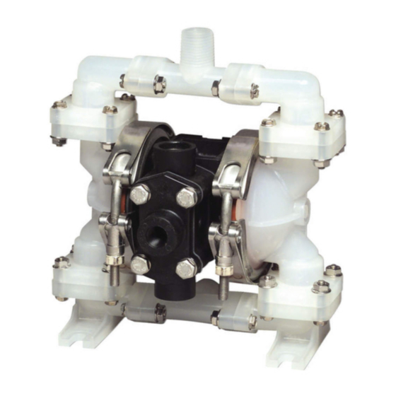
The photos shown in this manual are for general instruction only. YOUR SPECIFIC
MODEL MAY NOT BE SHOWN. Always refer to the parts list and exploded view
drawing for your specific model when installing, disassembling or servicing your
pump.
PRINCIPLE OF PUMP OPERATION
This ball type check valve pump is powered by compressed air and is a 1:1
pressure ratio design. It alternately pressurizes the inner side of one diaphragm
chamber, while simultaneously exhausting the other inner chamber. This causes the
diaphragms, which are connected by a common rod, to move endwise. Air pressure
is applied over the entire surface of the diaphragm, while liquid is discharged from the
opposite side. The diaphragm operates under a balanced condition during the
discharge stroke, which allows the unit to be operated at discharge heads over 200
feet (61 meters) of water head.
Since the diaphragms are connected by a common rod, secured by plates to the
center of the diaphragms, one diaphragm performs the discharge stroke, while the
other is pulled to perform the suction stroke in the opposite chamber.
For maximum diaphragm life, keep the pump as close to the liquid being pumped
as possible. Positive suction head in excess of 10 feet of liquid (3.048 meters) may
require a back pressure regulating device. This will maximize diaphragm life.
Alternate pressuring and exhausting of the diaphragm chamber is performed by
means of an externally mounted, pilot operated, four-way spool type air distribution
valve. When the spool shifts to one end of the valve body, inlet air pressure is applied
to one diaphragm chamber and the other diaphragm chamber exhausts. When the
spool shifts to the opposite end of the valve body, the porting of chambers is reversed.
The air distribution valve spool is moved by an internal pilot valve which alternately
pressurizes one side of the air distribution valve spool, while exhausting the other side.
The pilot valve is shifted at each end of the diaphragm stroke by the diaphragm plate
coming in contact with the end of the pilot spool. This pushes it into position for shifting
of the air distribution valve.
The chambers are manifolded together with a suction and discharge check valves
for each chamber, maintaining flow in one direction through the pump.
INSTALLATION & START-UP
Locate the pump as close to the product being pumped as possible, keeping
suction line length and number of fittings to a minimum. Do not reduce line size.
For installations of rigid piping, short flexible sections of hose should be installed
between pump and piping. This reduces vibration and strain to the piping system. A
Warren Rupp surge suppressor is recommended to further reduce pulsation in flow.
This pump was tested at the factory prior to shipment and is ready for operation.
It is completely self-priming from a dry start for suction lifts of 10-15 feet (3 to 4.5
meters) or less. For suction lifts exceeding 15 feet of liquid, fill the chambers with liquid
prior to priming.
AIR SUPPLY
Air supply pressures cannot exceed 100 psi (7 bar). Connect the pump air inlet
(see Fig. 1) to an air supply of sufficient capacity and pressure required for desired
performance. When the air line is solid piping, use a short length of flexible hose not
3
less than
/
" (19mm) in diameter between pump and piping to eliminate strain to pipes.
4
The weight of the air supply line and of the filter must be supported by some means
other than the air valve cap. Failure to provide support may result in damage to the
pump. A pressure regulating valve should be installed to prevent pressure from
exceeding recommended limits.
Warren Rupp, Inc., A Unit of IDEX Corp • P.O. Box 1568 • Mansfield, Ohio 44901-1568 USA • (419) 524-8388 • Fax (419) 522-7867
520-032-000 5/99
SERVICE AND OPERATING MANUAL
®
Model PB1-A
Type 3
CAUTION
Hydrofluoric acid above 40% concen-
trate should not be pumped with this
unit. Check chemical compability chart
for other fluids.
CAUTION
Maximum Operating Pressure, 100 P.S.I.
(7 Bar.) and Safe Operating Temp-
eratures of 150°F. (66°C.) Maximum and
40°F. (4.4°C.) Minimum are based upon
mechanical stress only and may be
significantly altered by pumping certain
chemicals. Consult engineering guides
for chemical compatibilities and
temperature limits.
IMPORTANT
Read these instructions completely,
before installation and start-up. It is the
responsibility of the purchaser to retain
this manual for reference. Failure to
comply with the recommendations
stated in this manual will damage the
pump, and void factory warranty.
WARNING
Take action to prevent static sparking.
Fire or explosion can result, especially
when handling flammable liquids. The
pump, piping, valves, containers or other
miscellaneous equipment must be
grounded.
BEFORE OPERATION
Before pump operation, inspect all
gasketed fasteners for looseness caused
by gasket creep. Retorque loose fasten-
ers to prevent leakage. Follow recom-
mended torques stated in the card at-
tached to the new pump.
DANGER
Before doing any maintenance on the
pump, be certain all pressure is com-
pletely vented from the pump, suction,
discharge, piping, and all other open-
ings and connections. Be certain the air
supply is locked out or made non-
operational, so that it cannot be started
while work is being done on the pump.
Be certain that approved eye protection
and protective clothing are worn at all
times in the vicinity of the pump. Failure
to follow these recommendations may
result in serious injury or death.
PB1-A Type 3 Page 1
Advertisement
Table of Contents

Subscribe to Our Youtube Channel
Related Manuals for Idex WARREN RUPP SandPIPER PB1-A


Summary of Contents for Idex WARREN RUPP SandPIPER PB1-A
- Page 1 Warren Rupp, Inc., A Unit of IDEX Corp • P.O. Box 1568 • Mansfield, Ohio 44901-1568 USA • (419) 524-8388 • Fax (419) 522-7867 520-032-000 5/99 PB1-A Type 3 Page 1...
- Page 2 AIR INLET & PRIMING For start-up, open an air valve approximately turn. After the unit primes, an air valve can be opened to increase flow as desired. If opening the valve increases cycling rate, but does not increase flow rate, cavitation has occurred, and the valve should be closed slightly.
- Page 3 allowing the diaphragm to turn freely with plates. Use a wrench on the outer diaphragm plate of the opposite side to keep rod from rotating. If the opposite chamber is assembled, the rod need not be held. A Note about Air Valve Lubrication The pump’s pilot valve and main air valve assemblies are designed to operate WITHOUT lubrication.
- Page 4 care that the bumper stays in place allowing the sleeve to press in all the way. Re- CAUTION install the spool, opposite end cap, gasket and bumper on the valve body. After In the event of diaphragm rupture, inspecting and cleaning the gasket surfaces on the valve body and intermediate, re- pumped material may enter the air end install the valve body on the pump using new gaskets.
- Page 5 TROUBLESHOOTING CAUTION 1. Pump will not cycle In the event of diaphragm rupture, A. Check to make sure the unit has enough pressure to operate and that the air inlet pumped material may enter the air end valve is open. of the pump, and be discharged into the B.
- Page 6 Order P/N 031-060-000 which also includes items 5, 7, 8, 12, 23 & 55. Warren Rupp, Inc., A Unit of IDEX Corp • P.O. Box 1568 • Mansfield, Ohio 44901-1568 USA • (419) 524-8388 • Fax (419) 522-7867 520-032-000 5/99...
- Page 7 ITEM TOTAL Repair Parts shown in bold face (darker) type are more likely to need replacement PART NUMBER DESCRIPTION RQD. after extended periods of normal use. They are readily available from most Warren Rupp distributors. The pump 196-056-551 Chamber, Outer owner may prefer to maintain a limited 722-043-551 Seat, Ball...
- Page 8 OVERLAY OVERLAY OVERLAY OVERLAY OVERLAY TYPES TYPES TYPES TYPES TYPES ONLY ONLY ONLY ONLY ONLY © 1999 Warren Rupp, Inc. All rights reserved. Printed in U.S.A. WARREN RUPP, Inc. • P.O. Box 1568 • Mansfield, Ohio 44901-1568 USA • (419) 524-8388 • Fax (419) 522-7867 520-032-000 5/99 PB1-A Type 3 Page 8...
Need help?
Do you have a question about the WARREN RUPP SandPIPER PB1-A and is the answer not in the manual?
Questions and answers