Table of Contents
Advertisement
Quick Links
Models: PC1_ or PC2_ with FoamLogix 2.1A, 3.3, 5.0, 6.5 Systems
Godiva Ltd.
A Unit of IDEX Corporation
Charles St
Warwick CV34 5LR
England
+44 (0)1926 623600
+44 (0)1926 623666 / 623689
www.godiva.co.uk
godiva@idexcorp.com
Prima
and SmartCAFS50, 100, 200 Control
Maintenance Manual
Pump with Integrated
GP/274
Issue 5, September 2014
Advertisement
Chapters
Table of Contents
Troubleshooting

Related Manuals for Idex Godiva Prima PC1 2010


Summary of Contents for Idex Godiva Prima PC1 2010
- Page 1 Pump with Integrated Models: PC1_ or PC2_ with FoamLogix 2.1A, 3.3, 5.0, 6.5 Systems and SmartCAFS50, 100, 200 Control Maintenance Manual Godiva Ltd. A Unit of IDEX Corporation Charles St Warwick CV34 5LR England +44 (0)1926 623600 +44 (0)1926 623666 / 623689 ...
- Page 2 AMENDMENT RECORD Model: PC1_ or PC2_ with FoamLogix 2.1A, 3.3, 5.0 or 6.5 Systems and SmartCAFS50, 100 or 200 Control Mod Date Page/s Amendment New Issue No. September New Issue Issue 1, 2010 Item 1 – run compressor for 15 minutes to October 2010 Issue 2 remove water.
- Page 3 CONTENTS AMENDMENT RECORD ....................2 CONTENTS ........................3 1. INTRODUCTION ....................... 6 PUMP SERIAL NUMBER ..................6 MODEL IDENTIFICATION ..................6 IMPORTANT NOTES ....................7 2. DESCRIPTION ......................8 COMPRESSOR ......................8 CAFS MANIFOLD ( ) ................9 ALL MODELS FOAMLOGIX - FOAM PROPORTIONING SYSTEM ..........
- Page 4 CHECK OIL LEVEL AND 15 MINUTE RUNNING – T 3 ........ 31 EMPEST CHECK OIL LEVEL AND 15 MINUTE RUNNING – T 6 ........ 32 EMPEST CHECK OIL LEVEL AND 15 MINUTE RUNNING – E 12 ....... 33 NDURO CHECK THE COMPRESSOR DRIVE BELT – T 3........
- Page 5 THE AIR INJECT SOLENOID VALVE ..............91 AIR VALVE AND SOLENOID VALVE ..............92 FOAMLOGIX FOAM PUMP ..................93 PRESSURE BALANCE VALVE ................94 PRESSURE BALANCE VALVE – PRESSURE SWITCH ........95 MANIFOLD NON-RETURN VALVES ..............96 FLOW SWITCH ....................... 97 PRESSURE SWITCH A AND B –...
- Page 6 INTRODUCTION This document contains preventive and corrective maintenance procedures for Godiva single or multi-pressure Prima Pumps equipped with Compressed Air Foam Systems (CAFS), FoamLogix Models 2.1A, 3.3, 5.0 or 6.5 and the SmartCAFS50, 100 or 200 control system. Differences between these models are clearly identified in the relevant procedures.
- Page 7 P C 2 A 2010/301 XX = numerical variation 3 = Piston primer system 2010 = 2000 l/min @ 10 bar - main pump output Other models – 3010, 4010 A = Aluminium B = Bronze 1 = Single pressure 2 = Twin pressure Compressed air foam Godiva Prima series pump IMPORTANT NOTES...
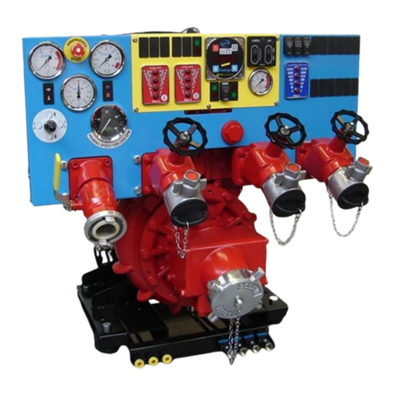
- Page 8 DESCRIPTION The PC1_ or PC2_ is a Compressed Air Foam System comprising three main components (in addition to the water pump) – Air Compressor, FoamLogix (foam proportioning unit) and Manifold (foam mixing and control system). The FoamLogix components (foam pump and motor assembly) are mounted separately from the water pump and are designed to be remotely mounted according to the vehicle builder’s requirements.
- Page 9 When the compressor is stationary, residual system pressure is vented by a blow-down valve. NOTE: The compressor must not be run without cooling water. CAFS MANIFOLD (all models) The manifold incorporates an air ratio control valve through which varying degrees of water/foam can be selected.
- Page 10 SAFETY PRECAUTIONS INTRODUCTION The equipment manufactured by Godiva Ltd has been designed with safety in mind. Where hazards cannot be eliminated, the risk has been minimised by the use of guards and other design features. Some hazards cannot be guarded against so the instructions on the equipment are responsible for safe working practices at all times.
- Page 11 EQUIPMENT HAZARDS AND SAFETY INSTRUCTIONS The safety instructions listed below have been categorised in relation to each hazard type that may occur. Some hazards listed may not occur on the specific equipment supplied, but are included to cover potential hazards that may be encountered with equipment of this type.
- Page 12 Noise Ear defenders must be worn when the equipment is running if the noise level exceeds the defined safe level. Make sure that any audible alarm or warning signal can still be heard when wearing ear defenders. Fibrous Materials A mask or respirator must be worn when working with components that contain fibrous material as these can be hazardous if fibrous dust is inhaled.
- Page 13 GENERAL DATA COMPRESSOR Used with Prima SmartCAFS50 (50scfm rating) - Model Tempest 3 Maximum Operating Speed 10000 rev/min Nominal speed of operation 6250 rev/min Nominal power consumption 12.0kW Direction of rotation Anti-clockwise (viewed on pulley) Volume output 1420 l/min 4 – 10 bar Operational pressure range Cooling system Oil/water shell and lube type...
- Page 14 FOAM PROPORTIONING SYSTEM 2.1A - CLASS A FOAM COMPATIBLE Manufacturer Hale Products Inc. Model FoamLogix 2.1A Type Electronic foam proportioning system Operating voltage 12 or 24 volt systems as specified Fuse rating 12V / 24V 50 / 40 amp Current draw (Operating) 12V / 24V 25 / 13 amp Current draw (Max) 12V / 24V 40 / 20 amp...
- Page 15 FOAM PROPORTIONING SYSTEM 6.5 – CLASS A AND B FOAM COMPATIBLE Manufacturer Hale Products Inc Model FoamLogix 6.5 Type Electronic foam proportioning system Operating voltage 12 and 24 volt systems available Fuse rating 12V / 24V 60 / 40 amp Current draw (Operating) 12V / 24V 30 / 15 amp Current draw (Max) 12V / 24V...
- Page 16 PERFORMANCE DATA PC1_ Performance Data 2010 3010 4010 6010 Priming Performance Range To 7.5m To 7.5m To 7.5m To 7.5m Priming Speed (recommended) 2500 rev/min 2500 rev/min 2500 rev/min 2500 rev/min Maximum Suction Pressure 12 bar 12 bar 12 bar 12 bar Maximum Recommended Speed 3600 rev/min...
- Page 17 PERFORMANCE DATA PC2_ Performance Data 2010 3010 4010 6010 Priming Performance Range To 7.5m To 7.5m To 7.5m To 7.5m Priming Speed (recommended) 2500 rev/min 2500 rev/min 2500 rev/min 2500 rev/min Maximum Suction Pressure 12 bar 12 bar 12 bar 12 bar Maximum Recommended Speed 3600 rev/min...
- Page 18 CROSS SECTION OF TYPICAL PRIMA PUMP P2 pump shown High /Low pressure transfer chamber and filter Low pressure discharge manifold Serial number (six figures stamped Drive flange onto volute casting) Tank to pump Pump inlet connection points Low pressure impeller Pump shaft seal High pressure impeller mechanism...
- Page 19 CROSS SECTION OF TYPICAL PRIMA PUMP P1 pump shown Priming valve Oil fill/level check cap Discharge manifold Tachometer Serial number (six figures stamped onto volute casting) Pump shaft Drive flange Tank to pump connection points Pump inlet Pump shaft seal Low pressure impeller mechanism Volute drain point...
- Page 20 MAINTENANCE INTRODUCTION WARNING! BEFORE WORKING ON THE EQUIPMENT, THE SECTION ON SAFETY MUST BE CAREFULLY READ, UNDERSTOOD AND STRICTLY ADHERED TO. Godiva Ltd equipment will provide many years of trouble-free service when maintained in accordance with the preventive maintenance schedule and operations specified in this manual.
- Page 21 OPERATING FLUIDS To ensure optimum performance and equipment life, use only the lubricant and foam concentrates specified in this manual. Never mix different grades/makes of oil or foam concentrates. They are manufactured for a specific duty, and mixing different grades/makes may result in adverse chemical reactions that result in loss of quality.
- Page 22 SERVICE KIT For Maintenance up to 24 Months QUANTITY SPARE PART PART NUMBER COMMENT Compressor – Tempest 3 Separator element 59271/02 Oil Filter 59271/01 Air Filter 59271 Drive Belt 60578/01 Drive Belt Tensioner 60579 Compressor – Tempest 6 Separator element TAM-03498328 TAM-89675429 Oil Filter...
- Page 23 SPECIAL TOOLS FOR PRIMER SERVICING QUANTITY TOOL DESCRIPTION PART NUMBER Piston Seal Assembly Tool comprising: - 65239/65240 Cone Locator 65239 Seal Expander 65240 Cylinder Support Tool 65466 Circlip Fitting Tool 65436 Circlip Drift Tool 65467 EQUIPMENT MAINTENANCE LOG Pump Serial Number ..... Use this log to record faults, part replacements and major overhauls.
- Page 24 PREVENTIVE MAINTENANCE INTRODUCTION WARNING! BEFORE WORKING ON THE EQUIPMENT, THE SECTION ON SAFETY MUST BE CAREFULLY READ, UNDERSTOOD AND STRICTLY ADHERED TO. WARNING! FAILURE COMPLY WITH PREVENTIVE MAINTENANCE SCHEDULE AND RELATED PROCEDURES IN THIS MANUAL MAY RESULT IN SERIOUS PERSONAL INJURY AND/OR DAMAGE TO THE EQUIPMENT.
- Page 25 PREVENTIVE MAINTENANCE SCHEDULE WARNING! BEFORE WORKING ON THE EQUIPMENT, THE SECTION ON SAFETY MUST BE READ, UNDERSTOOD AND ADHERED TO. WARNING! FAILURE COMPLY WITH PREVENTIVE MAINTENANCE SCHEDULE AND PROCEDURES IN THIS MANUAL MAY INVALIDATE THE WARRANTY AND RESULT IN PERSONAL INJURY AND/OR DAMAGE TO THE EQUIPMENT.
- Page 26 PREVENTIVE MAINTENANCE PROCEDURE PM-001 EVERY 3 MONTHS FREQUENCY Back to EQUIPMENT Pumps PC1_ / PC2_ Schedule Gearbox CHECK THE PUMP AND GEARBOX OIL LEVELS CHECK THE PUMP OIL LEVEL – Prima SmartCAFS50,100 WARNING! BEFORE WORKING ON THE EQUIPMENT, MAKE SURE THAT IT IS ISOLATED AND WARNING NOTICES ARE DISPLAYED.
- Page 27 CHECK THE PUMP OIL LEVEL – Prima SmartCAFS200 WARNING! BEFORE WORKING ON THE EQUIPMENT, MAKE SURE THAT IT IS ISOLATED AND WARNING NOTICES ARE DISPLAYED. WARNING! EQUIPMENT WILL REMAIN HOT AFTER THE PUMP HAS STOPPED. WAIT FOR IT TO COOL BEFORE MAINTENANCE STARTS. Prima SmartCAFS200 model shown.
- Page 28 CHECK THE GEARBOX OIL LEVEL – Prima SmartCAFS50, 100, 200 Note: Certain earlier pump models are fitted with a dipstick to check the gearbox oil level. Later models use the oil level plug on the side of the gearbox. WARNING! BEFORE WORKING ON THE EQUIPMENT, MAKE SURE THAT IT IS ISOLATED AND WARNING NOTICES ARE DISPLAYED.
- Page 29 PREVENTIVE MAINTENANCE PROCEDURE PM-002 EVERY 3 MONTHS FREQUENCY Back to Schedule EQUIPMENT Pumps PC1_ / PC2_ All models VACUUM TEST Do this test to check for leaks in the system. WARNING! BEFORE WORKING ON THE EQUIPMENT, MAKE SURE THAT IT IS ISOLATED AND WARNING NOTICES ARE DISPLAYED.
- Page 30 PREVENTIVE MAINTENANCE PROCEDURE PM-003 EVERY 3 MONTHS FREQUENCY Back to Schedule EQUIPMENT Pump PC2_ Only HIGH PRESSURE FILTER WARNING! BEFORE WORKING ON THE EQUIPMENT, MAKE SURE THAT IT IS ISOLATED AND WARNING NOTICES ARE DISPLAYED. WARNING! EQUIPMENT WILL REMAIN HOT AFTER THE PUMP HAS STOPPED.
- Page 31 PREVENTIVE MAINTENANCE PROCEDURE PM-004 EVERY 3 MONTHS FREQUENCY Back to Schedule Compressor – Tempest 3 EQUIPMENT CHECK OIL LEVEL AND 15 MINUTE RUNNING – Tempest 3 WARNING! BEFORE WORKING ON THE EQUIPMENT, MAKE SURE THAT IT IS ISOLATED AND WARNING NOTICES ARE DISPLAYED. WARNING! EQUIPMENT WILL REMAIN HOT AFTER THE PUMP HAS STOPPED.
- Page 32 PREVENTIVE MAINTENANCE PROCEDURE PM-004 EVERY 3 MONTHS FREQUENCY Back to Schedule EQUIPMENT Compressor - Tempest 6 CHECK OIL LEVEL AND 15 MINUTE RUNNING – Tempest 6 WARNING! BEFORE WORKING ON THE EQUIPMENT, MAKE SURE THAT IT IS ISOLATED AND WARNING NOTICES ARE DISPLAYED. WARNING! EQUIPMENT WILL REMAIN HOT AFTER THE PUMP HAS STOPPED.
- Page 33 PREVENTIVE MAINTENANCE PROCEDURE PM-004 EVERY 3 MONTHS FREQUENCY Back to Schedule Compressor – Enduro 12 EQUIPMENT CHECK OIL LEVEL AND 15 MINUTE RUNNING – Enduro 12 WARNING! BEFORE WORKING ON THE EQUIPMENT, MAKE SURE THAT IT IS ISOLATED AND WARNING NOTICES ARE DISPLAYED. WARNING! EQUIPMENT WILL REMAIN HOT AFTER THE PUMP HAS STOPPED.
- Page 34 PREVENTIVE MAINTENANCE PROCEDURE PM-005 EVERY 3 MONTHS FREQUENCY Back to Schedule Compressor – Tempest 3 EQUIPMENT CHECK THE COMPRESSOR DRIVE BELT – Tempest 3 WARNING! BEFORE WORKING ON THE EQUIPMENT, MAKE SURE THAT IT IS ISOLATED AND WARNING NOTICES ARE DISPLAYED. WARNING! EQUIPMENT WILL REMAIN HOT AFTER THE PUMP HAS STOPPED.
- Page 35 1. Tighten the belt so it is reasonably taut. 2. Operate the optical belt tensioner according to the manufacturer’s instructions. The device will register a frequency reading when the belt has been tapped. It is recommended several reading are taken to obtain a representative figure. 3.
- Page 36 PREVENTIVE MAINTENANCE PROCEDURE PM-005 EVERY 3 MONTHS FREQUENCY Back to Schedule Compressor – Tempest 6 EQUIPMENT CHECK THE COMPRESSOR DRIVE BELT – Tempest 6 WARNING! BEFORE WORKING ON THE EQUIPMENT, MAKE SURE THAT IT IS ISOLATED AND WARNING NOTICES ARE DISPLAYED. WARNING! EQUIPMENT WILL REMAIN HOT AFTER THE PUMP HAS STOPPED.
- Page 37 1. Tighten the belt so it is reasonably taut. 2. Operate the optical belt tensioner according to the manufacturer’s instructions. The device will register a frequency reading when the belt has been tapped. 3. It is recommended several readings are taken to obtain a representative figure. 4.
- Page 38 PREVENTIVE MAINTENANCE PROCEDURE PM-005 EVERY 3 MONTHS FREQUENCY Back to Schedule Compressor – Enduro 12 EQUIPMENT CHECK THE COMPRESSOR DRIVE BELT – Enduro 12 WARNING! BEFORE WORKING ON THE EQUIPMENT, MAKE SURE THAT IT IS ISOLATED AND WARNING NOTICES ARE DISPLAYED. WARNING! EQUIPMENT WILL REMAIN HOT AFTER THE PUMP HAS STOPPED.
- Page 39 Optical Belt Tension Meter If an optical belt tension meter is available, e.g. the Clavis Optical Belt Tensioner, then the belt can be tightened correctly by measuring the vibration frequency. Follow these steps – 1. Tighten the belt so it is reasonably taut. 2.
- Page 40 PREVENTIVE MAINTENANCE PROCEDURE PM-006 EVERY 3 MONTHS FREQUENCY Back to Schedule EQUIPMENT FoamLogix 2.1A, 3.3, 5.0, CHECK FOAM PIPE CONNECTIONS WARNING! BEFORE WORKING ON THE EQUIPMENT, MAKE SURE THAT IT IS ISOLATED AND WARNING NOTICES ARE DISPLAYED. WARNING! EQUIPMENT WILL REMAIN HOT AFTER THE PUMP HAS STOPPED.
- Page 41 PREVENTIVE MAINTENANCE PROCEDURE PM-007 EVERY 3 MONTHS FREQUENCY Back to Schedule EQUIPMENT FoamLogix 2.1A, 3.3, 5.0, OPERATING THE FOAMLOGIX SYSTEM WARNING! BEFORE WORKING ON THE EQUIPMENT, MAKE SURE THAT IT IS ISOLATED AND WARNING NOTICES ARE DISPLAYED. WARNING! EQUIPMENT WILL REMAIN HOT AFTER THE PUMP HAS STOPPED.
- Page 42 PREVENTIVE MAINTENANCE PROCEDURE PM-008 EVERY 12 MONTHS FREQUENCY Back to Schedule EQUIPMENT Pumps PC1_ / PC2_ CAFS50, 100 CHANGE THE BEARING HOUSING OIL WARNING! BEFORE WORKING ON THE EQUIPMENT, MAKE SURE THAT IT IS ISOLATED AND WARNING NOTICES ARE DISPLAYED. WARNING! EQUIPMENT AND LUBRICANT WILL REMAIN HOT AFTER THE PUMP HAS STOPPED.
- Page 43 PREVENTIVE MAINTENANCE PROCEDURE PM-008 EVERY 12 MONTHS FREQUENCY Back to Schedule EQUIPMENT Pumps PC1_ / PC2_ CAFS200 CHANGE THE BEARING HOUSING OIL WARNING! BEFORE WORKING ON THE EQUIPMENT, MAKE SURE THAT IT IS ISOLATED AND WARNING NOTICES ARE DISPLAYED. WARNING! EQUIPMENT AND LUBRICANT WILL REMAIN HOT AFTER THE PUMP HAS STOPPED.
- Page 44 PREVENTIVE MAINTENANCE PROCEDURE PM-009 EVERY 12 MONTHS FREQUENCY Back to Schedule Compressor – Tempest 3 EQUIPMENT CHANGE THE COMPRESSOR AIR FILTER – Tempest 3 WARNING! BEFORE WORKING ON THE EQUIPMENT, MAKE SURE THAT IT IS ISOLATED AND WARNING NOTICES ARE DISPLAYED. WARNING! EQUIPMENT WILL REMAIN HOT AFTER THE PUMP HAS STOPPED.
- Page 45 PREVENTIVE MAINTENANCE PROCEDURE PM-009 EVERY 12 MONTHS FREQUENCY Back to Schedule Compressor – Tempest 6 EQUIPMENT CHANGE THE COMPRESSOR AIR FILTER – Tempest 6 WARNING! BEFORE WORKING ON THE EQUIPMENT, MAKE SURE THAT IT IS ISOLATED AND WARNING NOTICES ARE DISPLAYED. WARNING! EQUIPMENT WILL REMAIN HOT AFTER THE PUMP HAS STOPPED.
- Page 46 PREVENTIVE MAINTENANCE PROCEDURE PM-009 EVERY 12 MONTHS FREQUENCY Back to Schedule Compressor – Enduro 12 EQUIPMENT CHANGE THE COMPRESSOR AIR FILTER – Enduro 12 WARNING! BEFORE WORKING ON THE EQUIPMENT, MAKE SURE THAT IT IS ISOLATED AND WARNING NOTICES ARE DISPLAYED. WARNING! EQUIPMENT WILL REMAIN HOT AFTER THE PUMP HAS STOPPED.
- Page 47 PREVENTIVE MAINTENANCE PROCEDURE PM-010 EVERY 12 MONTHS FREQUENCY Back to Schedule Compressor – Tempest 3 EQUIPMENT CHANGE THE COMPRESSOR OIL AND OIL FILTER – Tempest 3 Note: the oil filter (D) is designed to withstand high pressure, always use this type of filter.
- Page 48 PREVENTIVE MAINTENANCE PROCEDURE PM-010 EVERY 12 MONTHS FREQUENCY Back to Schedule Compressor – Tempest 6 EQUIPMENT CHANGE THE COMPRESSOR OIL AND OIL FILTER – Tempest 6 Note: the oil filter (D) is designed to withstand high pressure, always use this type of filter.
- Page 49 PREVENTIVE MAINTENANCE PROCEDURE PM-010 EVERY 12 MONTHS FREQUENCY Back to Schedule Compressor – Enduro 12 EQUIPMENT CHANGE THE COMPRESSOR OIL AND OIL FILTER – Enduro 12 WARNING! BEFORE WORKING ON THE EQUIPMENT, MAKE SURE THAT IT IS ISOLATED AND WARNING NOTICES ARE DISPLAYED. WARNING! EQUIPMENT AND LUBRICANT WILL REMAIN HOT AFTER THE PUMP HAS STOPPED.
- Page 50 8. Fill the compressor with approved oil to the correct level. This is mid-point on the sight glass (E). For oil type and capacity, refer to Approved Lubricants in Section 5, Maintenance. Install the oil filler plug and tighten. ©Godiva Ltd. Our policy is one of continuous development. We therefore reserve the right to amend specifications without notice or obligation.
- Page 51 PREVENTIVE MAINTENANCE PROCEDURE PM-011 EVERY 12 MONTHS FREQUENCY Back to Schedule Gearbox – All Models EQUIPMENT CHANGE THE GEARBOX OIL WARNING! BEFORE WORKING ON THE EQUIPMENT, MAKE SURE THAT IT IS ISOLATED AND WARNING NOTICES ARE DISPLAYED. WARNING! EQUIPMENT AND LUBRICANT WILL REMAIN HOT AFTER THE PUMP HAS STOPPED.
- Page 52 PREVENTIVE MAINTENANCE PROCEDURE PM-012 EVERY 12 MONTHS FREQUENCY Back to Schedule EQUIPMENT FoamLogix 2.1A, 3.3, 5.0, 6.5 GENERAL INSPECTIONS WARNING! BEFORE WORKING ON THE EQUIPMENT, MAKE SURE THAT IT IS ISOLATED AND WARNING NOTICES ARE DISPLAYED. WARNING! EQUIPMENT WILL REMAIN HOT AFTER THE PUMP HAS STOPPED.
- Page 53 PREVENTIVE MAINTENANCE PROCEDURE PM-013 EVERY 12 MONTHS FREQUENCY Back to Schedule EQUIPMENT FoamLogix 2.1A, 3.3, 5.0, 6.5 CLEANING THE FOAM STRAINER WARNING! BEFORE WORKING ON THE EQUIPMENT, MAKE SURE THAT IT IS ISOLATED AND WARNING NOTICES ARE DISPLAYED. IMPORTANT THE STRAINER/VALVE ASSEMBLY IS A LOW PRESSURE DEVICE. DO NOT USE FLUSHING WATER WITH A PRESSURE HIGHER THAN 3.5 BAR OR DAMAGE WILL RESULT.
- Page 54 PREVENTIVE MAINTENANCE PROCEDURE PM-014 EVERY 12 MONTHS FREQUENCY Back to Schedule EQUIPMENT FoamLogix 2.1A, 3.3, 5.0, 6.5 VERIFY WATER FLOW CALIBRATION WARNING! BEFORE WORKING ON THE EQUIPMENT, MAKE SURE THAT IT IS ISOLATED AND WARNING NOTICES ARE DISPLAYED. WARNING! EQUIPMENT SURFACES WILL REMAIN HOT AFTER THE PUMP HAS STOPPED.
- Page 55 PREVENTIVE MAINTENANCE PROCEDURE PM-015 EVERY 12 MONTHS FREQUENCY Back to Schedule EQUIPMENT FoamLogix 2.1A, 3.3, 5.0, 6.5 VERIFY FOAM FEEDBACK CALIBRATION WARNING! BEFORE WORKING ON THE EQUIPMENT, MAKE SURE THAT IT IS ISOLATED AND WARNING NOTICES ARE DISPLAYED. WARNING! EQUIPMENT WILL REMAIN HOT AFTER THE PUMP HAS STOPPED.
- Page 56 PREVENTIVE MAINTENANCE PROCEDURE PM-016 FREQUENCY EVERY 24 MONTHS Back to Schedule EQUIPMENT Pumps PC1_ / PC2_ REPLACE THE PRIMER SEALS WARNING! BEFORE WORKING ON THE EQUIPMENT, MAKE SURE THAT IT IS ISOLATED AND WARNING NOTICES ARE DISPLAYED. WARNING! EQUIPMENT WILL REMAIN HOT AFTER THE PUMP HAS STOPPED.
- Page 57 PREVENTIVE MAINTENANCE PROCEDURE PM-016 REPLACE THE PRIMER SEALS continued Primer Piston and Cylinder Drain the bearing housing oil before dismantling this assembly. Parts Required Part No. These parts are available in a service kit. (J) ‘O’ Ring 65134 (K) ‘O’ Ring 61097 (L) Water Seal 65119...
- Page 58 PREVENTIVE MAINTENANCE PROCEDURE PM-016 REPLACE THE PRIMER SEALS continued 3. Install ‘O’ ring (J) in the groove of the piston. This is a loose fit. 4. Cone Locator Tool 65239 sits on top of the piston (G), using the piston ring edge as a location guide.
- Page 59 PREVENTIVE MAINTENANCE PROCEDURE PM-016 REPLACE THE PRIMER SEALS continued 12. Assemble new ‘O’ rings and seal (W,U,T) onto the wiper carrier (V) as shown in the diagram above. Apply grease to ‘O’ ring (W) to assist insertion into the cylinder (M). 13.
- Page 60 PREVENTIVE MAINTENANCE PROCEDURE PM-016 REPLACE THE PRIMER SEALS continued 14. Locate the Cylinder Support Tool (65466) between the piston (G) and the cylinder (M) to raise the cylinder. 15. Use a suitable manual press in conjunction with Drift Tool (65467) to push the ‘O’ ring/seal assembly (W,U,T) to the bottom of the cylinder (M).
- Page 61 PREVENTIVE MAINTENANCE PROCEDURE PM-016 REPLACE THE PRIMER SEALS continued If only one cylinder assembly is removed for repair, the cylinder in place will maintain the position of the yoke. If both cylinders are removed, use a guide rod inserted into the yoke to help connect the yoke and the piston shaft. The cylinder/piston assembly will slide over the guide rod and connect with the yoke.
- Page 62 PREVENTIVE MAINTENANCE PROCEDURE PM-017 FREQUENCY EVERY 24 MONTHS Back to Schedule EQUIPMENT Pumps PC1_ / PC2_ REPLACE THE PRIMING VALVE SEALS AND DIAPHRAGM WARNING! BEFORE WORKING ON THE EQUIPMENT, MAKE SURE THAT IT IS ISOLATED AND WARNING NOTICES ARE DISPLAYED. WARNING! EQUIPMENT WILL REMAIN HOT AFTER THE PUMP HAS STOPPED.
- Page 63 PREVENTIVE MAINTENANCE PROCEDURE PM-018 FREQUENCY EVERY 24 MONTHS Back to Schedule EQUIPMENT Pumps PC1_ / PC2_ THERMAL RELIEF VALVE TEST WARNING! BEFORE WORKING ON THE EQUIPMENT, MAKE SURE THAT IT IS ISOLATED AND WARNING NOTICES ARE DISPLAYED. WARNING! EQUIPMENT WILL REMAIN HOT AFTER THE PUMP HAS STOPPED.
- Page 64 PREVENTIVE MAINTENANCE PROCEDURE PM-019 FREQUENCY EVERY 24 MONTHS Back to Schedule Compressor – Tempest 3 EQUIPMENT REPLACE THE COMPRESSOR OIL SEPARATOR ELEMENT WARNING! BEFORE WORKING ON THE EQUIPMENT, MAKE SURE THAT IT IS ISOLATED AND WARNING NOTICES ARE DISPLAYED. WARNING! EQUIPMENT WILL REMAIN HOT AFTER THE PUMP HAS STOPPED.
- Page 65 5. Clean the inside of the separator housing (D). Clean the contact surfaces of the discharge valve and separator housing. 6. Lubricate the ‘O’ ring on the new oil separator (C) and install the oil separator in the separator housing. 7.
- Page 66 PREVENTIVE MAINTENANCE PROCEDURE PM-019 FREQUENCY EVERY 24 MONTHS Back to Schedule Compressor – Tempest 6 EQUIPMENT REPLACE THE COMPRESSOR OIL SEPARATOR ELEMENT WARNING! BEFORE WORKING ON THE EQUIPMENT, MAKE SURE THAT IT IS ISOLATED AND WARNING NOTICES ARE DISPLAYED. WARNING! EQUIPMENT WILL REMAIN HOT AFTER THE PUMP HAS STOPPED.
- Page 67 8. Lubricate the ‘O’ ring on the new oil separator (C) and install the oil separator in the separator housing. 9. Replace the ‘O’ ring (E) between the new oil separator and the discharge valve. 10. Replace the seals of the discharge valve. When assembling the valve, leave the M6 nut (F) about 2mm off the valve cover 11.
- Page 68 PREVENTIVE MAINTENANCE PROCEDURE PM-019 FREQUENCY EVERY 24 MONTHS Back to Schedule Compressor – Enduro 12 EQUIPMENT COMPRESSOR OIL SEPARATOR ELEMENT There is no need to service the element in the oil separator used with the Enduro 12 compressor. If the unit proves to be malfunctioning, then the entire oil separator should be replaced.
- Page 69 PREVENTIVE MAINTENANCE PROCEDURE PM-020 EVERY 5 YEARS REQUENCY Back to Schedule Compressor – Tempest 3 EQUIPMENT REPLACE THE COMPRESSOR DRIVE BELT – Tempest 3 WARNING! BEFORE WORKING ON THE EQUIPMENT, MAKE SURE THAT IT IS ISOLATED AND WARNING NOTICES ARE DISPLAYED. WARNING! EQUIPMENT WILL REMAIN HOT AFTER THE PUMP HAS STOPPED.
- Page 70 PREVENTIVE MAINTENANCE PROCEDURE PM-020 EVERY 5 YEARS REQUENCY Back to Schedule Compressor – Tempest 6 EQUIPMENT REPLACE THE COMPRESSOR DRIVE BELT – Tempest 6 WARNING! BEFORE WORKING ON THE EQUIPMENT, MAKE SURE THAT IT IS ISOLATED AND WARNING NOTICES ARE DISPLAYED. WARNING! EQUIPMENT WILL REMAIN HOT AFTER THE PUMP HAS STOPPED.
- Page 71 PREVENTIVE MAINTENANCE PROCEDURE PM-020 EVERY 5 YEARS REQUENCY Back to Schedule Compressor – Enduro 12 EQUIPMENT REPLACE THE COMPRESSOR DRIVE BELT – Enduro 12 WARNING! BEFORE WORKING ON THE EQUIPMENT, MAKE SURE THAT IT IS ISOLATED AND WARNING NOTICES ARE DISPLAYED. WARNING! EQUIPMENT WILL REMAIN HOT AFTER THE PUMP HAS STOPPED.
- Page 72 TROUBLESHOOTING INTRODUCTION The first step in troubleshooting is to determine which part of the system caused the malfunction. Operate the pump and FoamLogix system in accordance with standard operating procedures and isolate where the problem occurs. If the system malfunctions make sure ALL the following conditions are checked: ...
- Page 73 PUMP OPERATING FAULTS 1 – LOSS OF SUCTION Loss of Suction All suction Suction lift Tighten all Reduce connectio too deep? connections suction lift ns air Air leaks in system system? Do a Vacuum Test Refer to PM-002 Do a Pressure Test Refer to CM-005 Trace leaks, rectify and retest pump...
- Page 74 PUMP OPERATING FAULTS 2 – EXCESSIVE PUMP NOISE Pump makes excessive rattling noise during operation Probably due to pump cavitation Decrease pump speed Has noise Continue using disappeared the pump Reduce suction lift Has noise Continue using disappeared the pump Investigate further –...
- Page 75 GENERAL OPERATING FAULTS - CAFS No water Check oil cooler Compressor supply or pipework for Overheating restricted flow obstructions No Foam FoamLogix Switch on FoamLogix Solution not operating concentrate in Refill the foam tank foam tank Foam pump Prime the foam pump not primed Chatter/ Depleted...
- Page 76 AIR INJECTION FAULTS No Air Injection Turn on FoamLogix and FoamLogix set the required turned on? Is CAFS Turn on CAFS turned on? Check drive belt Refer to PM-005 compressor running? Check power supply to clutch Disconnect Is Foam Low Level Low Level Fill foam tank Switch to...
- Page 77 AIR INJECTION FAULTS continued Continued from previous page Does flow Does flow Test flow register when register when sensor and discharging discharging wiring liquid? liquid? connections Refer to Troubleshooting in FoamLogix Manual Is solenoid Replace the Press test Does air seeing +12/24V solenoid valve button on...
- Page 78 CORRECTIVE MAINTENANCE INTRODUCTION WARNING! BEFORE WORKING ON THE EQUIPMENT, THE SECTION ON SAFETY MUST BE CAREFULLY READ, UNDERSTOOD AND STRICTLY ADHERED TO. WARNING! FAILURE COMPLY WITH CORRECTIVE MAINTENANCE AND RELATED PROCEDURES IN THIS MANUAL MAY RESULT IN SERIOUS PERSONAL INJURY AND/OR DAMAGE TO THE EQUIPMENT.
- Page 79 Manifold CM-012 Manifold CM-013 Manifold CM-014 Manifold CM-015 Pressure Switches - Compressor CM-016 Electrics CM-017 ©Godiva Ltd. Our policy is one of continuous development. We therefore reserve the right to amend specifications without notice or obligation.
- Page 80 CORRECTIVE MAINTENANCE PROCEDURE CM-001 EQUIPMENT Pumps PC1_ / PC2_ PRIMA FIRE PUMP WARNING! BEFORE WORKING ON THE EQUIPMENT, MAKE SURE THAT IT IS ISOLATED AND WARNING NOTICES ARE DISPLAYED. WARNING! EQUIPMENT WILL REMAIN HOT AFTER THE PUMP HAS STOPPED. WAIT FOR IT TO COOL BEFORE MAINTENANCE STARTS. For corrective maintenance operations on the Prima Fire Pump including component removal and installation, actual procedures are not included within this manual.
- Page 81 CORRECTIVE MAINTENANCE PROCEDURE CM-002 EQUIPMENT FoamLogixSystem and SmartCAFS FOAMLOGIX SYSTEM AND SMARTCAFS COMPONENTS WARNING! BEFORE WORKING ON THE EQUIPMENT, MAKE SURE THAT IT IS ISOLATED AND WARNING NOTICES ARE DISPLAYED. WARNING! EQUIPMENT WILL REMAIN HOT AFTER THE PUMP HAS STOPPED. WAIT FOR IT TO COOL BEFORE MAINTENANCE STARTS. Corrective Maintenance Procedures relating to the FoamLogix system and associated components are detailed in the individual manufacturer’s documents listed below and provided in Section 11, Appendix.
- Page 82 CORRECTIVE MAINTENANCE PROCEDURE CM-003 EQUIPMENT Intelli-Tank System INTELLI-TANK WARNING! BEFORE WORKING ON THE EQUIPMENT, MAKE SURE THAT IT IS ISOLATED AND WARNING NOTICES ARE DISPLAYED. WARNING! EQUIPMENT WILL REMAIN HOT AFTER THE PUMP HAS STOPPED. WAIT FOR IT TO COOL BEFORE MAINTENANCE STARTS. Procedures and calibration instructions relating to the Intelli-Tank system and associated components are detailed in the Class 1 Intelli-Tank Operations Manual...
- Page 83 CORRECTIVE MAINTENANCE PROCEDURE CM-004 EQUIPMENT Pumps PC1_ / PC2_ GARDNER DENVER TEMPEST 3 COMPRESSOR WARNING! BEFORE WORKING ON THE EQUIPMENT, MAKE SURE THAT IT IS ISOLATED AND WARNING NOTICES ARE DISPLAYED. WARNING! EQUIPMENT WILL REMAIN HOT AFTER THE PUMP HAS STOPPED.
- Page 84 CORRECTIVE MAINTENANCE PROCEDURE CM-004 EQUIPMENT Pumps PC1_ / PC2_ GARDNER DENVER TEMPEST 6 COMPRESSOR WARNING! BEFORE WORKING ON THE EQUIPMENT, MAKE SURE THAT IT IS ISOLATED AND WARNING NOTICES ARE DISPLAYED. WARNING! EQUIPMENT WILL REMAIN HOT AFTER THE PUMP HAS STOPPED.
- Page 85 CORRECTIVE MAINTENANCE PROCEDURE CM-004 EQUIPMENT Pumps PC1_ / PC2_ GARDNER DENVER ENDURO 12 COMPRESSOR WARNING! BEFORE WORKING ON THE EQUIPMENT, MAKE SURE THAT IT IS ISOLATED AND WARNING NOTICES ARE DISPLAYED. WARNING! EQUIPMENT WILL REMAIN HOT AFTER THE PUMP HAS STOPPED.
- Page 86 CORRECTIVE MAINTENANCE PROCEDURE CM-005 EQUIPMENT Pumps PC1_ / PC2_ PRIMA GEARBOX WARNING! BEFORE WORKING ON THE EQUIPMENT, MAKE SURE THAT IT IS ISOLATED AND WARNING NOTICES ARE DISPLAYED. WARNING! EQUIPMENT WILL REMAIN HOT AFTER THE PUMP HAS STOPPED. WAIT FOR IT TO COOL BEFORE MAINTENANCE STARTS. Maintenance operations on the Prima gearbox are limited to the oil level check PM-001 and oil change procedure...
- Page 87 CORRECTIVE MAINTENANCE PROCEDURE CM-006 EQUIPMENT Pumps PC1_ / PC2_ THERMAL RELIEF VALVE MAINTENANCE WARNING! BEFORE WORKING ON THE EQUIPMENT, MAKE SURE THAT IT IS ISOLATED AND WARNING NOTICES ARE DISPLAYED. WARNING! EQUIPMENT WILL REMAIN HOT AFTER THE PUMP HAS STOPPED. WAIT FOR IT TO COOL BEFORE MAINTENANCE STARTS. Corrective maintenance procedures on this component are described in the Thermal Relief Valve Maintenance Instructions...
- Page 88 CORRECTIVE MAINTENANCE PROCEDURE CM-007 EQUIPMENT Pumps PC1_ / PC2_ PRESSURE TEST Do this test if a leak is indicated in the vacuum test as specified in Preventative Maintenance Procedure PM-002. This test is intended to trace the leak(s) that cause the loss of vacuum.
- Page 89 CORRECTIVE MAINTENANCE PROCEDURE CM-008 EQUIPMENT SmartCAFS System THE INTERLOCK CONTROL MODULE WARNING! BEFORE WORKING ON THE EQUIPMENT, MAKE SURE THAT IT IS ISOLATED AND WARNING NOTICES ARE DISPLAYED. WARNING! EQUIPMENT WILL REMAIN HOT AFTER THE PUMP HAS STOPPED. WAIT FOR IT TO COOL BEFORE MAINTENANCE STARTS. 1.
- Page 90 INTERLOCK FOR COMPRESSOR CLUTCH CONTROL Models built from mid-2013 are fitted with a solid state device complete with pressure switch indicating LEDs and compressor hours run meter. This unit is primarily of interest to service technicians for CAFS fault diagnosis. The device is located on the left side of the pump.
- Page 91 CORRECTIVE MAINTENANCE PROCEDURE CM-009 EQUIPMENT SmartCAFS50 System THE AIR INJECT SOLENOID VALVE WARNING! BEFORE WORKING ON THE EQUIPMENT, MAKE SURE THAT IT IS ISOLATED AND WARNING NOTICES ARE DISPLAYED. WARNING! EQUIPMENT WILL REMAIN HOT AFTER THE PUMP HAS STOPPED. WAIT FOR IT TO COOL BEFORE MAINTENANCE STARTS. CAFS200 CAFS50, 100 1.
- Page 92 CORRECTIVE MAINTENANCE PROCEDURE CM-010 Compressor – CAFS50, CAFS100 EQUIPMENT AIR VALVE AND SOLENOID VALVE WARNING! BEFORE WORKING ON THE EQUIPMENT, MAKE SURE THAT IT IS ISOLATED AND WARNING NOTICES ARE DISPLAYED. WARNING! EQUIPMENT WILL REMAIN HOT AFTER THE PUMP HAS STOPPED.
- Page 93 CORRECTIVE MAINTENANCE PROCEDURE CM-011 EQUIPMENT FoamLogix System FOAMLOGIX FOAM PUMP WARNING! BEFORE WORKING ON THE EQUIPMENT, MAKE SURE THAT IT IS ISOLATED AND WARNING NOTICES ARE DISPLAYED. WARNING! EQUIPMENT WILL REMAIN HOT AFTER THE PUMP HAS STOPPED. WAIT FOR IT TO COOL BEFORE MAINTENANCE STARTS. FoamLogix 2.1 A FoamLogix 3.3, 5.0, 6.5 Identify the foam pump (A) on the type of FoamLogix system installed in the equipment...
- Page 94 CORRECTIVE MAINTENANCE PROCEDURE CM-012 EQUIPMENT Manifold PRESSURE BALANCE VALVE WARNING! BEFORE WORKING ON THE EQUIPMENT, MAKE SURE THAT IT IS ISOLATED AND WARNING NOTICES ARE DISPLAYED. WARNING! EQUIPMENT WILL REMAIN HOT AFTER THE PUMP HAS STOPPED. WAIT FOR IT TO COOL BEFORE MAINTENANCE STARTS. SEAL WITH LOCTITE 542 59268 60965...
- Page 95 CORRECTIVE MAINTENANCE PROCEDURE CM-013 EQUIPMENT Manifold PRESSURE BALANCE VALVE – PRESSURE SWITCH WARNING! BEFORE WORKING ON THE EQUIPMENT, MAKE SURE THAT IT IS ISOLATED AND WARNING NOTICES ARE DISPLAYED. WARNING! EQUIPMENT WILL REMAIN HOT AFTER THE PUMP HAS STOPPED. WAIT FOR IT TO COOL BEFORE MAINTENANCE STARTS. 1.
- Page 96 CORRECTIVE MAINTENANCE PROCEDURE CM-014 EQUIPMENT Manifold MANIFOLD NON-RETURN VALVES WARNING! BEFORE WORKING ON THE EQUIPMENT, MAKE SURE THAT IT IS ISOLATED AND WARNING NOTICES ARE DISPLAYED. WARNING! EQUIPMENT WILL REMAIN HOT AFTER THE PUMP HAS STOPPED. WAIT FOR IT TO COOL BEFORE MAINTENANCE STARTS. 1.
- Page 97 CORRECTIVE MAINTENANCE PROCEDURE CM-015 Manifold – CAFS50, CAFS100 EQUIPMENT FLOW SWITCH WARNING! BEFORE WORKING ON THE EQUIPMENT, MAKE SURE THAT IT IS ISOLATED AND WARNING NOTICES ARE DISPLAYED. WARNING! EQUIPMENT WILL REMAIN HOT AFTER THE PUMP HAS STOPPED. WAIT FOR IT TO COOL BEFORE MAINTENANCE STARTS. 1.
- Page 98 CORRECTIVE MAINTENANCE PROCEDURE CM-016 Pressure Switches – Compressor EQUIPMENT CAFS50, 100 PRESSURE SWITCH A AND B – CAFS50, CAFS100 WARNING! BEFORE WORKING ON THE EQUIPMENT, MAKE SURE THAT IT IS ISOLATED AND WARNING NOTICES ARE DISPLAYED. WARNING! EQUIPMENT WILL REMAIN HOT AFTER THE PUMP HAS STOPPED.
- Page 99 CORRECTIVE MAINTENANCE PROCEDURE CM-016 Pressure Switches – Compressor EQUIPMENT CAFS200 PRESSURE SWITCH A AND B – CAFS200 WARNING! BEFORE WORKING ON THE EQUIPMENT, MAKE SURE THAT IT IS ISOLATED AND WARNING NOTICES ARE DISPLAYED. WARNING! EQUIPMENT WILL REMAIN HOT AFTER THE PUMP HAS STOPPED.
- Page 100 CORRECTIVE MAINTENANCE PROCEDURE CM-017 EQUIPMENT Electrics FUSES WARNING! BEFORE WORKING ON THE EQUIPMENT, MAKE SURE THAT IT IS ISOLATED AND WARNING NOTICES ARE DISPLAYED. WARNING! EQUIPMENT WILL REMAIN HOT AFTER THE PUMP HAS STOPPED. WAIT FOR IT TO COOL BEFORE MAINTENANCE STARTS. 1.
- Page 101 9. PARTS LISTS PRIMA SMARTCAFS50 - ILLUSTRATED PARTS LIST Godiva Ltd. Prima SmartCAFS Spares Manual GP/275. FOAMLOGIX - ILLUSTRATED PARTS LIST Refer to the FoamLogix Installation and Operations Manual in Section 11, Appendix. COMPRESSOR - ILLUSTRATED PARTS LIST Refer to the Gardener Denver Tamrotor Tempest 3 Manual in Section 11, Appendix.
- Page 102 PRIMA SMARTCAFS - ILLUSTRATED PARTS LIST Godiva Ltd. Prima SmartCAFS50 Spares Manual GP/275 ©Godiva Ltd. Our policy is one of continuous development. We therefore reserve the right to amend specifications without notice or obligation.
- Page 103 Prima Smart CAFS Prima Smart CAFS PC2 Models - VEHICLE MOUNTED TWIN PRESSURE PUMP with Integrated SmartCAFS50 Spares Manual Publication number: GP/275 Issue 4, September 2014 Godiva Ltd. Charles Street, Warwick, CV32 5LR, England, Tel: +44 (0)1926 623600 Fax: +44 (0)1926 623666 godiva@idexcorp.com www.godiva.co.uk ©Godiva Ltd.
- Page 104 Prima Smart CAFS AMENDMENT RECORD Model: Prima SmartCAFS50 Mod No. Date Page/s Amendment Issue No. August New Issue Issue 1 2010 March 2012 Item 1 CAFS type outriggers detailed on pages 70-73 Issue 2 Item 23 – see page 87 for details March 2012 Issue 2 Item 1 –...
- Page 105 Prima Smart CAFS CONTENTS AMENDMENT RECORD ................. 2 CONTENTS ..................... 3 ..............6 HIS PAGE DELIBERATELY LEFT BLANK ......................7 INTRODUCTION ......................7 INTRODUCTION IMPORTANT NOTES ..................7 ........................7 PARES ......................7 RDERING ........................7 SAFETY RELEVANT DATA ................8 ......................
- Page 106 Prima Smart CAFS – L – 3010 / 4010 M ..........27 UCTION ROUP ODEL – – 3010 / 4010 M ........ 28 UCTION ROUP ILLUSTRATION ODEL – L – 3010 / 4010 M ..........29 UCTION ROUP ODEL – ............
- Page 107 Prima Smart CAFS ......64 EARBOX IPEWORK GEARBOX IN RIGHT POSITION ILLUSTRATION ) – L ........65 EARBOX IPEWORK GEARBOX IN RIGHT POSITION CAFS50 M ..........66 MART ANIFOLD SSEMBLY ILLUSTRATION – L CAFS50 M ............67 MART ANIFOLD SSEMBLY –...
- Page 108 Prima Smart CAFS This page deliberately left blank ©Godiva Ltd. Our policy is one of continuous development. We therefore reserve the right to amend specifications without notice or obligation.
- Page 109 Prima Smart CAFS introduction This publication provides comprehensive detail of available maintenance and repair items appropriate to the Godiva Prima vehicle mounted pump. Supplementary information to previous publications may be found here concerning Warnings, Cautions and Safety. IMPORTANT NOTES Spares Use only approved replacement parts as recommended by Godiva Ltd.
- Page 110 Prima Smart CAFS SAFETY RELEVANT DATA Thank you for purchasing a Godiva Pump. Godiva Pumps are designed to give safe and reliable service. BEFORE use, it is essential that the Operating and Installation Instructions are carefully read and understood. Maintenance It is the responsibility of the user to ensure that the equipment is maintained in a safe operational condition.
- Page 111 Prima Smart CAFS When in use, keep ALL UNTRAINED people AWAY from the unit. Where appropriate, eye protection should be worn. DO NOT run the engine with the alternator or batteries disconnected. Disconnect the negative (-ve) battery lead first and reconnect last. Isolate the electrical supply when working on the pump.
- Page 112 Prima Smart CAFS Bearing Housing Shaft – illustration ©Godiva Ltd. Our policy is one of continuous development. We therefore reserve the right to amend specifications without notice or obligation.
- Page 113 Prima Smart CAFS Bearing Housing Shaft – List NOTES ITEM DESCRIPTION ALUMINIUM GUNMETAL PUMP SHAFT-TWIN PRESSURE G/BOX 65028/002 65028/002 BEARING - ANG. CONTACT 60002 60002 KEY, SQ PAR'L 6x6x15 MS79/44 MS79/44 ELECTRO-MAGNETIC CLUTCH 24V 65017/004 65017/004 O-RING 53526 53526 HOUSING-SEAL 65019/001 65019/001 OIL SEAL - 60x80x7...
- Page 114 Prima Smart CAFS Bearing Housing - Shim Details Items 15A - Select pair of shim spacers to give minimum clearance for free rotation Item 15B - Select shim spacer to give 0.24 / 0.40 air gap on clutch SHIM SPACER COMBINATION ALTERNATIVE COMBINATION ALTERNATIVE COMBINATION PACK...
- Page 115 Prima Smart CAFS This page deliberately left blank ©Godiva Ltd. Our policy is one of continuous development. We therefore reserve the right to amend specifications without notice or obligation.
- Page 116 Prima Smart CAFS Bearing Housing, Pump Head and HP Impeller - illustration ©Godiva Ltd. Our policy is one of continuous development. We therefore reserve the right to amend specifications without notice or obligation.
- Page 117 Prima Smart CAFS Bearing Housing, Pump Head and HP Impeller – List NOTES ITEM DESCRIPTION ALUMINIUM GUNMETAL SHAFT ASSEMBLY, P2, with gearbox 65136/001 65136/001 HOUSING BEARING 65000/300 65000/300 SCREW, SS SKT HD CAP M8x20 MS164/20 MS164/20 OIL SEAL 55x80x8 65128/001 65128/001 ADAPTOR RING 65127...
- Page 118 Prima Smart CAFS Bearing Housing, Pump Head and HP Impeller - illustration ©Godiva Ltd. Our policy is one of continuous development. We therefore reserve the right to amend specifications without notice or obligation.
- Page 119 Prima Smart CAFS Bearing Housing, Pump Head, HP Impeller – List NOTES ITEM DESCRIPTION ALUMINIUM GUNMETAL BONDED SEAL M6 SELF CENTERING MS133/6 MS133/6 FLINGER 60014 60014 SHIM 56 O/D 60095/- 60095/- KEY, RECT PARALLEL 12x8x90 MS180/31 MS180/31 HIGH PRESSURE IMPELLER 65120 65120 COVER PLATE HIGH PRESSURE H.V.
- Page 120 Prima Smart CAFS Volute and Low Pressure Impeller - illustration ©Godiva Ltd. Our policy is one of continuous development. We therefore reserve the right to amend specifications without notice or obligation.
- Page 121 Prima Smart CAFS Volute and Low Pressure Impeller - illustration NOTES ITEM DESCRIPTION ALUMINIUM GUNMETAL 2010/3010 Model 65095/100 VOLUTE BODY 65095/000 4010/6010 Model 65096/100 65096/000 SCREW, SS SKT HD CAP M12x30 MS166/30 2010/3010 Model 65004 WEAR RING REAR 65004 4010 Model 65004/001 65004/001 HEX HEAD SCREW...
- Page 122 Prima Smart CAFS Pressure relief valve – illustration ©Godiva Ltd. Our policy is one of continuous development. We therefore reserve the right to amend specifications without notice or obligation.
- Page 123 Prima Smart CAFS Pressure relief valve – list NOTES ITEM DESCRIPTION ALUMINIUM GUNMETAL PRESSURE RELIEF ADAPTOR 65413 65413 PRESSURE RELIEF 60388 60388 BONDED SEAL 3/8" BSP SELFCENTER UFP2303/7 UFP2303/7 RUBBER ELBOW 65661 65661 HOSE CLIP , HEAVY RANGE 25-40 MS82/5 MS82/5 BONDED SEAL ¼"...
- Page 124 Prima Smart CAFS Suction Tube Group – illustration – 2010 Model ©Godiva Ltd. Our policy is one of continuous development. We therefore reserve the right to amend specifications without notice or obligation.
- Page 125 Prima Smart CAFS Suction Tube Group – List – 2010 Model NOTES ITEM DESCRIPTION ALUMINIUM GUNMETAL Suction tube, 2010, 25° angle, 4” R.T. 65074/000 65074/100 Seal UFP2303/5 UFP2303/5 Union, for gauge connection 56403 56403 Washer MS25/9 MS25/9 Screw MS05/20 MS05/20 Plate, RTP blanking 60168 60168...
- Page 126 Prima Smart CAFS Suction Tube Group – illustration – 2010 Model ©Godiva Ltd. Our policy is one of continuous development. We therefore reserve the right to amend specifications without notice or obligation.
- Page 127 Prima Smart CAFS Suction Tube Group – List – 2010 Model NOTES ITEM DESCRIPTION ALUMINIUM GUNMETAL Washer MS25/9 MS25/9 Screw MS05/20 MS05/20 Plate, RTP blanking 60168 60168 O ring 51355 51355 Front wear ring 65078 65078 Washer MS125/9 MS125/9 Screw MS164/25 MS164/25 O ring...
- Page 128 Prima Smart CAFS Suction Tube Group – illustration – 3010 / 4010 Model ©Godiva Ltd. Our policy is one of continuous development. We therefore reserve the right to amend specifications without notice or obligation.
- Page 129 Prima Smart CAFS Suction Tube Group – List – 3010 / 4010 Model NOTES ITEM DESCRIPTION ALUMINIUM GUNMETAL Suction tube, 3010, 25° angle, 5½ R.T. 65075/000 65075/100 Suction tube, 4010, 25° angle, 5½ R.T. 65076/000 65076/100 Seal UFP2303/5 UFP2303/5 Union, for gauge connection 56403 56403 O ring...
- Page 130 Prima Smart CAFS Suction Tube Group – illustration – 3010 / 4010 Model ©Godiva Ltd. Our policy is one of continuous development. We therefore reserve the right to amend specifications without notice or obligation.
- Page 131 Prima Smart CAFS Suction Tube Group – List – 3010 / 4010 Model NOTES ITEM DESCRIPTION ALUMINIUM GUNMETAL Union, ¼” BSP 56403 56403 O ring 51355 51355 Washer MS25/9 MS25/9 Screw MS05/20 MS05/20 Plate, RTP blanking 60168 60168 O ring, suction tube to volute 65097 65097 Washer...
- Page 132 Prima Smart CAFS Collecting Head Group – illustration ©Godiva Ltd. Our policy is one of continuous development. We therefore reserve the right to amend specifications without notice or obligation.
- Page 133 Prima Smart CAFS Collecting Head Group – List NOTES ITEM DESCRIPTION ALUMINIUM GUNMETAL Strainer 65408 65408 Adaptor, 2” BSP to 2½” I/C 65156 65156/100 Ball valve 65155 65155 Screw MS105/25 MS105/25 Washer 65154 65154 Seal face 65153 65153 Washer, spring locating 65152 65152 Spring...
- Page 134 Prima Smart CAFS Manifold Group – illustration ©Godiva Ltd. Our policy is one of continuous development. We therefore reserve the right to amend specifications without notice or obligation.
- Page 135 Prima Smart CAFS Manifold Group – List NOTES ITEM DESCRIPTION ALUMINIUM GUNMETAL See Pages 70-73 Item 1 for CAFS Manifold outrigger outriggers Screw MS06/30 MS06/30 Washer MS25/10 MS25/10 O ring 50092 50092 O ring 50092 50092 Washer MS25/10 MS25/10 Screw MS06/25 MS06/25 Blanking plate...
- Page 136 Prima Smart CAFS Manifold Group – illustration ©Godiva Ltd. Our policy is one of continuous development. We therefore reserve the right to amend specifications without notice or obligation.
- Page 137 Prima Smart CAFS Manifold Group – List NOTES ITEM DESCRIPTION ALUMINIUM GUNMETAL Seal UFP2303/8 UFP2303/8 Plug 65600 65600 Shim plate 60300 60300 ©Godiva Ltd. Our policy is one of continuous development. We therefore reserve the right to amend specifications without notice or obligation.
- Page 138 Prima Smart CAFS Filter Housing, Bypass and Relief Valve Group – illustration ©Godiva Ltd. Our policy is one of continuous development. We therefore reserve the right to amend specifications without notice or obligation.
- Page 139 Prima Smart CAFS Filter Housing, Bypass and Relief Valve Group – List NOTES ITEM DESCRIPTION ALUMINIUM GUNMETAL Filter body 65037/000 65037/100 Seal UFP2303/5 UFP2303/5 Plug S64/2 S64/2 Bolt MS18/100 MS18/100 Washer MS25/10 MS25/10 Also supplied with Item 7 O ring 60166 60166 Relief valve assembly...
- Page 140 Prima Smart CAFS Filter Housing, Bypass and Relief Valve Group – illustration ©Godiva Ltd. Our policy is one of continuous development. We therefore reserve the right to amend specifications without notice or obligation.
- Page 141 Prima Smart CAFS Filter Housing, Bypass and Relief Valve Group – List NOTES ITEM DESCRIPTION ALUMINIUM GUNMETAL Washer MS129/5 MS129/5 Washer MS129/5 MS129/5 MS141/5 MS141/5 Supplied as part of valve item 30 High/low pressure selector valve 65080 65080 Supplied as part of valve item 30 O ring, transfer tube 65137 65137...
- Page 142 Prima Smart CAFS Piston Primer Group – illustration ©Godiva Ltd. Our policy is one of continuous development. We therefore reserve the right to amend specifications without notice or obligation.
- Page 143 Prima Smart CAFS Piston Primer Group – List NOTES ITEM DESCRIPTION ALUMINIUM GUNMETAL Screw 65474 65474 Valve inlet 65009 65009 Valve outlet 65008/002 65008/002 Cover 65011/100 65011/100 Washer MS27/4 MS27/4 Bolt, cover to bearing housing MS17/70 MS17/70 Screw 65169 65169 Bonded seal MS133/8 MS133/8...
- Page 144 Prima Smart CAFS Priming Valve – illustration ©Godiva Ltd. Our policy is one of continuous development. We therefore reserve the right to amend specifications without notice or obligation.
- Page 145 Prima Smart CAFS Priming Valve – list NOTES ITEM DESCRIPTION ALUMINIUM GUNMETAL All priming valves made in BODY - PRIMING VALVE 65010/100 65010/100 gunmetal PISTON - PRIMING VALVE 65431/200 65431/200 PRIMING VALVE SPRING 57555 57555 SEAL RETAINING WASHER 55668 55668 SEAL WASHER 55669 55669...
- Page 146 Prima Smart CAFS Priming pipework – illustration ©Godiva Ltd. Our policy is one of continuous development. We therefore reserve the right to amend specifications without notice or obligation.
- Page 147 Prima Smart CAFS Priming pipework – List NOTES ITEM DESCRIPTION ALUMINIUM GUNMETAL Hose tail 60233/02 60233/02 Seal, ½ “ BSP UFP2302/02 UFP2303/02 Elbow 59392/01 59392/01 Tee hose connector 65505 65505 See pages 44-45 for details Priming valve assembly 65140/101 65140/101 Primer mounting plate 65499/001 65499/001...
- Page 148 Prima Smart CAFS Delivery Valve – Standard UK – illustration ©Godiva Ltd. Our policy is one of continuous development. We therefore reserve the right to amend specifications without notice or obligation.
- Page 149 Prima Smart CAFS Delivery Valve – Standard UK - List NOTES ITEM DESCRIPTION ALUMINIUM GUNMETAL Complete assembly 56544/01 56545/01 Main Body 2.5” I/C Body 56979/28 56979/23 Pivot Pin 56979/03 56979/03 ‘O’ Ring 56979/02 56979/02 Circlip 56979/01 56979/01 Screw Down Handle 56979/22 56979/22 Domed Nut...
- Page 150 Prima Smart CAFS Delivery Valve – Ball Valve – illustration ©Godiva Ltd. Our policy is one of continuous development. We therefore reserve the right to amend specifications without notice or obligation.
- Page 151 Prima Smart CAFS Delivery Valve – Ball Valve - List Item Description No. per Light Alloy Gunmetal Number Valve All models All models Ball valve, LH, 2.5” instantaneous connector, complete valve TH137 TH153/100 Ball valve, RH, 2.5” instantaneous connector, complete valve TH138 TH154/100 Body, delivery valve, LH...
- Page 152 Prima Smart CAFS Delivery Valve – Continental Type – Instant. Connector - Illustration ©Godiva Ltd. Our policy is one of continuous development. We therefore reserve the right to amend specifications without notice or obligation.
- Page 153 Prima Smart CAFS Delivery Valve – Continental Type – Instant. Connector – List Item Description Light Alloy Gunmetal Number Valve All models All models Continental type valve, 2.5in instantaneous connector, complete 55662 55920 valve Valve body 56469/01 56469/14 Hand wheel 56469/11 56469/11 Washer M10...
- Page 154 Prima Smart CAFS Delivery Valve – Dual Flow – Instant. Connector – IIlustration ©Godiva Ltd. Our policy is one of continuous development. We therefore reserve the right to amend specifications without notice or obligation.
- Page 155 Prima Smart CAFS Delivery Valve – Dual Flow – Instantaneous Connector – List Item Description Part No. Allloy Part No. Gunmetal Valve body THM10721/A THM10721/B Joint washer TH2772 TH2772 Screws, countersunk MS172/61 MS172/61 Plate THM10580 THM10580 Sealing washer THM10453 THM10453 Valve flap THM10578 THM10578/B...
- Page 156 Prima Smart CAFS Mounting Platform Group – illustration ©Godiva Ltd. Our policy is one of continuous development. We therefore reserve the right to amend specifications without notice or obligation.
- Page 157 Prima Smart CAFS Mounting Platform Group – List NOTES ITEM DESCRIPTION ALUMINIUM GUNMETAL CAFS PUMP SUPPORT MOUNTING BASE 65212/002 65212/002 MOUNT PLATE 60641 60641 FLEXIBLE MOUNT 60642 60642 BOLT, HEX HEAD M16x90 MS20/90 MS20/90 SPECIAL WASHER RUBBERMOUNT 60365 60365 WASHER, SPRING SQ M16 MS29/10 MS29/10 NUT, FULL M16...
- Page 158 Prima Smart CAFS Gearbox Assembly - illustration ©Godiva Ltd. Our policy is one of continuous development. We therefore reserve the right to amend specifications without notice or obligation.
- Page 159 Prima Smart CAFS Gearbox Assembly – List NOTES DESCRIPTION CAST IRON ITEM All Godiva gearboxes are Gearbox casing 004-0581-00-0 Bearing (308J) 250-0308-32-0 Made of cast iron 017-0300-00-0 Drive shaft 037-2221-00-0 Retaining ring 077-3540-00-0 See table below for Drive Drive gear Pinion gear and Pinion gear ratio options Gasket...
- Page 160 Prima Smart CAFS Gearbox Fittings - illustration ©Godiva Ltd. Our policy is one of continuous development. We therefore reserve the right to amend specifications without notice or obligation.
- Page 161 Prima Smart CAFS Gearbox Fittings – List NOTES ITEM DESCRIPTION ALUMINIUM GUNMETAL PINION KEY 017-5030-50-0 017-5030-50-0 STUD ½" UN S167/10 S167/10 SPRING WASHER ½" BORE SQ SC S20/7 S20/7 NUT H.T. ½" UNF S263/7 S263/7 SPACER 60356 60356 LOCKING WASHER - DIA 40 60048 60048 LOCK NUT - M40 X 1½...
- Page 162 Prima Smart CAFS Gearbox Pipework (gearbox in down position) - illustration ©Godiva Ltd. Our policy is one of continuous development. We therefore reserve the right to amend specifications without notice or obligation.
- Page 163 Prima Smart CAFS Gearbox Pipework (gearbox in down position) – List NOTES ITEM DESCRIPTION ALUMINIUM GUNMETAL ELBOW CONNECTOR 12 DIA ¼" 59083/03 59083/03 NYLON TUBING (BLACK) .85m 56221MA 56221MA RESTRICTOR - COOLING PIPE 65444 65444 EQUAL TEE 65445 65445 NYLON TUBING (BLACK) 56221MA 56221MA EQUAL ELBOW 12 DIA...
- Page 164 Prima Smart CAFS Gearbox Pipework (gearbox in left position) - illustration ©Godiva Ltd. Our policy is one of continuous development. We therefore reserve the right to amend specifications without notice or obligation.
- Page 165 Prima Smart CAFS Gearbox Pipework (gearbox in left position) – List NOTES ITEM DESCRIPTION ALUMINIUM GUNMETAL ELBOW CONNECTOR 12 DIA ¼" 59083/03 59083/03 EQUAL STRAIGHT CONNECTOR 65495 65495 NYLON TUBING (BLACK) 56221MA 56221MA RESTRICTOR - COOLING PIPE 65444 65444 EQUAL TEE 65445 65445 NYLON TUBING (BLACK)
- Page 166 Prima Smart CAFS Gearbox Pipework (gearbox in right position) - illustration ©Godiva Ltd. Our policy is one of continuous development. We therefore reserve the right to amend specifications without notice or obligation.
- Page 167 Prima Smart CAFS Gearbox Pipework (gearbox in right position) – List NOTES ITEM DESCRIPTION ALUMINIUM GUNMETAL ELBOW CONNECTOR 12 DIA ¼" 59083/03 EQUAL ELBOW 12 DIA 65446 NYLON TUBING (BLACK) .525m 56221MA RESTRICTOR - COOLING PIPE 65444 EQUAL TEE 65445 NYLON TUBING (BLACK) 56221MA ELBOW G½"...
- Page 168 Prima Smart CAFS SmartCAFS50 Manifold Assembly - illustration ©Godiva Ltd. Our policy is one of continuous development. We therefore reserve the right to amend specifications without notice or obligation.
- Page 169 Prima Smart CAFS SmartCAFS50 Manifold Assembly – List NOTES ITEM DESCRIPTION ALUMINIUM GUNMETAL MANIFOLD ASSY. SMART CAFS 2.0" C1-115267 C1-115267 INTERLOCK MODULE C1-114631 C1-114631 INTERLOCK CONTROL 65114 65114 BOLT, HEX HD M6x30 M16/30 M16/30 WASHER, STD HEAVY M6 MS25/7 MS25/7 RESTRICTOR ADAPTOR 65563/001 65563/001...
- Page 170 Prima Smart CAFS SmartCAFS50 Foampipe Assembly – illustration ©Godiva Ltd. Our policy is one of continuous development. We therefore reserve the right to amend specifications without notice or obligation.
- Page 171 Prima Smart CAFS SmartCAFS50 Foampipe Assembly – list NOTES ITEM DESCRIPTION ALUMINIUM GUNMETAL PIPE SUPPORT BRACKET 65426/005 65426/005 SCREW, SS HEX HD M12x20 MS107/20 MS107/20 WASHER, SS STD HVY M12 MS125/11 MS125/11 FOAM SUPPLY PIPE 65488/001 65488/001 CLAMP 2" DIA 59239 59239 FOAM OUTLET PIPE...
- Page 172 Prima Smart CAFS CAFS delivery valve feed tee – illustration ©Godiva Ltd. Our policy is one of continuous development. We therefore reserve the right to amend specifications without notice or obligation.
- Page 173 Prima Smart CAFS CAFS delivery valve feed tee – List NOTES ITEM DESCRIPTION ALUMINIUM GUNMETAL OUTRIGGER TEE MANIFOLD 65433/000 65433/100 PRESSURE BALANCE VALVE ASSY 61215 61215 SCREW, HEX HD M10x35 MS06/35 MS06/35 WASHER, STD HVY M10 MS25/10 MS25/10 O-RING ID 79.5 x 3.0 50092 50092 EQUAL TEE...
- Page 174 Prima Smart CAFS Monitor / foam feed elbow assembly – illustration ©Godiva Ltd. Our policy is one of continuous development. We therefore reserve the right to amend specifications without notice or obligation.
- Page 175 Prima Smart CAFS Monitor / foam feed elbow assembly – List NOTES ITEM DESCRIPTION ALUMINIUM GUNMETAL MONITOR FOAM FEED ELBOW 65421/000 65421/100 MANIFOLD OUTRIGGER BLANK GROUP 65192 65192 Comprises of - Blanking Plate 51281/09 51281/09 Shim Plate 60300 60300 Screw MS06/25 MS06/25 Washer...
- Page 176 Prima Smart CAFS Compressor Assembly 50SCFM - illustration ©Godiva Ltd. Our policy is one of continuous development. We therefore reserve the right to amend specifications without notice or obligation.
- Page 177 Prima Smart CAFS Compressor Assembly 50SCFM - List NOTES ITEM DESCRIPTION ALUMINIUM GUNMETAL ROTARY A/C ASSEMBLY 59070/01 59070/01 BRACKET - OIL COOLER MOUNTING 65428/002 65428/002 SCREW, HEX HD M12x20 MS07/20 MS07/20 HEAT EXCHANGER 59075 59075 SCREW, HEX HD M8x20LG MS05/20 MS05/20 ADAPTOR G0.5 TO G0.375 59184...
- Page 178 Prima Smart CAFS Compressor Assembly 50SCFM - illustration ©Godiva Ltd. Our policy is one of continuous development. We therefore reserve the right to amend specifications without notice or obligation.
- Page 179 Prima Smart CAFS Compressor Assembly 50SCFM - List NOTES ITEM DESCRIPTION ALUMINIUM GUNMETAL SCREW, SS PAN HEAD M5x16 MS170/31 MS170/31 SCREW, SS HEX HD M12x35 MS107/35 MS107/35 DIPSTICK MOUNTING BRACKET 65603 65603 WASHER, SS STD HVY M12 MS125/11 MS125/11 REDUCING BUSH ½"-3/8" BSP BRS 53506/01 53506/01 ELBOW CONNECTOR 12 D 3/8"...
- Page 180 Prima Smart CAFS Compressor Drive Assembly – illustration ©Godiva Ltd. Our policy is one of continuous development. We therefore reserve the right to amend specifications without notice or obligation.
- Page 181 Prima Smart CAFS Compressor Drive Assembly - List NOTES ITEM DESCRIPTION ALUMINIUM GUNMETAL KEY PARALLEL 4mm SQUARE MS179/24 MS179/24 CLUTCH DRIVE ASSY 24 VOLT 60577 60577 SCREW, HEX HD M8x30 MS05/30 MS05/30 DRIVEN PULLEY 60574 60574 DRIVE BELT "POLYDRIVE" 60578/01 60578/01 SLEEVE 60573...
- Page 182 Prima Smart CAFS Pneumatic Components - illustration ©Godiva Ltd. Our policy is one of continuous development. We therefore reserve the right to amend specifications without notice or obligation.
- Page 183 Prima Smart CAFS Pneumatic Components – List NOTES ITEM DESCRIPTION ALUMINIUM GUNMETAL TEE G¼" (F) G¼ (F) R¼ (M) 70089 70089 PRESSURE SWITCH 53635/02 53635/02 BONDED SEAL ¼" BSP UFP2303/5 UFP2303/5 BRASS REDUCING CONN ¼BSPT 1/8BSPT 61039 61039 MANIFOLD 1/8" BSP 59084 59084 MALE/MALE ADAPTOR 1/8"-1/8"...
- Page 184 Prima Smart CAFS Instrument Panel – illustration ©Godiva Ltd. Our policy is one of continuous development. We therefore reserve the right to amend specifications without notice or obligation.
- Page 185 Prima Smart CAFS Instrument Panel – List NOTES ITEM DESCRIPTION ALUMINIUM GUNMETAL INSTRUMENT PANEL 45-45 HP/LP 65533 65533 LABEL - GODIVA PRIMA 65435 65435 SWITCH MOUNT BLANKING PLUG 60536 60536 SWITCH-HOSEREEL RIGHT 60533/54 60533/54 SWITCH-HOSEREEL LEFT 60533/53 60533/53 RIVET - ST.ST 53831 53831 EMERGENCY STOP SWITCH...
- Page 186 Prima Smart CAFS Instrument Panel – illustration ©Godiva Ltd. Our policy is one of continuous development. We therefore reserve the right to amend specifications without notice or obligation.
- Page 187 Prima Smart CAFS Instrument Panel – List NOTES ITEM DESCRIPTION ALUMINIUM GUNMETAL MULTI-PIN PLUG 60764 60764 FEMALE PINS FOR PLUG 60765 60765 WIRING HARNESS GROUP-24V 65545 65545 ELBOW 90° ¼" BSP 7762 7762 NYLON TUBE 5/16" OD x .212" ID 7763MA 7763MA LOCK WASHER...
- Page 188 Prima Smart CAFS Foam/CAFS Instrument Panel – illustration ©Godiva Ltd. Our policy is one of continuous development. We therefore reserve the right to amend specifications without notice or obligation.
- Page 189 Prima Smart CAFS Foam/CAFS Instrument Panel – list NOTES ITEM DESCRIPTION ALUMINIUM GUNMETAL FOAM INSTRUMENT PANEL 65534 65534 FOAMLOGIX DISPLAY HD(DIGITAL) C1-111530 C1-111530 SCREW, SS C/SUNK M4x16 MS172/40 MS172/40 SPS PANEL SMARTCAFS C1-114643 C1-114643 HEX NUT NO 8-32UNC ZINC PLATED 61266 61266 WASHER, SS STD HVY M5...
- Page 190 Prima Smart CAFS Wiring harness identification – illustrations AIR ENABL E SO L VALVE „ … „ … „ … „ … „ … R/B2 „ … PO W ER RECEPT ACL E „ … 1 4 0 6 8 0 „...
- Page 191 Prima Smart CAFS Wiring harness identification – list NOTES ITEM DESCRIPTION ALUMINIUM GUNMETAL Engine control full harness 65573 65573 Clutch relay and encl. harness 65574 65574 Connector, 2-way tower sealed 59096/01 59096/01 Female terminal pin 59097/01 59097/01 Seal, weather pack 59346 59346 Air restrict harness...
- Page 192 Prima Smart CAFS Wiring harness identification – illustrations DT04-3P-P007 DT06-3S with 3/8" HEATSHRINK plugs 114017 1" LONG 2 .0 " 2 .0 " ±1/4" ±1/4" 1/2" HEATSHRINK 2" LONG 3" 3" 75mm 75mm 4" 100mm 6.5" 165mm 3" 3.5" 2" 3"...
- Page 193 Prima Smart CAFS Wiring harness identification – list NOTES ITEM DESCRIPTION ALUMINIUM GUNMETAL Harness 14’ FoamLogix Control head C1-113438 C1-113438 Harness CAFS 50 Prima C1-118360 C1-118360 Relay 24V 10/20A 52504/04 52504/04 Flasher unit 24V 65609 65609 ©Godiva Ltd. Our policy is one of continuous development. We therefore reserve the right to amend specifications without notice or obligation.
- Page 194 DIAGRAMS CONTENTS PIPEWORK SCHEMATIC MULTI-PIN CONNECTOR SHEMATIC CIRCUIT WIRING DIAGRAM PRIMING CLUTCH WIRING SCHEMATIC FOAMLOGIX HARNESS HARNESS SMARTCAFS50 PRIMA CLUTCH RELAY HARNESS ©Godiva Ltd. Our policy is one of continuous development. We therefore reserve the right to amend specifications without notice or obligation.
- Page 195 PIPEWORK SCHEMATIC ©Godiva Ltd. Our policy is one of continuous development. We therefore reserve the right to amend specifications without notice or obligation.
- Page 196 ©Godiva Ltd. Our policy is one of continuous development. We therefore reserve the right to amend specifications without notice or obligation.
- Page 197 MULTI-PIN CONNECTOR SHEMATIC CIRCUIT ©Godiva Ltd. Our policy is one of continuous development. We therefore reserve the right to amend specifications without notice or obligation.
- Page 198 ©Godiva Ltd. Our policy is one of continuous development. We therefore reserve the right to amend specifications without notice or obligation.
- Page 199 WIRING DIAGRAM ©Godiva Ltd. Our policy is one of continuous development. We therefore reserve the right to amend specifications without notice or obligation.
- Page 200 ©Godiva Ltd. Our policy is one of continuous development. We therefore reserve the right to amend specifications without notice or obligation.
- Page 201 PRIMING CLUTCH WIRING SCHEMATIC ©Godiva Ltd. Our policy is one of continuous development. We therefore reserve the right to amend specifications without notice or obligation.
- Page 202 ©Godiva Ltd. Our policy is one of continuous development. We therefore reserve the right to amend specifications without notice or obligation.
- Page 203 FOAMLOGIX HARNESS ©Godiva Ltd. Our policy is one of continuous development. We therefore reserve the right to amend specifications without notice or obligation.
- Page 204 ©Godiva Ltd. Our policy is one of continuous development. We therefore reserve the right to amend specifications without notice or obligation.
- Page 205 HARNESS SMARTCAFS50 PRIMA ©Godiva Ltd. Our policy is one of continuous development. We therefore reserve the right to amend specifications without notice or obligation.
- Page 206 ©Godiva Ltd. Our policy is one of continuous development. We therefore reserve the right to amend specifications without notice or obligation.
- Page 207 CLUTCH RELAY HARNESS ©Godiva Ltd. Our policy is one of continuous development. We therefore reserve the right to amend specifications without notice or obligation.
- Page 208 ©Godiva Ltd. Our policy is one of continuous development. We therefore reserve the right to amend specifications without notice or obligation.
- Page 209 APPENDIX This section contains supplementary technical manuals and information sheets relating to the Prima SmartCAFS equipment and components that are referred to in this document. These will provide additional guidance in the identification of components, diagnosis of faults and the appropriate subsequent corrective actions. CONTENTS GODIVA PRIMA PUMP WORKSHOP MANUAL GARDNER DENVER TEMPEST 3 COMPRESSOR MANUAL...
- Page 210 GODIVA PRIMA PUMP WORKSHOP MANUAL ©Godiva Ltd. Our policy is one of continuous development. We therefore reserve the right to amend specifications without notice or obligation.
- Page 211 Prima Workshop Manual P1 Single Pressure Model P2 Twin Pressure Model Prima P1 Prima P2 GODIVA LIMITED A Unit of IDEX Corporation Charles St Warwick CV34 5LR England +44 (0)1926 623600 +44 (0)1926 623666 GP/290 www.godiva.co.uk Issue 5, November 2015...
- Page 212 AMENDMENT RECORD Model: Prima, single and twin pressure models Date Page/s Amendment New Issue No. June New publication 2011 March Gearbox oil capacity revised to 1.2 2012 litres Water ring primer – 3mm lift-off gap March 2012 Adhesives and solvents list added 2013 March Modify information on seal...
- Page 213 CONTENTS AMENDMENT RECORD ................. 1 CONTENTS ..................... 2 SAFETY ......................5 ......................5 N OPERATION ........................ 5 RAINING ......................5 AINTENANCE ................5 NVIRONMENTAL ROTECTION ....................5 SSESSMENT ................5 RANSPORTATION AND TORAGE ......................6 ARRANTY ..................6 SSOCIATED UBLICATIONS PUMP SPECIFICATION NUMBERING ............
- Page 214 Removal / Maintenance ....................24 11. P ....................31 Removal .......................... 31 Installation ........................31 12. F ..................32 RONT Removal .......................... 32 Installation ........................32 12. R ....................32 Removal .......................... 32 Installation ........................32 13. B ..................32 EARING OUSING Removal ..........................
- Page 215 Page intentionally left blank. ©Godiva Ltd. Our policy is one of continuous development. We therefore reserve the right to amend specifications without notice or obligation.
- Page 216 SAFETY Please read this manual before operating the machinery. Safety notices - = non-compliance could affect safety = in case of damage to pump IMPORTANT In operation Rotating parts must be guarded against accidental contact. Do not insert items into the suction tube when pump is running. ...
- Page 217 Warranty For all issues relating to warranty claims please contact Godiva Ltd.. Please be prepared to quote the six figure pump serial number located on the pump volute. Gauges (if fitted) Do not clean the glass surfaces of the gauges with abrasive or solvent cleaners.
- Page 218 ENVIRONMENTAL PROTECTION It is prohibited to pour oil and other contaminants onto the ground, down sewers, drains, or into water courses. Dispose of lubricants through authorised waste disposal contractors, licensed waste disposal sites, or to the waste reclamation trade. If in doubt, contact your Local Environmental Agency for advice regarding disposal policies.
- Page 219 OPERATOR MAINTENANCE LOG Pump serial number ..... Use this log to record faults, part replacements and major overhauls. Please contact Customer Services at Godiva Ltd. prior to any proposed return of either a single part, or a complete assembly.
- Page 220 MAINTENANCE SCHEDULE Maintenance intervals and action required Interval Action required Items Required After each use – Flush pump through Supply of clean water with clean water Every 3 months - Check oil level in Remove filler/dipstick 10w/40 or 15w/40 bearing housing on bearing housing to multigrade engine oil check level...
- Page 221 REMOVAL & INSTALLATION Introduction Instructions particular to the repair of Godiva Prima Fire Pump series are detailed in the following sections. These instructions describe the complete strip-down of the pump. To reduce unnecessary work and avoid the introduction of other issues, only dismantle those parts necessary to effect inspection and or repair.
- Page 222 1. Suction tube and front wearing ring Removal 1. Undo the 12 x hexagon head bolts (shown). If necessary remove the tank to pump line, collecting head and RTP unit. Disconnect the vacuum gauge tubing from the top of the suction tube. To remove and replace the front wearing ring in the locating bore in the suction cover plate, undo the 4 x cap screws and washers Check the large internal diameter of the wearing ring in several places.
- Page 223 When replacing the front wear ring apply Loctite 243 to screw threads and torque to 12 Nm. Insert the O ring (65097) in the O ring groove on the locating diameter on the suction tube cover plate (shown). O ring here Re-connect the collecting head, vacuum gauge tubing and tank to pump line (or blanking plates for tank to pump apertures if fitted).
- Page 224 2. Low Pressure Impeller Removal To remove and inspect the low pressure impeller, remove the suction tube and associated parts as described in section 1. This gives direct access to the low pressure impeller leaving the volute body in-situ. To remove the impeller it may be necessary to fit a shaft locking screw in the aperture provided at the rear of the bearing housing.
- Page 225 P2 Model Pump Front Diameter A Rear Diameter B Hub Diameter C P2_2010 / 3010 139.70 / 139.65 134.93 / 134.88 68.05 / 68.00 P2_4010 170.06 / 170.00 170.47 / 170.40 68.05 / 68.00 P2_6010 186.25 / 186.20 188.07 / 188.00 68.05 / 68.00 Installation Apply a small amount of tallow to the bore of the low pressure impeller.
- Page 226 Pump Ø X P1_2010/3010 144.9mm P1_4010 169.5mm P1_6010 183mm Installation When relocating the rear wear ring into the pump head, ensure the priming port in the ring is located at the top. When replacing the rear wear ring apply Loctite 243 to screw threads and torque to 12 Nm. P2 Model Removal The rear wear ring is accessible when the low pressure impeller is removed.
- Page 227 4. P2 Only - High Pressure Impeller Removal To access the high pressure impeller the suction tube and low pressure impeller must be removed as per sections 1 and 2. Remove the high pressure cover plate by undoing the 12 off cap screws. Insert 3 off M8 bolts into the extractor holes around the edge of the plate.
- Page 228 Clamping spacer Remove the impeller to re-fit the mechanical seal and main key on the pump shaft – if they have been removed. Replace the high pressure impeller on the pump shaft. Available shims for setting the high pressure impeller - 0.0508mm 0.127mm 0.254mm...
- Page 229 Before replacing the high pressure cover plate, ensure the auto drain ball bearing is moving freely in the high pressure drain valve. If the retaining plate does have to be removed ensure the two cap screws are secured with Loctite 243 to the threads.
- Page 230 6. Mechanical Seal Maintenance With the high pressure impeller (P2) or low pressure impeller (P1) removed the carbon seal can be examined for wear. If there has been excessive leakage past the carbon seal and through the drain hole in the pump head, examine the carbon seal. If the face of the carbon seal is scored, this will have to be replaced along with the mating part, the silicon carbide ring located in the rear side of the HP impeller (P2) or low pressure impeller (P1).
- Page 231 Ensure the carbon face is clean and free from grease, if not use a degreasing cleaner and soft tissue. Apply clean water to the carbon face. Fit the opposite seal mating ring assembly into the high pressure impeller bore using fitting tool 60275/08. Ensure the face of the mating ring is fitted squarely in the impeller housing within 0.1mm.
- Page 232 7. Volute Body It is unlikely that the volute body will need to be removed during normal service. But if removal is required - Removal Remove the suction tube as in section 1. The volute is mounted to the pump body by 12 off capscrews. The volute may be mounted on either standard rotation or reverse rotation pumps, and must be fitted the correct way for the rotation of the pump.
- Page 233 Below the high/low pressure filter housing, the low pressure manifold is secured to the volute by five bolts. The filter in the high/low pressure housing is designed to prevent large particles from entering the high pressure stage. During pump operation in low pressure mode and at any time the pressure relief valve is open, a flow of water is directed across the filter helping to flush the exterior of the filter.
- Page 234 The low pressure manifold is secured to the volute by five bolts. The filter on the low pressure manifold is designed to filter water that can be used for ancillary devices, e.g. gearbox cooling. The filter can be unscrewed and removed for cleaning in running water. 9.
- Page 235 1. Disconnect the priming pipes (A) from the priming valve. 2. The priming valve can be removed from the pump as a complete assembly by undoing the nuts on the two studs (B). 3. To dismantle priming valve undo bolts Remove the priming valve cover and discard the diaphragm (C).
- Page 236 End Cover 1. Disconnect the hose (A). 2. Remove four bolts (B) and washers. Remove the cover (C). 3. The rubber inlet (D p/n 65009) and outlet (E p/n 65008/002) valves must be changed. 4. To replace the valves, remove the screw (F). Remove the valves from the cover.
- Page 237 Primer Piston and Cylinder These assemblies contain a number of seals that should be replaced. The piston (G) and cylinder liner (H) assembly comprise two ‘O’ rings (J p/n 65134) and K p/n 61097) and a water seal (L p/n 65119). 1.
- Page 238 9. The cylinder body (M) assembly has an outer ‘O’ ring (N) and an inner seal arrangement (P) that comprises three ‘o’ rings, two shaft seals and a wiper carrier. These items are secured in the cylinder bore with a retaining disc (R) and circlip (S).
- Page 239 13. Next - the second group of seals (p/n 52816, 65161, 65162) can be prepared for fitting. These three parts locate onto the wiper carrier (p/n 65158/001), a component that should not need replacing. This picture shows how the seals assemble on the carrier. A = O ring p/n 52816 B = Wiper carrier p/n 65158/001 The complete assembly is...
- Page 240 16. Cylinder support tool (p/n 65466) is used to raise the cylinder a short height. 17. Insert the retaining disc (p/n 65167) to rest on top of the previously inserted seals and O ring assemblies. 17. Place the circlip fitting tool (p/n 65436) over the end of piston shaft and resting on the cylinder casting.
- Page 241 20. The piston can now be removed from the cylinder and re-assembled to the cylinder in the correct orientation. The manual press can also be used to force the piston through the seal arrangement until the piston rests in the bottom of the cylinder.
- Page 242 The screw (p/n 65169) and bonded seal (p/n MS133/8) are inserted to secure the piston to the yoke. If the seal is being used again, apply Loctite 243 around the screw head to secure the bolt. Tighten to a torque of 20Nm. 21.
- Page 243 12. Front End Oil Seal Removal To access the front end oil seal, remove the low pressure impeller, cover plate, high pressure impeller and mechanical seal and other relevant sections. Remove the seal housing by undoing the four cap screws. Installation When re-fitting, insert a new oil seal into the seal housing.
- Page 244 The shaft assembly is set upright on a work bench. By turning the extractor tool the flinger assembly is moved up the shaft and the bearing inner race is pulled away from the shaft. Note: the majority of the components will slide off the shaft (flinger assembly, shims, balance weight/sliders/yoke/eccentric assembly) but the clutch rotor/stator and two shaft bearings require careful separartion.
- Page 245 The two bearings left on the shaft will require a press tool to force the shaft away from the bearings. Support the bearings underneath and force the shaft down and away from the bearings Support bearings under here in tool stand to allow shaft to be forced through This action will complete the stripping down of the shaft assembly.
- Page 246 Fit the lip seal (p/n 60012) into the seal housing (p/n 65019/001). Place the O ring (p/n 65171) on the seal housing. Secure the seal housing to the clutch stator with 6 off MS164/20 screws. Apply Loctite 243 to the threads and torque to 20Nm. Fit the 53526 ‘O’...
- Page 247 Place a 51355 ‘O’ ring into the 60141 seal wear ring. Smear grease between the lips of the lip seal and insert the wear ring onto the shaft and into the lip seal. 60141 51355 Place the shaft assembly in a locking device so that the drive end of the shaft is uppermost.
- Page 248 There are two types of clutch rotor fixing onto the shaft – 1. Early models - with Loctite 638 2. Later models - press fit (no Loctite) 1. Using Loctite 638 Apply Loctite 638 sparingly to the outer surface of the shaft, keep the Loctite away from the bearing below.
- Page 249 Turn the assembly over 180° and into a suitable press plate hole. Press down on the shaft (low force of 20kN) until the stator is fully home. Using a suitable press tool insert the 56949/008 DU bush into the 65021/005 eccentric drive.
- Page 250 Secure the clutch friction plate (part of 65017/004) to the eccentric drive using the (3) screws and washers supplied by clutch manufacturer. Apply Loctite 243 to the threads, Tighten to a torque of 28Nm. Then measure the distance between the surface of the friction plate and the lower surface of the eccentric drive.
- Page 251 Place the first slider bush onto the shaft with the flat surface downwards. Place the yoke over the slider bush with the straight sides in line. Place the second slider bush over the yoke with the straight sides in line. Place the balance weight over the second slider bush and secure it to the eccentric drive below using two socket head screws.
- Page 252 Now measure the distance between the top surface of the balance weight and the shoulder on the shaft just above. Record this measurement. Deduct 0.1mm from this measurement to give the shim pack size required. E.g Measurement is 8.4mm, minus 0.1mm, equals a shim pack of 8.3mm. See table on page 42.
- Page 253 The shaft assembly is now ready to be loaded into the bearing housing Ensure that the yoke is positioned on the pump shaft assembly at mid stroke position. This eases assembly of the shaft assembly into the bearing housing. Load the shaft assembly into the bearing housing ensuring that the wire for the electromagnetic clutch aligns with the slot in the face of the bearing housing.
- Page 254 Bearing Housing - Shim Details Two sections on the shaft require shims. 1. Select shim spacer to give 0.24 / 0.40mm air gap on clutch – between friction plate and clutch rotor. 2. Select shim spacer/s to give 0.05/0.15mm gap between balance weight and flinger assembly to give minimum clearance for free rotation.
- Page 255 14. Gearbox (Optional) The gearbox incorporates a cooling system, which utilises cold water diverted from the main pump body to flow around the gearbox outer housing and then return to the pump. The water is always flowing around the gearbox whenever the pump is operating and pumping water.
- Page 256 Before replacing the plug, apply Loctite 572 to the plug thread to ensure a good seal, replace and hand tighten with a suitable spanner. The gearbox oil should be changed completely every 250 running hours or annually, whichever is sooner. These diagrams show the oil fill points, oil level check points and oil Oil fill...
- Page 257 15. Water Ring Primer (Optional) The Water Ring Primer is available as an alternative to the Piston Primer system. It is mounted above the bearing housing and driven by a fibre wheel (47) in contact with a pulley at the end of the main pump shaft. Operation of the Water Ring Primer is fully automatic, when the pump is started the primer is driven by the pulley wheel turning the fibre wheel, air is evacuated from the pump allowing water to enter and build water pressure inside the volute.
- Page 258 ©Godiva Ltd. Our policy is one of continuous development. We therefore reserve the right to amend specifications without notice or obligation.
- Page 259 When fitting a new seal ensure that the lip on the backing washer and the open end of the seal face is towards the impeller. To fit a new friction drive pulley (47), remove the pulley from the shaft as detailed above, undo the four nuts, bolts and washers (51, 52, 53) securing the pulley to the centre piece.
- Page 260 16. Pump Tests Vacuum Test Place the blanking cap(s) in position on the inlet(s) of the pump and close the delivery valves. Run the pump at 1300-1500 rpm and observe the vacuum/compound needle. When a vacuum of 0.81bar is obtained, stop the pump.
- Page 261 water ring primer, points to be checked are the priming valve sealing washer, the water ring primer non-return valve and the rubber hose and clip. Pressure Relief Valve (PRV) and Thermal Relief Valve (TRV) Test With the pump primed, and HP operation selected, close all discharges. Run the pump at approximately 2800rpm.
- Page 262 3. Remove the internal parts from the outer housing. Secure the TRV vertically in a vice. With an adjustable spanner undo the top part of the TRV. 4. The TRV internal parts will now slide out of the housing 5. The thermal actuator (p/n 57053) can now be pushed out of the main housing from the cone end for inspection Thermal actuator,...
- Page 263 6. All the main internal parts can now be inspected for wear and/or the build- up of mineral deposits. If there is significant deposit build-up, this can be removed by cleaning the outer housing and internal parts in a proprietary lime scale remover. Seal Elbow Housing...
- Page 264 17. Delivery Valves Ball Valve Type The ball valve should not be dismantled unless it is functioning unsatisfactorily. There are two possible faults and the method of correcting them is as follows: 1. Water leaking round the ball This is due to the O Ring not pressing tightly enough against the ball. Remove the bolts and spring washers and separate the coupling end tube from the ball valve housing.
- Page 265 1 Valve Stem Spring 2 Valve Stem Seal Coupling Release Cap 3 Valve Housing Release Cam 4 Ball Valve Closure Disc 5 Ball pivot and Spring Operating Handle 6 O Ring Circlip 7 Coupling End Tube Joint Washers 8 Coupling Release Bolt Part Light Alloy Gunmetal...
- Page 266 Screw-down Type Godiva Part Number 56544/01 Light Alloy and 56544/05 Gunmetal (Instantaneous Connector Versions) ©Godiva Ltd. Our policy is one of continuous development. We therefore reserve the right to amend specifications without notice or obligation.
- Page 267 Inspection and Maintenance After each use 1. Check that the valve opens and closes freely without the need to exert excessive torque to the handwheel. If stiff, dismantle the spindle and investigate (see page 57 below) 2. Check that there are no leaks around the spindle. If leaking, change O ring item 10.
- Page 268 1. With the valve still bolted to the pump, remove the female instantaneous outlet adaptor. To do this dismantle the twist release mechanism, taking care to retain all components. Using a soft mallet strike the cam boss so that the adaptor turns anti-clockwise.
- Page 269 Continental Delivery Valves Body, incl. Nipple Spindle Guide Sleeve O-Ring X-Ring Guide Axle Complete Tap Washer Valve Plate Complete Tap Washer Compression Spring Release Knob Assembly Handwheel Washer Cap Nut ©Godiva Ltd. Our policy is one of continuous development. We therefore reserve the right to amend specifications without notice or obligation.
- Page 270 Function The valve opens and closes by turning the handwheel anti-clockwise and clockwise respectively and has an integrated, automatic non-return device. The handwheel should be opened until the spindle travels against the stop and then twisted half a turn in the opposite direction. When the pump is temporarily stopped, the non-return valve keeps the delivery hose filled and prevents the water in the hoses from draining via the pump inlet.
- Page 271 Instantaneous Connector Servicing Procedure: Knob Closure Disc Twist Release Knob Twist Release Cam Twist Release Bolt 2 1/2" Inst Seal 2 1/2" Twist Release Body Coil Spring Self-Lock Pin Inspection A. Flush out equipment with clean water after use B. Inspect equipment monthly and follow maintenance procedures at least once every year C.
- Page 272 17. Tightening Torques Part Description Torque Lbs ft MS164/20 65019/001 Seal Housing to Clutch Stator 65017/004 Friction plate to eccentric drive. (Clutch manufacturers supply) MS166/25 65094 Seal housing to bearing housing MS165/35 65040 Cover plate to pump head 65405 65004 Rear wear ring to cover plate MS164/25 65078 Front wear ring to suction tube 65181...
- Page 273 19. Adhesives, Solvents and Greases List The following is a summary of the adhesives, solvents and greases required and the area of application. Page reference Location Adhesive Front wear ring, securing Loctite 243. Tighten to to suction tube 12Nm. Inside bore Tallow pressure impeller...
- Page 274 GARDNER DENVER TEMPEST 3 COMPRESSOR MANUAL ©Godiva Ltd. Our policy is one of continuous development. We therefore reserve the right to amend specifications without notice or obligation.
- Page 300 GARDNER DENVER TEMPEST 6 COMPRESSOR MANUAL ©Godiva Ltd. Our policy is one of continuous development. We therefore reserve the right to amend specifications without notice or obligation.
- Page 323 GARDNER DENVER ENDURO 12 COMPRESSOR MANUAL ©Godiva Ltd. Our policy is one of continuous development. We therefore reserve the right to amend specifications without notice or obligation.
- Page 335 FOAMLOGIX INSTALLATION AND OPERATION MANUAL For FoamLogix 2.1 For FoamLogix 3.3 FoamLogix 5.0 FoamLogix 6.5 ©Godiva Ltd. Our policy is one of continuous development. We therefore reserve the right to amend specifications without notice or obligation.
- Page 336 FOAMLOGIX 2.1 ©Godiva Ltd. Our policy is one of continuous development. We therefore reserve the right to amend specifications without notice or obligation.
- Page 337 Telephone: 352-629-5020 FAX: 800-533-3569 GODIVA LTD. Charles Street ● Warwick, England CV34 5LR Phone: 44-1-926-623600 IDEX DINGLEE TECHNOLOGY (Tianjin) Co. Ltd. No.9, 2nd Haitai Fazhan Road Huayuan Industrial Development Area (outside of ring road) Tianjin High-Tech Industrial Park Tianjin China Telephone: 011-86-22-8568-9800...
- Page 338 APPARATUS INFORMATION Hale FoamLogix System Serial Number ____________________________________________________ In Service Date ________________________________________________________________________ Fire Department _______________________________________________________________________ Engine Number ________________________________________________________________________ Calibration Factors: Water Flow Factor __________________________________________________________________ Class A Foam Factor _____________________________________________________________ NOTICE! Hale Products does not assume responsibility for product failure resulting from improper maintenance or operation. Hale Products is responsible only to the limits stated in the product warranty.
- Page 339 HOW TO USE THIS MANUAL This manual is divided into seven sections for clarity and ease of use. Each of the following manual sections can be a stand alone section or can be used in conjunction with each other. SECTION SAFETY This section must be carefully read, understood and adhered to strictly by all installer/builders, operators and service personnel using the Hale FoamLogix 2.1A and 1.7AHP Foam Proportioning Systems.
- Page 340 NOTES FoamLogix, Model 2.1A and 1.7AHP Class “A” Electronic Foam Proportioning Systems...
- Page 341 CONTENTS PAGE HOW TO USE THIS MANUAL ..................3 SECTION 1 SAFETY ............................ 3 SECTION 2 DESCRIPTION ........................3 SECTION 3 INSTALLATION ........................3 SECTION 4 SETUP AND CALIBRATION ....................3 SECTION 5 OPERATION ..........................3 SECTION 6 TROUBLESHOOTING ......................3 SECTION 7 PARTS IDENTIFICATION ......................
- Page 342 Contents - continued ............... Page SECTION 3 INSTALLATION Continued FOAM PUMP MOUNTING ......................34 Figure 7: FoamLogix Pump Installation....................34 PLUMBING INSTALLATION ......................34 Figure 8: Base Plate Mounting Hole Locations ..................35 Water and Foam Solution Plumbing ......................35 Check Valve Manifold ..........................35 Figure 9: Check Valve Manifold Installation ...................
- Page 343 Contents - continued ..............Page START-UP CHECKLIST ....................48 Electrical ..............................48 Liquid ................................48 Foam Pump ..............................48 SYSTEM INSTALLER START-UP .................49 Initial System Power Check ........................49 Initial System Check ........................... 49 Figure 23: Control Unit Ready Indication....................49 Figure 24: Simulated Flow Display ......................50 INSTALLATION AND DELIVERY CHECK LIST ............51 Installation ..............................51 Delilvery ..............................51...
- Page 344 Contents - continued ..................Page SECTION 4 OPERATION ......................59 Description ..............................59 Figure 36: Digital Display Control Unit Overview ................. 59 Display Information ............................ 60 Control Unit Functions ..........................60 Flow ................................60 % Foam ..............................60 Total Flow ..............................60 Figure 37: Display - Function Modes ..................... 60 Bar graph ..............................61 Reset Functions ............................
- Page 345 SECTION 7 ILLUSTRATED PARTS BREAKDOWN ..............76 General ................................76 Abbreviations ..............................76 Foam Pump Assembly............................ 78 Figure 7-1: Foam Pump Assembly ......................79 Foam Flow Meter Assembly .......................... 80 Figure 7-2: Foam Flow Meter Assembly ....................81 Flow Sensor components ..........................82 Figure 7-3: Flow Sensor Components .......................
- Page 346 FoamLogix, Model 2.1A and 1.7AHP Class “A” Electronic Foam Proportioning Systems...
- Page 347 SECTION SAFETY A foam tank low level sensor must be utilized ❑ to protect the Hale Foam proportioner from dry running. Failure to use a low level sensor with the Hale Foam system voids warranty. IMPORTANT! DO NOT permanently remove or alter any ❑...
- Page 348 When operating the Hale FoamLogix in ❑ All electrical systems have the potential to ❑ Simulated Flow mode, an outlet for the foam cause sparks during service. Take care to concentrate must be provided to prevent eliminate explosive or hazardous environments excessive pressure buildup in the discharge during service and/or repair.
- Page 349 Use a minimum 8 AWG type SGX (SAE J1127) There are no user serviceable parts inside Hale ❑ chemical resistant battery cable and protect with Foam system electrical/electronic components. wire loom. Opening of the distribution box or control unit voids the warranty. Prevent corrosion of power and ground ❑...
- Page 350 NOTES FoamLogix, Model 2.1A and 1.7AHP Class “A” Electronic Foam Proportioning Systems...
- Page 351 Foam concentrate injection percentage SECTION 2 DESCRIPTION ❑ Total foam concentrate used, depending on the ❑ display mode selected. The Hale FoamLogix 2.1A and 1.7AHP Foam A bar graph indicates the approximate system Proportioning Systems are completely engineered, capacity being used. Adjustment of the foam factory matched foam proportioning systems that concentrate injection rate is accomplished by provides reliable, consistent foam concentrate...
- Page 352 The motor speed is constantly adjusted to main tain The valve inlet offers 1/2” NPT (13 mm) threads, the operator selected foam concentrate injection with a fitting to connect a 1/2” (13 mm) ID foam rate. Since the system is flow based, injection rate concentrate suction hose.
- Page 353 Package “B” includes dual check valve 5. Additional Hale components available to manifold. enhance system operation and ease installation include: Note: If package “A” is selected an additional check valve Control Cable Extension ❑ is required where the foam manifold attaches to the pump Waterway Check Valves ❑...
- Page 354 HALE FOAM SYSTEM SPECIFICATIONS 2.1A 1.7AHP Foam Pump Dual Plunger Dual Plunger Maximum Foam Concentrate Output 2.1 GPM (8 LPM) 1.7 GPM (6.5 LPM) Maximum System Operating Pressure 250 PSI (17 BAR) 400 PSI (27.5 BAR) Maximum Operating Temperature F (71 F (71 Pump Motor 0.44 HP (0.3 Kw), 12 VDC...
- Page 355 Figure 2: Foam Pump Installation Envelope Dimensions FoamLogix, Model 2.1A and 1.7AHP Class “A” Electronic Foam Proportioning Systems...
- Page 356 SYSTEM CONFIGURATION Package A Part Number: (Choose One) FLX21-12-1-10-1 (2.1A 12 Volt) FLX17-12-1-10-1 (1.7AHP 12 Volt) FLX21-24-1-10-1 (2.1A 24 Volt) FLX17-24-1-10-1 (1.7AHP 24 Volt) Description: FoamLogix Kit with single stainless steel check valve manifold Includes the following: FoamLogix full function digital display control that displays flow, foam %, total flow and total foam Foam pump assembly with bypass and strainer service valves 15 feet of cable between display and pump and 10 feet of cable between display and flow sensor...
- Page 357 (Supplied by system installer) Double Check Valve Assembly Figure 3: Typical Hale FoamLogix 2.1A and 1.7AHP System Layouts (Also see Figure 20: “Control Harness Connections” on page 45) FoamLogix, Model 2.1A and 1.7AHP Class “A” Electronic Foam Proportioning Systems...
- Page 358 Hale FoamLogix 2.1A and 1.7AHP Foam Proportioner Systems All Hale FoamLogix 2.1A and 1.7AHP systems include: Foam Pump/Motor Assembly and Control Unit FoamLogix Base Unit, Foam Pump/Motor Assembly 2.1A - 12V: 115498 2.1A - 24V: 115499 1.7AHP - 12V: 119276 1.7AHP - 24V: 119277 Check Valve/Injector Fitting p/n: 038-1790-00-0...
- Page 359 Low Tank Level Sensor Options One Low Tank Level Sensor is Required Top Mount Low Level Tank Sensor Bottom Mount Low Level Tank Sensor p/n: 200-2110-06-0 p/n: 200-2100-04-0 (Extends from 2-1/2’ to 5’ (0.8 to 1.5 meters) - may (1” NPT threaded bushing to mount from outside be cut shorter if required.) foam tank.) FoamLogix, Model 2.1A and 1.7AHP Class “A”...
- Page 360 Flow Sensors Each Hale foam system requires a flow sensor for operation. Pipe size must be selected based on the minimum and maximum water flow in the foam capable discharge. Following is a list of pipe size and rated flow ranges, along with flow sensor saddle clamp part number.
- Page 361 p/n 038-1570-08-0 FoamLogix, Model 2.1A and 1.7AHP Class “A” Electronic Foam Proportioning Systems...
- Page 362 FoamLogix, Model 2.1A and 1.7AHP Class “A” Electronic Foam Proportioning Systems...
- Page 363 Remote Start Option Switch p/n: 513-0330-01-0 Remote Start Option Harness p/n: 513-0680-00-0 (5m) FoamLogix, Model 2.1A and 1.7AHP Class “A” Electronic Foam Proportioning Systems...
- Page 364 NOTES FoamLogix, Model 2.1A and 1.7AHP Class “A” Electronic Foam Proportioning Systems...
- Page 365 SECTION 3 INSTALLATION Optional components that require mounting on the apparatus include: To simplify installation selection, one of the two Mini Manifold packages described in previous Section 2 should ❑ Flanged elbows be ordered. While either package provides most ❑ of the components required for installation, the following guidelines are offered to assist the system installer with a complete system installation.
- Page 366 Foam Concentrate Suction Hose Foam suction connections ❑ Tank drainage ❑ The Hale FoamLogix 2.1A and 1.7 AHP Foam Proper fill openings, per NFPA requirements. ❑ systems are provided with 15’ (4.6 meters) of 1/2” (13mm) ID reinforced PVC foam concentrate suction In addition, a foam tank refill system may hose.
- Page 367 It is recommended that the foam concentrate Foam Concentrate Discharge Hose bypass hose be long enough to extend past the apparatus running board to reach five (5) gallon The system installer must supply fittings and hoses (19 liter) containers, making foam pump setup and from the foam pump inject connection to the check calibration simpler.
- Page 368 Apparatus design/build for cold weather Separate two check valves by at least 6” to 8” (152 (below freezing) duty to 203mm) of piping to form a dead zone between the check valves. Individual drain lines should be If the end-user will use the fire apparatus in sub- used on each check valve.
- Page 369 that power is supplied to the Hale Foam-Logix when When planning cable runs make sure the primary the main apparatus electrical system is energized wires are routed by the shortest most direct route. and the pump is in gear. Use of a solenoid with a 150 AMP peak, 85 AMP continuous rating is A braided flat ground strap connected to the recommended.
- Page 370 Foam Pump Mounting Although the system is sealed and designed to be resistant to the harsh environment of fire fighting apparatus, a compartment with easy operator Position the foam pump and motor assembly in the access is recommended. desired location on the apparatus. When installing the foam pump and motor assembly, the assembly The base plate of the foam pump and motor should be kept in a HORIZONTAL position with the...
- Page 371 Figure 8: Base Plate Mounting Hole Locations Check Valve Manifold The diagram provides recommended guidelines for the installation of system components that handle Hale pre-made stainless steel foam manifolds water, foam concentrate and foam solu tion. The are recommended. sequence in which the plumbing installation is completed depends on your indi vidual installation.
- Page 372 The Hale mini manifold provides a 1” NPT tap for Note: When the manifold is installed the drain tap that must be placed in the “down” position and installation of the check valve/injector fitting. plumbed to an individual drain. The Hale mini manifold and elbow compo nents When properly mounted, the flow sensor and check offer 4-3/8”...
- Page 373 Installation ISO 9001 CERTIFIED Hale HPF25 Flow Sensor Check Valve Minimum Length Nipple for 2-1/2” Injector Fitting Hale Mini Manifold, (64mm) Pipe = 12-1/2” (318mm) provides 4 discharge outlets. Hale “115” Flanges available in 1-1/4” Hale 115 2-1/2” to 3” FNPT (25-76 mm) NPT Flange Hale 2H-98H Elbow (“115”...
- Page 374 Using double check valves, separated by at least Pipe Size Minimun Recommend- 6” to 8” (152 to 203mm) of pipe before the foam ed Straight Run Pipe injection point, ensures that the pump and tank 1-1/2” 9” water remain uncontaminated. 2”...
- Page 375 ...
- Page 376 It must be reduced to 50 PSI (3.5 BAR). It is recommended to installed a check valve at the pressure tap to prevent contamination. FOAM CONCENTRATE PLUMBING CAUTION! MAKE SURE THE FOAM TANK AND FOAM CON- CENTRATE SUCTION HOSES ARE CLEAN BE FORE MAKING FINAL CONNECTION TO FOAM PUMP.
- Page 377 The hose from the foam tank to the strainer must have adequate wall stiffness to with stand the vacuum of the foam pump while it is operating (23” [584 mm] Hg and 50 PSI [3 BAR], Kuriyama, Kuri- tec K-3130 or K-7130 series or equal). After the foam pump is mounted on the apparatus, connect the PVC hose provided to the strainer inlet.
- Page 378 Bypass Valve Inject Hose Connection (1/2” Compression Fitting) Foam Concentrate Inlet Bypass Hose Connection (1/2” Hose Barb) (1/2” Compression Fitting) Foam Concentrate Shut Off Valve (Shown in OPEN position - rotate 90 to CLOSE) Foam Pump Foam Concentrate Strainer Figure 18: Injection and Bypass Hose Connection The inlet connection of the check valve/ injector The bypass is a 3-way directional valve.
- Page 379 ELECTRICAL INSTALLATION system are tested at the factory with that unit. Improper handling and forcing connections can damage these cables which could result in other Electrical Connections system damage. The system can only perform when the electrical Complete harness electrical diagrams are provided ❑...
- Page 380 Display Unit Power and Ground Control Unit Connections The control unit mounts in the operator panel of the apparatus. The display is secured with four #8 Power must be connected directly to the display socket head screws. (See Figure 19 “Control Unit unit.
- Page 381 Figure 20: Control Harness Connections (Single Tank System Shown) (Connections required during system installation (Red= Power; 12”/305mm Long, p/n: 513-0270-04-0 Wiring Harness) Connect these two Grounding Wires* connector ends together Figure 21: System Power and Ground Connections (for 113434) FoamLogix, Model 2.1A and 1.7AHP Class “A” Electronic Foam Proportioning Systems...
- Page 382 Motor Ground / Primary Power Primary Power Supply Connection Make sure adequate switched electrical power from CAUTION! the battery + terminal to the battery connection stud on the motor control ler box is provided. (See Table CONNECT THE PRIMARY POSITIVE LEAD FROM 6: “Recom mended Primary Power Cable Sizes”...
- Page 383 Figure 22: Extra Cable Storage FoamLogix, Model 2.1A and 1.7AHP Class “A” Electronic Foam Proportioning Systems...
- Page 384 LIQUID START-UP CHECKLIST Flow sensor mounted with flow arrow in the Before energizing the apparatus and Hale Foam- ❑ correct direction for water flow. Logix system for the first time make sure the following items are checked: Check valves are properly mounted in water and ❑...
- Page 385 Installation ISO 9001 CERTIFIED SYSTEM INSTALLER START-UP System Installer Start-up On initial power-up of the Hale FoamLogix system, at the installer facility, the following procedures must be followed. On initial power-up of the Hale FoamLogix system, at the installer facility, the following procedures must be followed.
- Page 386 Installation ISO 9001 CERTIFIED CAUTION ! - continued DO NOT PUMP WATER WITH THE HALE FOAM- DO NOT PUMP WATER WITH THE HALE FOAM- LOGIX FOAM PUMP FOR MORE THAN ONE (1) LOGIX FOAM PUMP FOR MORE THAN ONE (1) MINUTE.
- Page 387 INSTALLATION AND DELIVERY CHECK LIST After the Hale FoamLogix system is installed, use the following check list to verify installation and ensure proper system setup when the apparatus is delivered to the end user. INSTALLATION DATE INITIALS _______ ________ ❑ System properly installed. (Review “Start-Up Check List” on page 48.) ______ _______ ❑...
- Page 388 NOTES FoamLogix, Model 2.1A and 1.7AHP Class “A” Electronic Foam Proportioning Systems...
- Page 389 USER CALIBRATION Mode Password Sequence User Calibration Restore Factory Defaults The complete Hale FoamLogix Systems; foam pump and motor assembly, control unit and flow sensor, is Table 25: Password Sequence tested at the factory before shipping to the installer. If the Hale FoamLogix system is properly installed, RESTORE FACTORY DEFAULTS further calibration IS NOT necessary until delivery to...
- Page 390 Installation Installation ISO 9001 CERTIFIED ISO 9001 CERTIFIED SELECT DISPLAY SELECT DISPLAY Press and HOLD Press and HOLD Figure 27: Display - Flow Sensor Calibration 27: Display - Flow Sensor Calibration Figure 27: Display - Flow Sensor Calibration Continued to Continued to FLOW SENSOR CALIBRATION HOLD...
- Page 391 Installation ISO 9001 CERTIFIED Installation SIMULATED FLOW 3. Press the or button and set the ISO 9001 CERTIFIED reading to match the actual flow calculated from the Pitot gauge reading. SIMULATED FLOW The default Simulated Flow value is factory set to Press the ...
- Page 392 Installation Installation ISO 9001 CERTIFIED ISO 9001 CERTIFIED Press and Press and Press and Press and release - the release - the release - the release - the default value is present value is default value is present value is shown shown shown...
- Page 393 Installation ISO 9001 CERTIFIED Installation ISO 9001 CERTIFIED 4. Start the Hale FoamLogix foam pump by 4. Start the Hale FoamLogix foam pump by pressing 4. Start the Hale FoamLogix foam pump by pressing the red ON button. the red ON button. pressing the red ON button.
- Page 394 RELIEF VALVE The Hale FoamLogix system is calibrated at the factory to U.S. measurement (GPM, PSI, GAL- LONS, etc.) units. The pressure relief valve is factory tested and set to 300 PSI (21 BAR). (See Figure 35: “Relief Valve.”) To convert to Metric units: During normal installation and operation, the 1.
- Page 395 Operation ISO 9001 CERTIFIED Section 4 Operation may be reset any time they are displayed. When SECTION OPERATION the % FOAM LED is lit, or in any other function DESCRIPTION mode, the foam concentrate injection rate may be set to the desired value, if different from the DESCRIPTION Note: TOTAL FLOW and TOTAL FOAM default value.
- Page 396 Operation ISO 9001 CERTIFIED DISPLAY INFORMATION DISPLAY INFORMATION The five digit display on the control unit shows the value of the selected function or provides The five digit display on the control unit shows WARNINGS to the operator as the system is STANDBY the value of the selected function or provides operating.
- Page 397 Using the DISPLAY button ( i), select either TOTAL The value is in the same unit of measure as the WATER or TOTAL FOAM. water flow. This totalized value may be reset - see heading “Reset Function”. By pressing and holding both the ...
- Page 398 Operation Operation ISO 9001 CERTIFIED ISO 9001 CERTIFIED Messages appearing on the display alert the If the ON button is pressed before refilling the Messages appearing on the display alert the If the ON button is pressed before refilling the foam tank, the system runs for 30 seconds operator to adverse conditions that could cause operator to adverse conditions that could cause...
- Page 399 Operation ISO 9001 CERTIFIED Note: This is not necessarily an indication of Note: This is not necessarily an indication of apparatus battery level or condition. It is only apparatus battery level or condition. It is only an indication of adverse operating conditions. an indication of adverse operating conditions.
- Page 400 ISO 9001 CERTIFIED Operation ISO 9001 CERTIFIED NORMAL OPERATION SUMMARY NORMAL OPERATION SUMMARY NORMAL OPERATION SUMMARY OPERATION ACTION DISPLAY OPERATION ACTION DISPLAY Energize the system Energize apparatus and turn OPERATION ACTION DISPLAY FoamLogix power switch to ON. Energize the system Energize apparatus and turn Energize the system Energize apparatus and...
- Page 401 Operation Operation Operation Operation ISO 9001 CERTIFIED ISO 9001 CERTIFIED ISO 9001 CERTIFIED ISO 9001 CERTIFIED OPERATION ACTION DISPLAY OPERATION ACTION DISPLAY OPERATION ACTION DISPLAY OPERATION ACTION DISPLAY OPERATION ACTION DISPLAY Change injection rate Press or and hold for 2 Change injection rate Press ...
- Page 402 Operation ISO 9001 CERTIFIED SIMULATED FLOW OPERATION SIMULATED FLOW OPERATION CAUTION! The Simulated Flow mode of the Hale FoamLogix CAUTION! WHEN OPERATING THE HALE FOAMLOGIX IN system allows operation of the foam pump The Simulated Flow mode of the Hale FoamLogix SIMULATED FLOW MODE AN OUTLET FOR THE without discharging water through a foam ca- system allows operation of the foam pump without...
- Page 403 To End Simulated Flow When the FLOW LED lights, press and release the and buttons at the same time. ON button to STOP the foam First press the The display shows S 150 (or other preset default pump. value) and the FLOW LED lights.
- Page 404 NOTES FoamLogix, Model 2.1A and 1.7AHP Class “A” Electronic Foam Proportioning Systems...
- Page 405 SECTION 5 MAINTENANCE concentrate pump, and associated foam MAINTENANCE PROCEDURES system piping/tubing will freeze and then break system components when the system is subjected to subfreezing temperatures After each use commonly found in over-the-road driving during fire truck delivery and transport. The Inspect wiring, hoses, flow sensors and following precautions must also be taken connections for tightness, corrosion, leaks and.
- Page 406 o Drain the fire pump, valves and fire pump system accessories. • Operate the fire pump and discharge 100- gpm (380 LPM) of water from a foam capable The foam system is now winterized and ready apparatus discharge. Be sure to collect the for cold weather duty transport and/or cold discharge in an area, to be cleaned-up later, weather storage.
- Page 407 Troubleshooting ISO 9001 CERTIFIED SECTION TROUBLESHOOTING SECTION 6 TROUBLESHOOTING USER DIAGNOSTICS Once the above conditions are met, proceed to the USER DIAGNOSTICS system troubleshooting section to determine the cause of the malfunction. Power indicator lamps are provided on the Apparatus electrical system energized Power indicator lamps are provided on the ❑...
- Page 408 The foam flow feedback sensor tells the control Note: Hale FoamLogix system electronic components unit how much foam is actually pumped so the ...
- Page 409 PROBLEM ISOLATION The sensor “sees” the target and sends this signal to the control display, through the distribution box. An indicator lamp on the sensor “flashes” as the The first step in troubleshooting is to determine target passes the sensor. Depending on how much which subsystem caused the system failure.
- Page 410 Troubleshooting ISO 9001 CERTIFIED TROUBLESHOOTING CHARTS PROVIDE Is Power Available at Is Display Lit? POWER Connector C5? Remove C1 from REPLACE display. Check for HARNESS power at Term/ 1. Is Power Available? Establish Water Flow Replace Display OPEN FOAM Is Water Flow Value Is Foam Discharge DISCHARGE Displayed?
- Page 411 Troubleshooting ISO 9001 CERTIFIED Continued - Is Foam Concentrate being Injected? Verify Calibration Does Unit Run at FULL Is Correct Amount of Concentrate Injected? Speed and Shut-Down? Remove Connector. Is Check LED on Feed- Remove Connector. Proceed with NORMAL 12VDC (or 24VDC on Back Sensor.
-
Page 412: Table Of Contents
SECTION 7 ILLUSTRATED PARTS BREAKDOWN GENERAL This section contains drawings and the parts breakdown for the serviceable assemblies, compo nents and most commonly used options for the FoamLogix, Model 2.1A Class “A” Electronic Foam Proportioning System. ABBREVIATIONS The following abbreviations may be used in this IPB: A/R.... - Page 413 NOTES FoamLogix, Model 2.1A and 1.7AHP Class “A” Electronic Foam Proportioning Systems...
- Page 414 FOAM PUMP ASSEMBLY 114034 ........1..... Motor/Pump Assembly - 2.1A - 12 Volt 114035 ........1..... Motor/Pump Assembly - 2.1A - 24 Volt 119274 ........1..... Motor/Pump Assembly - 1.7AHP - 12 Volt 119275 ........1..... Motor/Pump Assembly - 1.7AHP - 24 Volt 110521 ........
- Page 415 Figure 45: Foam Pump Assembly FoamLogix, Model 2.1A and 1.7AHP Class “A” Electronic Foam Proportioning Systems...
- Page 416 115497 FOAM FLOW METER ASSEMBLY 1. 044-1920-01-0 ........1 ..Flowmeter Right Cover 2. 044-1920-00-0 ........1 ..Flowmeter Left Cover 3. 062-0910-00-0 ........1 ..Flowmeter Housing 4. 040-0340-00-0 ........2 ..O-ring 2-034 Buna-N 70 Durometer 5. 016-1010-00-0 ........2 ..Flowmeter Rotor 6.
- Page 417 Figure 46: Foam Flow Meter Assembly FoamLogix, Model 2.1A and 1.7AHP Class “A” Electronic Foam Proportioning Systems...
- Page 418 FLOW SENSOR COMPONENTS 102714 ........... Paddlewheel Flow Sensor 2. 4842010 ..........Saddle Clamp 2” with Flowmeter Port 4843010 ..........Saddle Clamp 2.5” with Flowmeter Port 4844010 ..........Saddle Clamp 3” with Flowmeter Port 4846010 ..........Saddle Clamp 4” with Flowmeter Port 4845010 ..........
- Page 419 Figure 47: Flow Sensor Components Dual Check Valve Manifold Single Check Valve Manifold FoamLogix, Model 2.1A and 1.7AHP Class “A” Electronic Foam Proportioning Systems...
- Page 420 Additional Foam Logix Components 1. 111530 FoamLogix Control Head 2. 038-1790-00-0 Injector Check Valve 3. 101-1630-70-0 FoamLogix Placard 4. 200-2110-02-0 Side Mount Low Level Tank Sensor 5. 200-2110-04-0 Bottom Mount Low Level Tank Sensor 6. 200-2110-06-0 Top Mount Low Level Tank Sensor 7.
- Page 421 ADDITIONAL FOAMLOGIX COMPONENTS Figure 49 Additional FoamLogix Components (4.88m) Top Mount Low Level Tank Sensor P/N 200-2100-04-0 P/N 200-2110-06-0 (1” NPT (13 mm) threaded bushing to mount from (Extends from 2-1/2’ to 5’ (0.8 to 1.5 meters) - may outside foam tank.) be cut shorter if required.) FoamLogix, Model 2.1A and 1.7AHP Class “A”...
- Page 422 FoamLogix Pump Repair Kit Item # Part Number Qty. Description Kit A...117495 ..... 1 .... Plunger and Seals Kit B 117496 ..... 1 .... Valve and Seals Kit C ..117497..... 1 .... Cam Bearing FoamLogix, Model 2.1A and 1.7AHP Class “A” Electronic Foam Proportioning Systems...
- Page 423 Appendix A Hale Foam Concentrate Compatibility The following foam concentrates are approved for use in Hale Foam Proportioning Systems. The Class A foam concentrates are approved for use in all Hale Foam Proportioning systems (Hale FoamLogix 5.0, 3.3, 2.1A and 1.7AHP and Hale V Series. TYPE OF FOAM CONCENTRATE MANUFACTURER NAME...
- Page 424 Reference The preceding foam concentrates have been tested by Hale Products in a Hale FoamLogix® system to ensure compatibility with Hale FoamLogix® models 2.1A, 1.7AHP, 3.3 and 5.0 Foam Proportioning Systems. These Chemicals were ran for several hundred hours over several months under nominal conditions to make sure they do not harm the Foam System.
- Page 425 FoamLogix, Model 2.1A and 1.7AHP Class “A” Electronic Foam Proportioning Systems...
- Page 426 FoamLogix, Model 2.1A and 1.7AHP Class “A” Electronic Foam Proportioning Systems...
- Page 427 FoamLogix, Model 2.1A and 1.7AHP Class “A” Electronic Foam Proportioning Systems...
- Page 428 FoamLogix, Model 2.1A and 1.7AHP Class “A” Electronic Foam Proportioning Systems...
- Page 429 Foam Flow Sensor Replacement Instructions REPAIR KIT 119348 INCLUDES: REQUIRED TOOLS: - Foam Flow Sensor (200-2481-00-0) - 7/16” wrench (2X) - Sealing Washer (097-1971-00-0) - 5/16” wrench - 119376 - Product/Service Bulletin 0017 SAFETY INFORMATION • Remove system power from the FoamLogix system and relieve any trapped pressure. •...
- Page 430 STEPS 8-9 Keep STEP 7 Discard 8. Thread the new foam flow sensor nut onto the sensor about 1/2” (12mm). 9. Thread (do NOT push) the new seal washer onto the foam flow sensor about 1/2” (12mm). • This seal washer should be silver in color, with a black, rubber seal on the inner diameter. 10.
- Page 431 Express Warranty EXPRESS WARRANTY: Hale Products, Inc (“Hale”) hereby warrants to the original buyer that products manufactured by it are free of defects in material and workmanship for one (1) year. The “Warranty Period” commences on the date the original buyer takes delivery of the product from the manufacturer. LIMITATIONS: HALE’S obligation is expressly conditioned on the Product being: Subjected to normal use and service.
- Page 432 Telephone: 352-629-5020 FAX: 800-533-3569 GODIVA LTD. Charles Street ● Warwick, England CV34 5LR Phone: 44-1-926-623600 IDEX DINGLEE TECHNOLOGY (Tianjin) Co. Ltd. No.9, 2nd Haitai Fazhan Road Huayuan Industrial Development Area (outside of ring road) Tianjin High-Tech Industrial Park Tianjin China Telephone: 011-86-22-8568-9800...
- Page 433 FOAMLOGIX 3.3, 5.0, 6.5 ©Godiva Ltd. Our policy is one of continuous development. We therefore reserve the right to amend specifications without notice or obligation.
- Page 434 FoamLogix Models 3.3 / 5.0 / 6.5 Electronic Foam Proportioning System Installation and Operations Manual Hale Products Inc. A Unit of IDEX Corporation ◆ 700 Spring Mill Avenue Conshohocken, PA 19428 U.S.A. ◆ Telephone: 610-825-6300 FAX: 610-825-6440 ◆ Web: www.haleproducts.com...
- Page 435 ECO NO CHANGE FROM DATE APVD HALE PRODUCTS, INC. 0602 Initial Release, for Printing 08/10/2007 A Unit of IDEX Corporation Conshohocken, PA 19428 USA DRAWN BY ISSUE DATE COPYRIGHT © NOT TO BE REPRODUCED OR USED TO CHECKED BY 08/10/2007 MAKE OTHER DRAWINGS OR MACHINERY.
- Page 436 Table of Contents ❑ Contents Page FoamLogix 3.3 / 5.0 / 6.5 Installation and Operations How to use this manual ..................11 Safety Precautions....................13 1.1 Definitions......................... 13 1.2 Guidelines ......................... 14 System Overview....................19 2.1 Rotary Gear Pump......................19 2.2 Control Unit........................
- Page 437 ❑ Table of Contents Contents - continued Page 2.12 Dual Foam Concentrate Tank Options................30 2.13 Single Foam Concentrate Tank Options ............... 31 2.14 Strainer Options ......................32 2.15 Low Tank Level Sensor Options ................... 33 2.16 Flow Sensors........................34 2.17 Check Valve Manifolds ....................
- Page 438 Table of Contents ❑ Contents - continued Page 3.4 Installer Supplied Components - continued Flushing Water Hose ........................53 Foam Discharge Drains ........................54 Electrical Requirements ........................54 Figure 3-1: Recommended Relay Wiring Schematic ............55 Table 3-2: Primary Power Cable Sizes ................55 FoamLogix Display ...........................
- Page 439 ❑ Table of Contents Contents - continued Page 3.4 Installer Supplied Components - continued Check Valve / Injector Fitting ....................71 Figure 3-18: Check Valve/Injector Fitting Orientation ............71 Figure 3-19: Check Valve / Injector Fitting Installation ............71 Foam Concentrate Injection Hose ....................72 Figure 3-20: Injection and Bypass Hose Connections............
- Page 440 Table of Contents ❑ Contents - continued Page 3.6 Electrical - continued Low Level Sensor Wiring ........................97 Remote Activation Switch Option ..................... 99 Figure 3-41: Remote Activation Switch Installation Dimensions........100 3.7 Start Up Check List ......................101 Electrical ............................101 Liquid ..............................102 Foam Pump ............................
- Page 441 ❑ Table of Contents Contents - continued Page 4.2 User Calibration - continued Foam Pump Feedback Calibration ....................116 Figure 4-9: Foam Pump Feedback Calibration, Tank “A” Shown ........117 Figure 4-10: Foam Concentrate Collection................ 117 Figure 4-11: Feedback Calibration Factor, Tank “A” Shown ..........118 Exit and Save Calibration .......................
- Page 442 Table of Contents ❑ Contents - continued Page 5.8 Normal Operation Summary - continued Read Total Water or Foam Solution............... 130 Read Total Foam Concentrate .................. 131 Reset Totalized Values ..................... 131 End Foam Injection ....................131 5.9 Simulated Flow Mode Operation................... 131 Simulated Flow Sequence ......................132 Figure 5-7: Simulated Flow Display Sequence ..............132 5.10 Dual Tank System Selection ..................
- Page 443 ❑ Table of Contents Contents - continued Page Appendix A: Foam Concentrate Compatibility ..........149 Chart A-1: Hale Class “A” Foam Concentrate Compatibility..........149 Chart A-2: Hale Class “B” Foam Concentrate Compatibility..........150 Reference ............................151 Express Warranty....................153 Illustrated Parts Breakdown ................157 General..........................
- Page 444 H ow To Use This Manual ❑ How to use this manual This manual is divided into eight (8) sections for clarity and ease of use. Each of the following sections can be stand alone or used in conjunction with each other. SAFETY This section must be carefully read, understood and adhered to strictly by all installer/builders, operators and service personnel using the Hale Foam-...
- Page 445 ❑ How To Use This Manual OPERATION The Operation section primarily used by the apparatus user for proper oper- ation and maintenance of the Hale FoamLogix Proportioning System. It is a guide to the operation of the system and includes operating procedures for the most commonly used options.
- Page 446 Safety Precautions ❑ Safety Precautions IMPORTANT ! THE HALE “FOAMLOGIX™” MODELS 3.3, 5.0 and 6.5 ELECTRONIC FOAM PROPORTIONING SYSTEMS ARE DESIGNED FOR OPTIMUM SAFETY OF ITS OPERATORS AND TO PROVIDE RELIABLE AND SAFE FOAM CONCENTRATE INJECTION. FOR ADDED PROTECTION AND BEFORE ATTEMPTING INSTAL- LATION OR OPERATION PLEASE FOLLOW THE SAFETY GUIDELINES LISTED IN THIS SECTION.
- Page 447 ❑ Saf et y Precautions NOTICE ! NOTICE – Practices which could result in damage to the apparatus or other property. GUIDELINES READ ALL INSTRUCTIONS THOROUGHLY BEFORE BEGINNING ANY INSTALLATION OR OPERATION PROCESS. ❑ Installation should be performed by a trained and qualified installer, or your authorized Hale Products Service Representative.
- Page 448 Safety Precautions ❑ Conshohocken, PA 19428 Telephone: ..610-825-6300 Fax: ....610-825-6440 ❑ To prevent electrical shock always disconnect the primary power source before attempting to service any part of the Hale FoamLogix System. ❑ All electrical systems have the potential to cause sparks during service. Take care to eliminate explosive or hazardous environments during ser- vice and/or repair.
- Page 449 ❑ Saf et y Precautions ❑ Unless engaged in Class “B” foam operations, the air dual tank (ADT) toggle switch, or the manual dual tank (MDT) II selector handle must be in the TANK “A” or FLUSH position. If either is in the FLUSH position when the foam system is started, the foam pump runs for approximately twenty (20) seconds, then SHUTS DOWN.
- Page 450 Safety Precautions ❑ ❑ There are no user serviceable parts inside Hale Foam system electrical/ electronic components. Opening the distribution box, control unit, foam multiplexing dis- play unit, etc., voids the warranty. ❑ Use mounting hardware that is compatible with all foam concentrates to be used in the system.
- Page 451 ❑ Saf et y Precautions Notes ______________________________________________________________ ______________________________________________________________ ______________________________________________________________ ______________________________________________________________ ______________________________________________________________ ______________________________________________________________ ______________________________________________________________ ______________________________________________________________ ______________________________________________________________ ______________________________________________________________ ______________________________________________________________ ______________________________________________________________ ______________________________________________________________ ______________________________________________________________ ______________________________________________________________ ______________________________________________________________ ______________________________________________________________ ______________________________________________________________ ______________________________________________________________ ______________________________________________________________ ______________________________________________________________ ______________________________________________________________ ______________________________________________________________ ______________________________________________________________ ______________________________________________________________ ______________________________________________________________ ______________________________________________________________ ______________________________________________________________ ______________________________________________________________ ______________________________________________________________ ______________________________________________________________ ______________________________________________________________ ______________________________________________________________ FoamLogix 3.3 / 5.0 / 6.5 Installer / Operations Manual p/n: 029-0021-68-0...
- Page 452 ❑ Intr oduction System Overview The Hale FoamLogix Models 3.3, 5.0 and 6.5 Foam Proportioning Systems are completely engineered, factory matched foam proportioning systems that provide reliable, consistent foam concentrate injection for Class “A” and Class “B” foam operations. Hale FoamLogix Foam Systems accurately deliver from 0.1% to 10.0% foam con- centrate through a check valve/injector fitting, directly into the water discharge stream.
- Page 453 ❑ Introduction The control unit display also warns the operator if errors or abnormal opera- tions occur in the system, such as low foam level. WATER FLOW SENSOR The foam concentrate injection rate is controlled by a computer chip in the control unit for accurate, repeatable, reliable foam concentrate injection.
- Page 454 ❑ Intr oduction There are three models of Hale Foam systems covered by this manual. The Hale FoamLogix Model 3.3 (3.3GPM / 12.5LPM), Model 5.0 (5.0GPM / 19LPM) and Model 6.5 (6.5GPM / 24.6LPM). The maximum rated foam concentrate flow in gallons per minute is denoted by the model number.
- Page 455 ❑ Introduction The MDT II also provides an electrical interlock for the low tank level sen- sors and concentrate injection rate. The MDT II is not suitable for top mount operator panel installations and some side operator panels due to gravity feed requirements of foam concentrate to the foam pump.
- Page 456 ❑ Intr oduction ORDERING INFORMATION Use the current Hale FoamLogix Foam System Price List and Order Form to help ensure a complete matched system is provided to the end user. Use the following procedure when ordering a Hale FoamLogix Foam Sys- tem.
- Page 457 ❑ Introduction Determine the low tank level sensors needed. ❑ Side Mount ❑ Bottom Mount ❑ Top Mount Assembly Select the flow sensor, then the mounting weld fitting or saddle clamp based on discharge pipe size. Select harness length. ❑ 10 feet flow sensor x 15 feet controller ❑...
- Page 458 ❑ Intr oduction Rated Foam Concentrate Output - continued Model 6.5 ..............6.5 GPM (25 LPM) Maximum System Operating Pressure Model 3.3 ............... 350 PSI (24 BAR) Model 5.0 ............... 200 PSI (14 BAR) Model 6.5 ............... 200 PSI (14 BAR) Maximum Operating Temperature........
- Page 459 ❑ Introduction Figure 2-3: Foam Pump Installation Envelope Dimensions, ADT Option Only FoamLogix 3.3 / 5.0 / 6.5 Installer / Operations Manual p/n: 029-0021-68-0...
-
Page 460: Section 7 Illustrated Parts Breakdown
❑ Intr oduction SYSTEM CONFIGURATION Hale Foam Proportioner System, Models 3.3, 5.0 or 6.5 All Hale Foam systems include a: Foam Pump/Motor Assembly, Control Unit, Main Harness and Check Valve/Injector Fitting. Also see Section 8 “Illustrated Parts Breakdown” on page 157. Control Unit p/n: 111530 Foam Pump/Motor Assembly... - Page 461 ❑ Introduction 2.10 CABLE HARNESS For cable harness overviews, see Section “ 9 Plate Drawings,” beginning on page 170. Also see Figure 2-6: “Power Connection Wire Harness” on page p/n: 113436 ...Control Head Harness, 10’ x 4’ (3.1 x 1.2 m) 10’...
- Page 462 ❑ Intr oduction 2.11 DUAL FOAM CONCENTRATE TANK SYSTEM OPTIONS Figure 2-7: Dual Tank Foam Concentrate Tank System Options FoamLogix 3.3 / 5.0 / 6.5 Installer / Operations Manual p/n: 029-0021-68-0...
-
Page 463: Dual Foam Concentrate Tank Options
❑ Introduction 2.12 DUAL FOAM CONCENTRATE TANK OPTIONS FoamLogix 3.3 / 5.0 / 6.5 Installer / Operations Manual p/n: 029-0021-68-0... -
Page 464: Single Foam Concentrate Tank Options
❑ Intr oduction 2.13 SINGLE FOAM CONCENTRATE TANK OPTIONS FoamLogix 3.3 / 5.0 / 6.5 Installer / Operations Manual p/n: 029-0021-68-0... -
Page 465: Strainer Options
❑ Introduction 2.14 STRAINER OPTIONS Also see Figure 3-14: “In-Line Strainer/Valve Installation” on page 67. Note: For Hale FS Series Strainers, use when Strainer is subjected to flushing water pressure. FoamLogix 3.3 / 5.0 / 6.5 Installer / Operations Manual p/n: 029-0021-68-0... -
Page 466: Low Tank Level Sensor Options
❑ Intr oduction 2.15 LOW TANK LEVEL SENSOR OPTIONS FoamLogix 3.3 / 5.0 / 6.5 Installer / Operations Manual p/n: 029-0021-68-0... -
Page 467: Flow Sensors
❑ Introduction 2.16 FLOW SENSORS Each Hale foam system requires a flow sensor to operate. Pipe size must be selected based on the minimum and maximum water flow in the foam capable discharge. Following is a list of pipe size and rated flow ranges along with flow sensor saddle clamp part numbers. -
Page 468: Check Valve Manifolds
❑ Intr oduction 2.17 CHECK VALVE MANIFOLDS The check valve manifolds include flow sensors, check valve/injector fittings and single or dual waterway check valve flappers. End connections for the manifolds are 3” (76mm) Vitaulic. FoamLogix 3.3 / 5.0 / 6.5 Installer / Operations Manual p/n: 029-0021-68-0... -
Page 469: Remote Activation Switch Option
❑ Introduction 2.18 REMOTE ACTIVATION SWITCH OPTION FoamLogix 3.3 / 5.0 / 6.5 Installer / Operations Manual p/n: 029-0021-68-0... -
Page 470: Check Valves, Flanges, Gaskets
❑ Intr oduction 2.19 CHECK VALVES, FLANGES, GASKETS Threads Part Number 3” (76mm) 115-0080-00-0 2-1/2” (64mm) 115-0070-00-0 2” (51mm) 115-0060-00-0 Blank 115-0050-00-0 Threads Part Number 4” (102mm) 115-0040-00-0 3” (76mm) 115-0030-00-0 2-1/2” (64mm) 115-0020-00-0 Blank 115-0010-00-0 FoamLogix 3.3 / 5.0 / 6.5 Installer / Operations Manual p/n: 029-0021-68-0... -
Page 471: Elbows And Mini Manifolds
❑ Introduction 2.20 ELBOWS AND MINI MANIFOLDS FoamLogix 3.3 / 5.0 / 6.5 Installer / Operations Manual p/n: 029-0021-68-0... -
Page 472: Hale Foam System Layout Drawings
System Layout ❑ 2.21 HALE FOAM SYSTEM LAYOUT DRAWINGS Figure 2-10: Typical Single Foam Concentrate Tank FoamLogix 3.3 / 5.0 / 6.5 Installer / Operations Manual p/n: 029-0021-68-0... - Page 473 ❑ System Layout Figure 2-11: Single Foam Tank with MST and In-Line Strainer/Valve Assembly FoamLogix 3.3 / 5.0 / 6.5 Installer / Operations Manual p/n: 029-0021-68-0...
- Page 474 System Layout ❑ Figure 2-12: Single Foam Tank with MST and FS Series Strainers FoamLogix 3.3 / 5.0 / 6.5 Installer / Operations Manual p/n: 029-0021-68-0...
- Page 475 ❑ System Layout Figure 2-13: Dual Foam Concentrate Tanks, with MDT II and In-Line Strainer/Valve Assembly FoamLogix 3.3 / 5.0 / 6.5 Installer / Operations Manual p/n: 029-0021-68-0...
- Page 476 System Layout ❑ Figure 2-14: Dual Foam Concentrate with MDT II and FS Series Strainer Assembly FoamLogix 3.3 / 5.0 / 6.5 Installer / Operations Manual p/n: 029-0021-68-0...
- Page 477 ❑ System Layout Figure 2-15: Dual Foam Concentrate Tanks, with ADT and In-Line Strainer/Valve Assemblies FoamLogix 3.3 / 5.0 / 6.5 Installer / Operations Manual p/n: 029-0021-68-0...
- Page 478 System Layout ❑ Figure 2-16: Dual Foam Concentrate Tanks with ADT and FS Series Strainer Assemblies FoamLogix 3.3 / 5.0 / 6.5 Installer / Operations Manual p/n: 029-0021-68-0...
- Page 479 ❑ System Layout Notes ______________________________________________________________ ______________________________________________________________ ______________________________________________________________ ______________________________________________________________ ______________________________________________________________ ______________________________________________________________ ______________________________________________________________ ______________________________________________________________ ______________________________________________________________ ______________________________________________________________ ______________________________________________________________ ______________________________________________________________ ______________________________________________________________ ______________________________________________________________ ______________________________________________________________ ______________________________________________________________ ______________________________________________________________ ______________________________________________________________ ______________________________________________________________ ______________________________________________________________ ______________________________________________________________ ______________________________________________________________ ______________________________________________________________ ______________________________________________________________ ______________________________________________________________ ______________________________________________________________ ______________________________________________________________ ______________________________________________________________ ______________________________________________________________ ______________________________________________________________ ______________________________________________________________ ______________________________________________________________ ______________________________________________________________ ______________________________________________________________ FoamLogix 3.3 / 5.0 / 6.5 Installer / Operations Manual p/n: 029-0021-68-0...
-
Page 480: Installation
❑ Installer Installation Installation Carefully review the procedures that follow to ensure the system is properly designed. This section lists components that have been tested with Hale Foam- Logix and provide the best system performance. Using the recommended materi- als and specified parts ensures a virtually maintenance free installation. Differences in apparatus plumbing and foam system configuration make it impracti- cal to show exactly how the Hale FoamLogix 3.3, 5.0 or 6.5 system is installed on a particular apparatus. -
Page 481: Foam Pump And Motor Assembly
❑ Instal ler Installation IMPORTANT ! WHEN DETERMINING THE LOCATION OF THE HALE FOAMLOGIX COMPO- NENTS BEING INSTALLED KEEP IN MIND PIPING RUNS, CABLE ROUTING AND OTHER INTERFERENCES THAT COULD HINDER OR INTERFERE WITH PROPER SYSTEM PERFORMANCE. FOAM PUMP AND MOTOR ASSEMBLY Ideally, the foam pump and motor assembly should be located in an area that is protected from road debris and excessive heat buildup. -
Page 482: Control Unit / Instruction Placard
❑ Installer Installation CAUTION ! continued IF THE STRAINER IS SUBJECT TO FLUSHING WATER PRESSURE, USE HALE “FS” SERIES STRAINERS. Mount the in-line foam strainer/valve assembly in the foam concentrate hose from the foam tank to the foam pump suction connection, ADT, MDT II or MST. -
Page 483: Installer Supplied Components
❑ Instal ler Installation INSTALLER SUPPLIED COMPONENTS Due to the many differences in apparatus configurations and design requirements, the Hale FoamLogix system installer must supply compo- nents, such as, ❑ Mounting brackets ❑ Piping ❑ Hoses ❑ Fittings ❑ Electrical wiring The following guidelines are recommendations for selection of additional components for a complete system installation. -
Page 484: Recommended Components
❑ Installer Installation Foam concentrate suction hose subjected to flushing water pressure must be rated for 23 in (584.2mm) Hg vacuum and the maximum discharge pres- sure of the fire pump (500 PSI [34 BAR] minimum). These hoses include the hose from the outlet of the MDT II or MST to the foam pump inlet. Recommended Components ❑... -
Page 485: Foam Concentrate Bypass Hose
❑ Instal ler Installation Foam Concentrate Bypass Hose The foam concentrate bypass hose connection is 1/2” (13mm) NPT threads. Hoses and fittings of nominal 1/2” (13mm) inside diameter must be used as bypass hose. Since the bypass hose is used for calibration and draining the system it does not see high operating pressures;... -
Page 486: Flushing Water Hose
❑ Installer Installation Individual drain lines should be used on each check valve. The waterway check valves must be rated for 500 PSIG (34.5 BAR) test pressure. Hale 3” (76mm) “115” flange-type check valves (p/n: 038-1570-00-0) can be used for most installations on pumps with “115” style flanges. The Hale “115”... -
Page 487: Foam Discharge Drains
❑ Instal ler Installation ❑ Reducer/regulator ❑ Connections for flushing water for the system Additionally, when the Hale FoamLogix is installed without a Hale provided selector some operating and system protection features are not available. Foam Discharge Drains Drains must be provided from foam capable discharge piping components to prevent freezing in cold weather. - Page 488 ❑ Installer Installation The primary power connection must be made so that power is supplied to the Hale FoamLogix when the main apparatus electrical system is ener- gized and the pump is in gear. Use of a solenoid with a 150 AMP peak, 85 AMP continuous rating is recommended.
-
Page 489: Foamlogix Display
❑ Instal ler Installation The ground strap should be a minimum of 1-1/4” (32mm) wide and no longer than 18” (457mm). It must have soldered flat lug ends with 3/8” (10mm) diameter holes. If the ground strap length exceeds 18” (457mm), a wider ground strap should be used or use a double thickness of 1-1/4”... -
Page 490: Foam Pump Mounting
❑ Installer Installation ❑ Baffling Recommended Tank FoamLogix ❑ Drain facilities Capacity Model 6.5 100 Gallons (379 Liters) Foam tank capacities for the Hale FoamLogix 3.0, 5.0 or 6.5 are based Model 5.0 100 Gallons (379 Liters) on NFPA requirements for flamma- Model 3.3 66 Gallons (250 Liters) ble liquid (Class “B”) fire suppres-... - Page 491 ❑ Instal ler Installation Position the foam pump so the bypass valve is easily accessible. When the Hale FoamLogix system is ordered without the ADT option, a separate bypass valve is included that may be removed from the foam pump and mounted on a truck panel for easier access.
-
Page 492: Plumbing Installation
❑ Installer Installation Plumbing Installation Hale FoamLogix System plumbing diagrams are located in this section. The diagrams provide recommended guidelines for the installation of sys- tem components that handle water, foam concentrate and foam solution. The sequence in which the plumbing installation is performed depends on your individual installation requirements. -
Page 493: Optional Hale Piping Components
❑ Instal ler Installation The Hale pre-made stainless steel foam manifolds are recommended. The manifolds are available in kits and eliminate the extra labor and leaks from large pipe thread connections. The manifolds use 3” (76mm) Victaulic connections and are available in sin- gle or dual check valve configurations. - Page 494 ❑ Installer Installation Figure 3-7: Typical Midship Pump Installation Figure 3-8: 4” (102mm) Check Valve Installation FoamLogix 3.3 / 5.0 / 6.5 Installer / Operations Manual p/n: 029-0021-68-0...
-
Page 495: Waterway" Check Valves
❑ Instal ler Installation “Waterway” Check Valves Check valves in the waterway, rated at 500 PSI (34.5 BAR), are required to keep foam solution out of the main pump and allow pump priming without drawing foam into the piping. Using double check valves, separated by at least 6” to 8” (152 to 203mm) of pipe before the foam injection point ensures that the pump and tank water remain uncontaminated. - Page 496 ❑ Installer Installation Refer to Table 3-10: “Pipe Size vs. Minimum Straight Run” for pipe Minimum Pipe Sizes Recommended Straight size. Selecting the next smaller Run Pipe pipe permits reducing the straight pipe run the required distance prior 1-1/2" (38mm) 9"...
-
Page 497: Saddle Clamp Installation
❑ Instal ler Installation The downstream piping length is not as critical, but there must be a short length of straight pipe with no fittings or valves immediately after the flow sensor paddle wheel. Two to three times the pipe diameter is recom- mended. -
Page 498: Foam Pump Flush System
❑ Installer Installation Align the indexing pin of the saddle clamp to the indexing hole of the spacer to align the saddle clamp mount. Secure with four 1/2” (13mm) machine screws, without lock washers. Torque to 8.5 in.- lbs. (1.0 N-m). Align the paddle wheel indexing pin to the indexing hole in the spacer and secure using four 3/4”... -
Page 499: Foam Concentrate Plumbing
❑ Instal ler Installation It is recommended that a check valve be installed at the pressure tap to pre- vent contamination. Flush water thread connections are: ❑ ADT - 1/2” (13mm) NPT ❑ MDT II and MST - 1/4” (6.4mm) NPT The system installer must provide proper fittings for these connections. -
Page 500: To Install The In-Line Strainer/Valve Assembly
❑ Installer Installation The strainer/valve assembly has 1-1/4” (32mm) NPT female threaded ports. Fittings are supplied for connection to the following inside diameter hose, depending on the viscosity of foam concentrates used. (See Figure 3-14: “In-Line Strainer/Valve Installation,” on page 67.) ❑... - Page 501 ❑ Instal ler Installation Mark 4 holes to mount the foam strainer bracket. Drill tapped holes for 1/4”-20 UNC screws (#7 drill for ¼-20 UNC tap)...or...drill clearance holes for 9/32” (7 mm) for 1/4”-20 UNC screws. (See Figure 3-15: “In- Line Strainer Mounting Bracket Layout.”) Secure the bracket and strainer/valve...
-
Page 502: Fs Series Strainer
❑ Installer Installation FS Series Strainer When a pressurized water flush is provided to the strainer from one of the discharges, Hale FS series strainers are required. The plumbing exposed to the flush water pressure must be rated at or above the operating pressure of all other discharge plumbing components (500 PSI/34 BAR minimum). - Page 503 ❑ Instal ler Installation Figure 3-17: FS Strainer Mounting Dimensions Make sure the strainer is properly oriented. (See Figure 3-16: “FS Strainer Orientation.”) Apply Loctite #242 Threadlock Compound (or equal) to the screws, then secure the strainer body and nameplate to the apparatus.
-
Page 504: Check Valve / Injector Fitting
❑ Installer Installation Check Valve / Injector Fitting The Hale check valve/ injector fitting, supplied with the Hale FoamLogix system, meets NFPA requirements for a non- return device in the foam injection system. It pre- vents back flow of water into the foam concentrate tank. -
Page 505: Foam Concentrate Injection Hose
❑ Instal ler Installation Foam Concentrate Injection Hose Connect a hose from the foam pump inject port to the inlet of the check valve injector fitting. (See Figure 3-20: “Injection and Bypass Hose Connec- tions.”) Figure 3-20: Injection and Bypass Hose Connections The hose and fittings from the INJECT port to the check valve injector fitting should have a minimum 1/2”... -
Page 506: Adt Option Air Connections
❑ Installer Installation This hose is used for calibrat- ing the foam pump, pumping the concentrate into a con- tainer to empty the foam tank or to assist in priming of the foam pump. The hose from the BYPASS port, must be long enough to reach a con- tainer outside the truck. - Page 507 ❑ Instal ler Installation Figure 3-22: ADT Option Panel Placard Layout Dimensions Figure 3-23: ADT Air Hose Connections, Part 1 FoamLogix 3.3 / 5.0 / 6.5 Installer / Operations Manual p/n: 029-0021-68-0...
- Page 508 ❑ Installer Installation Figure 3-24: ADT Option Air Hose Connections, Part 2 FoamLogix 3.3 / 5.0 / 6.5 Installer / Operations Manual p/n: 029-0021-68-0...
- Page 509 ❑ Instal ler Installation Notes ______________________________________________________________ ______________________________________________________________ ______________________________________________________________ ______________________________________________________________ ______________________________________________________________ ______________________________________________________________ ______________________________________________________________ ______________________________________________________________ ______________________________________________________________ ______________________________________________________________ ______________________________________________________________ ______________________________________________________________ ______________________________________________________________ ______________________________________________________________ ______________________________________________________________ ______________________________________________________________ ______________________________________________________________ ______________________________________________________________ ______________________________________________________________ ______________________________________________________________ ______________________________________________________________ ______________________________________________________________ ______________________________________________________________ ______________________________________________________________ ______________________________________________________________ ______________________________________________________________ ______________________________________________________________ ______________________________________________________________ ______________________________________________________________ ______________________________________________________________ ______________________________________________________________ ______________________________________________________________ ______________________________________________________________ FoamLogix 3.3 / 5.0 / 6.5 Installer / Operations Manual p/n: 029-0021-68-0...
-
Page 510: System Plumbing Diagrams
❑ Plum bi ng Installation SYSTEM PLUMBING DIAGRAMS The following pages contain sample Hale FoamLogix system plumbing dia- grams for various system configurations. Due to variations in apparatus configuration and individual component locations, the lengths of hoses and piping is not provided. The material described and component sizes shown provide optimum performance for a Hale FoamLogix system. - Page 511 ❑ Plumbing Installation (For barb fitting sizes, see Figure 3-14: “In-Line Strainer/Valve Installation” on page 67.) Figure 3-25: Typical Single Foam Concentrate Tank FoamLogix 3.3 / 5.0 / 6.5 Installer / Operations Manual p/n: 029-0021-68-0...
- Page 512 ❑ Plum bi ng Installation (For barb fitting sizes, see Figure 3-14: “In-Line Strainer/Valve Installation” on page 67.) Figure 3-26: Typical Single Foam Tank with MST and In-Line Strainer/Valve Assembly FoamLogix 3.3 / 5.0 / 6.5 Installer / Operations Manual p/n: 029-0021-68-0...
- Page 513 ❑ Plumbing Installation Figure 3-27: Typical Single Foam Tank, with MST and FS Series Strainers FoamLogix 3.3 / 5.0 / 6.5 Installer / Operations Manual p/n: 029-0021-68-0...
- Page 514 ❑ Plum bi ng Installation (For barb fitting sizes, see Figure 3-14: “In-Line Strainer/Valve Installation” on page 67.) Figure 3-28: Single Foam Tank with MST II and In-Line Strainer/Valve Assembly FoamLogix 3.3 / 5.0 / 6.5 Installer / Operations Manual p/n: 029-0021-68-0...
- Page 515 ❑ Plumbing Installation Figure 3-29: Typical Single Foam Tank with MST II and FS Series Strainers FoamLogix 3.3 / 5.0 / 6.5 Installer / Operations Manual p/n: 029-0021-68-0...
- Page 516 ❑ Plum bi ng Installation (For barb fitting sizes, see Figure 3-14: “In-Line Strainer/Valve Installation” on page 67.) (For barb fitting sizes, see Figure 3-14: “In-Line Strainer/Valve Installation” on page 67.) Figure 3-30: Typical Single Foam Tank with ADT and In-Line Strainer/Valve Assemblies FoamLogix 3.3 / 5.0 / 6.5 Installer / Operations Manual p/n: 029-0021-68-0...
- Page 517 ❑ Plumbing Installation Figure 3-31: Typical Dual Foam Tanks, with ADT and FS Series Strainer Assemblies FoamLogix 3.3 / 5.0 / 6.5 Installer / Operations Manual p/n: 029-0021-68-0...
-
Page 518: Electrical
❑ Electri cal Installation ELECTRICAL See Figure 3-32: “Single Tank Electrical Harness Overview,” on page 87. Also see Figure 3-33: “Dual Tank Electrical Harness Overview” on page 88. Complete system electrical diagrams are provided at the end of this man- ual. - Page 519 ❑ Elect rical Installation CAUTION ! - continued ❑ Before connecting the cables, inspect the O-ring seal in the female connector. If the seal washer is missing or damaged, water can enter the connector causing corrosio, resulting in possible system failure.
-
Page 520: Single And Dual Tank Electrical Harness Overview
❑ Electri cal Installation Single and Dual Tank Electrical Harness Overview Figure 3-32: Single Tank Electrical Harness Overview FoamLogix 3.3 / 5.0 / 6.5 Installer / Operations Manual p/n: 029-0021-68-0... -
Page 521: Control / Display Unit
❑ Elect rical Installation Figure 3-33: Dual Tank Electrical Harness Overview Control / Display Unit The control/display unit mounts in the operator panel of the apparatus. The display is secured with four #10 socket head screws. (See Figure 3-34: “Control/Display Unit Mounting Dimensions” on page 89.) The display requires a 7.00”... - Page 522 ❑ Electri cal Installation Figure 3-34: Control/Display Unit Mounting Dimensions Notes: Ensure that the panel where the control unit is mounted has an adequate ground. For stainless steel and vinyl coated panels a ground strap, 1/2” (13mm) wide, must be attached from one of the four screws securing the control unit in place to the frame of the fire truck to ensure adequate grounding.
-
Page 523: Distribution Box Ground / Primary Power
❑ Elect rical Installation Figure 3-35: Distribution Box Connections Distribution Box Ground / Primary Power CAUTION ! CONNECT THE PRIMARY POSITIVE LEAD FROM THE TERMINAL BLOCK TO THE MASTER SWITCH TERMINAL OR RELAY TERMINAL USING MINIMUM 4 AWG TYPE SGX (SAE J1127), CHEMICAL RESISTANT, BATTERY CABLE AND PROTECT WITH WIRE LOOM. -
Page 524: Rfi / Emi
❑ Electri cal Installation When making the ground strap connections make sure lugs are soldered to the strap ends for trouble free connections. Seal all connection against cor- rosion. When the length of the ground strap exceeds 18” (457mm) use a wider strap or a double thick strap. -
Page 525: Ext
❑ Elect rical Installation Proper installation of system com- ponents and cables, along with proper grounding, limits radio inter- ference caused by the Hale Foam- Logix system. Additionally, make sure radio cables and hardware are not located in the immediate area where the FoamLogix system is mounted. - Page 526 ❑ Electri cal Installation CAUTION ! FOAM TANK LOW LEVEL SENSORS MUST BE USED TO PROTECT THE HALE FOAMLOGIX FROM DRY RUNNING. FAILURE TO USE LOW LEVEL SEN- SORS WITH THE HALE FOAMLOGIX SYSTEM VOIDS THE WARRANTY. Side Mount Installation A side mount low tank level sensor is used if the bot- tom of the foam tank is not...
- Page 527 ❑ Elect rical Installation Note: When the side mount low level sensor senses a low concentrate condition the system operates for an additional one minute unless the foam concentrate level is restored. If the foam concentrate level is not restored the system SHUTS DOWN.
- Page 528 ❑ Electri cal Installation Flange cutout dimen- sions are shown in Figure 3-39: “Top Mount Sensor Dimen- sions.” The flange gasket can also be used as a template to mark hole location. Layout and drill holes in the top of the foam tank.
- Page 529 ❑ Elect rical Installation CAUTION ! USE MOUNTING HARDWARE THAT IS COMPATIBLE WITH ALL FOAM CON- CENTRATES BEING USED IN THE SYSTEM. USE WASHERS, LOCK WASH- ERS AND CAP SCREWS MADE OF BRASS OR 300 SERIES STAINLESS STEEL. Resizing the Top Mount Low Level Sensor Certain applications may require the top mounted sensor to be shorter than factory length.
-
Page 530: Low Level Sensor Wiring
❑ Electri cal Installation Install and tighten the 5/ 8” (16mm) tube compres- sion nut. Slide the 1/2” diameter tube in the 5/8” (16mm) diam- eter tube and adjust the tele- scoping sec- tion until the desired length is achieved, as measured from the bot- tom of the... - Page 531 ❑ Elect rical Installation Single Foam Tank System For cable harness overviews, see Section 9 “ 9 Plate Drawings,” on page 170. Also see Figure 3-32: “Single Tank Electrical Harness Overview” on page 87. Use a minimum 16 AWG type SXL or GXL (SAE J1128) wire to extend the low tank sensor wire to the 2-pin Packard WeatherPack connector C10 of the main cable harness.
-
Page 532: Remote Activation Switch Option
❑ Electri cal Installation Use a minimum 16 AWG type SXL or GXL (SAE J1128) wire to extend the low tank sensor wires to the 2-pin Packard WeatherPack the following con- nectors of the main cable harness: ❑ Tank “A” - C10 ❑... - Page 533 ❑ Elect rical Installation Figure 3-41: Remote Activation Switch Installation Dimensions Insert switch assembly through the panel cutout and secure to using the #10-24 UNC x 1/2” (13mm) screws and nuts provided. Note: When making cable connections, make sure the cable is routed by the shortest most direct route.
-
Page 534: Start Up Check List
❑ Start -Up Check List START UP CHECK LIST Before energizing the apparatus and the Hale FoamLogix system for the first time make sure the following items are checked: Electrical Refer to the following for an overview of electrical connections: ●... -
Page 535: Liquid
❑ Start- up Check Li st ❑ If ADT, MST or MDT II are used, check electrical cable connects. ❑ If the Remote Activation Switch is used, check electrical cable connec- tions from the On/OFF switch. Liquid Refer to the following heading for overview drawings of typical plumbing arrangements: See Section 3.5 “System Plumbing Diagrams”... -
Page 536: Foam Pump
❑ Start -Up Check List Foam Pump Refer to the following heading for overview drawings of typical plumbing arrangements: See Section 3.5 “System Plumbing Diagrams” on page 77. ● See Section 3.1 “Foam Pump and Motor Assembly” on page 48. ●... -
Page 537: Installation And Delivery Check List
❑ Start- up Check Li st INSTALLATION AND DELIVERY CHECK LIST After the Hale FoamLogix system is installed, use the following check list to verify installation and ensure proper system setup when the apparatus is delivered to the end user. Installation Date Initials... -
Page 538: System Installer Start-Up
❑ Start -Up Check List SYSTEM INSTALLER START-UP When energizing the Hale FoamLogix system at the system installer facility for the first time the following procedures shall be used. Initial System Power Check Observe the display on the con- trol unit while energizing the apparatus electrical system. -
Page 539: System Operation Check
❑ Start- up Check Li st System Operation Check After initial system power-up, low tank level sensor operation, foam pump operation and flow sensor calibration must be checked. CAUTION ! WATER IS USED AT THE SYSTEM INSTALLER FACILITY TO VERIFY LOW TANK LEVEL SENSOR OPERATION AND FOAM PUMP OPERATION AS THE END USER SPECIFIED FOAM CONCENTRATES MAY NOT BE READILY AVAILABLE. - Page 540 ❑ Start -Up Check List Place the BYPASS valve in the BYPASS position to check foam pump operation. Place a calibrated five gallon container at the discharge of the bypass hose. Place the system in simulated flow mode by selecting the FLOW display and pressing both buttons simultaneously.
- Page 541 ❑ Start- up Check Li st Note: If the system is equipped with an ADT or MDT II, move the selector to TANK B position and repeat steps 8 through 10 for Tank B. After foam pump operation has been checked with both foam tanks exit simulated flow mode by selecting the FLOW display and depressing both up and down...
-
Page 542: User Setup And Calibration
Setup and Cal ibration ❑ User Setup and Calibration INITIAL END USER SETUP When the apparatus is delivered to the end user facility the foam tank(s) must be filled with the specified foam concentrate(s). Make sure the proper foam concentrate is put into the correct tank. -
Page 543: Priming The Foam Pump
❑ Setup and Calibrati on Note: Pressing the DISPLAY button ( ) cycles through the four functions as indi- cated by the red LED illuminating under each function (FLOW, %, TOTAL FLOW and TOTAL FOAM). Priming the Foam Pump After the foam tank(s) are filled with the proper foam concentrate and the system is powered up, foam concentrate flow must be checked to verify the foam pump is primed. -
Page 544: User Calibration
Setup and Cal ibration ❑ Increase the simulated flow value by pressing button to allow easier priming (above factory default value of 150 GPM). The display shows S at the left most position to indicate the simulated flow. 3. Engage the Hale FoamLogix system by pressing the ON button. The left LED on the horizontal bar graph illuminates to indicate the system is on. -
Page 545: Entering Passwords
❑ Setup and Calibrati on The system allows easy checking of component calibration to assure accu- rate operation. The calibration process verifies the calibration process and allows adjustments to the flow sensor and feedback sensor display read- ings, to allow for variations in apparatus piping configurations and end user selected foam concentrate. -
Page 546: Restoring Factory Defaults
Setup and Cal ibration ❑ Restoring Factory Defaults To return to the fac- tory default values, enter the restore factory values password ( ). (See Figure 4- 3: “Password Sequence.”) Once the password is entered cor- rectly the control unit displays FAC and returns to nor- mal operation. -
Page 547: Flow Sensor Calibration
❑ Setup and Calibrati on 3. The display shows CAL for several seconds, followed by CO (or LO when display is set to metric). (See Figure 4-4: “Password and Calibration Modes - Display” on page 113.) 4. The FLOW LED (Water Flow Sensor Calibration) also illuminates. Flow Sensor Calibration Verify flow sensor calibration during NFPA/UL testing of the apparatus and delivery to end user. -
Page 548: Record Calibration Factors
Setup and Cal ibration ❑ Verify that the reading on the control unit is within 5% of the actual value. 5. STOP the water flow when adjustments are completed. Record Calibration Factors 1. Press and release the button. The display shows F xx.x, which is the water flow sensor calibration factor. -
Page 549: Foam Concentrate Injection Rate
❑ Setup and Calibrati on 2. Adjust the setting to the required rate by pressing the buttons (e.g., S 150). Foam Concentrate Injection Rate When the Hale FoamLogix system is powered ON, the foam concentrate injection rate stored in memory is the default setting. The user specific default concentrate injection rate is adjusted in the calibration mode. - Page 550 Setup and Cal ibration ❑ 1. Press the button. 2. The display shows A x.xx for Tank “A”, or B x.xx for Tank “B” for the total volume of foam concentrate pumped during the last calibration run. (See Figure 4-9: “Foam Pump Feedback Calibration, Tank “A” Shown.”) 3.
-
Page 551: Exit And Save Calibration
❑ Setup and Calibrati on 7. Adjust the reading on the display to match the volume actually pumped using button. 8. Repeat the procedure as necessary to verify the setting is correct. 9. Set the bypass valve handle back to the INJECT position. Record Foam Feed Back Factor 1. -
Page 552: Relief Valve
Setup and Cal ibration ❑ 4. The display shows SCAL for several sec- onds then cycles through the start-up sequence followed by the flow display O. (See Figure 4-12: “Exit and Save Calibration.”) 5. This completes verifi- cation and adjustment of the system. -
Page 553: English To Metric Units
❑ Setup and Calibrati on English to Metric Units The FoamLogix Display offers both English and Metric readouts. The Hale FoamLogix system is calibrated at the factory for ENGLISH - U.S. measurement units (GPM, PSI, GALLONS, etc.). To switch from English to Metric and back again, 1. -
Page 554: Operation
❑ Operation Operation DESCRIPTION Operation of Hale FoamLogix system is controlled by the Digital Display Control Unit, provided with four push buttons (pads). (See Figure 5-1: “Con- trol Unit Identification.”) Figure 5-1: Control Unit Identification The Hale FoamLogix system constantly monitors the water and foam con- centrate flow values, maintaining foam injection at the specified concentrate injection rate. -
Page 555: Control Display Unit
❑ Operation Note: TOTAL FLOW and TOTAL FOAM values may be reset any time while they are displayed. When the % FOAM LED is ON, or in any other function mode, the foam concentrate injection rate may be set to the desired value, if different from the default value. - Page 556 ❑ Operation % Foam Selecting % FOAM shows the foam concentrate injection rate setting. For example, with a single tank system or when the dual tank system selector is in the TANK “A” position the display shows A 0.5. When the dual tank system selector is in the TANK “B”...
-
Page 557: Reset Functions
❑ Operation Bar Graph (See Figure 5-1: “Control Unit Identification,” on page 121.) The bar graph consists of a ten (10) LED array. When the ON button is pressed the left-most LED illuminates to indicate the system is ON and ready to inject foam concentrate. -
Page 558: Flush
❑ Operation While operating in any function, with the exception of FLOW during simu- lated flow operation, whenever the buttons are momentarily pressed, the display switches to the % FOAM display and shows the current injection rate for two (2) seconds. In any display mode, if either the button is held down for a period of two (2) seconds or more, the injection rate value increases or decreases... -
Page 559: Low Foam Tank Level Message
❑ Operation Messages appearing on the display alert the operator to adverse conditions that could cause damage to Hale FoamLogix system components, the apparatus and cause personnel injury. Low Foam Tank Level Message The Hale FoamLogix foam pump is interlocked with the foam concentrate tank LOW level switch. -
Page 560: High Ambient Temperature Message
❑ Operation If the system operates for a period of thirty (30) seconds without a feedback signal the system switches to the STANDBY mode and the display flashes no Pr (no prime), indicating there is no foam concentrate flow. High Ambient Temperature Message (See Figure 5-5: “Priming, HIGH Temperature and LOW Battery Messages.”) -
Page 561: Priming The Foam Pump
❑ Operation PRIMING THE FOAM PUMP When the Foam Tank Runs Dry In some instances, the foam tank could run dry while operating the Hale FoamLogix system. When the fire pump is running the foam pump may not pump efficiently against 100 to 150 PSI (7 to 10 BAR) back pressure. To re-establish foam concentrate flow quickly: 1. -
Page 562: Normal Operation Summary
❑ Operation NORMAL OPERATION SUMMARY Operation Action Display Energize System. Energize the apparatus. The Hale FoamLogix enters initial start up and a brief self-diagnostic mode. Select Foam Tank. If system is equipped with dual foam tanks, place selector to proper tank. Figure 5-6: Normal Operation Summary Chart FoamLogix 3.3 / 5.0 / 6.5 Installer / Operations Manual p/n: 029-0021-68-0... -
Page 563: Begin Foam Injection
❑ Operation Operation Action Display Begin Foam Injection. Establish water flow and press ON button. Change Injection Rate. for two Press and HOLD (2) seconds. Release once desired rate is set. Read Injection Rate. . The dis- Press and release play shows the injection rate and returns to the selected function after two (2) seconds. -
Page 564: Read Total Foam Concentrate
❑ Operation Operation Action Display Read Total Foam Concen- Press until LED below TOTAL FOAM trate illuminates. Reset Totalized Values While in TOTAL FLOW or TOTAL FOAM, press and release End Foam Injection Press ON. Figure 5-6: Normal Operation Summary Chart SIMULATED FLOW MODE OPERATION The Simulated Flow mode of the Hale FoamLogix system allows operation of the foam pump without discharging water through a foam capable dis-... -
Page 565: Simulated Flow Sequence
❑ Operation ❑ Verifying foam pump operation ❑ Manually controlling foam injection if the flow sensor malfunctions. The factory default simulated flow rate is 150 GPM (568 LPM). The simu- lated flow rate and the concentrate injection percentage rate are set by the rate adjustment buttons on the control unit display, while in SIMULATED FLOW mode. -
Page 566: Dual Tank System Selection
❑ Operation 3. Energize the apparatus electrical system and press Hale FoamLogix DISPLAY button to turn ON the system. 4. The Hale FoamLogix enters the STANDBY mode. (See Chapter 4, Figure 4- 7: “Simulated Flow Calibration,” on page 115.) 5. When the FLOW LED illuminates, press and release the buttons simultaneously. - Page 567 ❑ Operation CAUTION ! UNLESS ENGAGED IN CLASS “B” FOAM OPERATIONS, THE HALE FOAM- LOGIX ADT TOGGLE SWITCH OR HALE FOAMLOGIX MDT II SELECTOR HANDLE MUST BE IN THE TANK “A” POSITION. IF THE TOGGLE SWITCH OR SELECTOR HANDLE IS IN THE FLUSH POSITION WHEN THE FOAM PUMP IS STARTED, THE FOAM PUMP RUNS FOR ONLY TWENTY (20) SECONDS, THEN SHUTS DOWN.
-
Page 568: Flushing Hale Foamlogix
❑ Operation When changing toggle switch or selector handle position, move smoothly from the TANK “A” position through the FLUSH position to TANK “B” position in one motion without stopping. With the fire pump discharging water and the Hale FoamLogix operating, a small volume of water is provided to separate the two foam types helping to prevent pos- sible adverse reactions. - Page 569 ❑ Operation Place the Hale ADT, MDT II or MST to the FLUSH posi- tion. (See Fig- ure 5-9: “Hale MST Selector Operation.”) Observe the discharge hose and allow Hale FoamLogix and discharge to run for several Figure 5-9: Hale MST Selector Operation seconds.
-
Page 570: Remote On/Off Switch Option
❑ Operation 5.12 REMOTE ON/OFF SWITCH OPTION The remote ON/OFF switch is used to activate the Hale FoamLogix system from the driver compartment or a location other than the control unit. The switch activates and deactivates the Hale FoamLogix system. It does not permit adjustment of the injection rate. - Page 571 ❑ Operation Notes ______________________________________________________________ ______________________________________________________________ ______________________________________________________________ ______________________________________________________________ ______________________________________________________________ ______________________________________________________________ ______________________________________________________________ ______________________________________________________________ ______________________________________________________________ ______________________________________________________________ ______________________________________________________________ ______________________________________________________________ ______________________________________________________________ ______________________________________________________________ ______________________________________________________________ ______________________________________________________________ ______________________________________________________________ ______________________________________________________________ ______________________________________________________________ ______________________________________________________________ ______________________________________________________________ ______________________________________________________________ ______________________________________________________________ ______________________________________________________________ ______________________________________________________________ ______________________________________________________________ ______________________________________________________________ ______________________________________________________________ ______________________________________________________________ ______________________________________________________________ ______________________________________________________________ ______________________________________________________________ ______________________________________________________________ FoamLogix 3.3 / 5.0 / 6.5 Installer / Operations Manual p/n: 029-0021-68-0...
-
Page 572: Maintenance
General Maintenance ❑ Maintenance MAINTENANCE PROCEDURES After each use 1. Inspect wiring, hoses, flow sensors and connections for tightness, corrosion, leaks and/or damage. See heading “System Plumbing Diagrams” on page 77. Also see heading “Electrical” on page 85. 2. Flush the foam pump if a non-approved foam concentrate is used. Also see heading “Appendix A: Foam Concentrate Compatibility”... - Page 573 ❑ Gener la Maintenance Notes ______________________________________________________________ ______________________________________________________________ ______________________________________________________________ ______________________________________________________________ ______________________________________________________________ ______________________________________________________________ ______________________________________________________________ ______________________________________________________________ ______________________________________________________________ ______________________________________________________________ ______________________________________________________________ ______________________________________________________________ ______________________________________________________________ ______________________________________________________________ ______________________________________________________________ ______________________________________________________________ ______________________________________________________________ ______________________________________________________________ ______________________________________________________________ ______________________________________________________________ ______________________________________________________________ ______________________________________________________________ ______________________________________________________________ ______________________________________________________________ ______________________________________________________________ ______________________________________________________________ ______________________________________________________________ ______________________________________________________________ ______________________________________________________________ ______________________________________________________________ ______________________________________________________________ ______________________________________________________________ ______________________________________________________________ FoamLogix 3.3 / 5.0 / 6.5 Installer / Operations Manual p/n: 029-0021-68-0...
-
Page 574: Troubleshooting
Troubleshooting ❑ Troubleshooting USER DIAGNOSTICS Power indicator LEDs are provided on the distribution box and on the feed- back sensor and illuminate when power is supplied to the FoamLogix sys- tem. (See Figure 7-1: “Distribution Box Overview.”) The LED on the feedback sensor FLASHES when the feedback sensor is receiving pulses from the flow sensor. -
Page 575: System Overview
❑ Troubleshooting ❑ Hale FoamLogix is activated by pressing the power push button ( ) on the control display unit. (See Figure 5-1: “Control Unit Identification,” on page 121.) Once all the above conditions are met proceed to the system troubleshoot- ing section to determine cause of malfunction. -
Page 576: Distribution Box
Troubleshooting ❑ Note: The FoamLogix system has a SIMULATYED FLOW function. (See Sec- tion 5.9, “Simulated Flow Mode Operation,” on page 131 for more information.) This allows troubleshooting without flowing water. Distribution Box The Distribution Box, part of the pump/motor assembly, sends data to the control unit for LOW tank warnings, TANK A or B selection status, as well as foam concentrate flow feedback. -
Page 577: Summary
❑ Troubleshooting If the control unit does not receive data that foam concentrate is flowing, it displays the “No Pri” error message, indicating no prime, and turns the sys- tem OFF. Pressing ON starts the cycle again. There must be water flow or the unit must be in the simulated flow mode. - Page 578 Troubleshooting ❑ 4. If there is no indication of water flow on the control unit display troubleshoot the flow sensor. 5. If water flow is established, turn the Hale FoamLogix system ON to flow foam. 6. Observe foam pump discharge. If foam is NOT flowing troubleshoot the foam pump.
-
Page 579: Flow Charts
❑ Troubleshooting FLOW CHARTS Chart 7-3: Hale FoamLogix System Troubleshooting Flow Chart FoamLogix 3.3 / 5.0 / 6.5 Installer / Operations Manual p/n: 029-0021-68-0... -
Page 580: Chart 7-4: Power System Troubleshooting
Troubleshooting ❑ Chart 7-4: Power System Troubleshooting FoamLogix 3.3 / 5.0 / 6.5 Installer / Operations Manual p/n: 029-0021-68-0... - Page 581 ❑ Troubleshooting Notes ______________________________________________________________ ______________________________________________________________ ______________________________________________________________ ______________________________________________________________ ______________________________________________________________ ______________________________________________________________ ______________________________________________________________ ______________________________________________________________ ______________________________________________________________ ______________________________________________________________ ______________________________________________________________ ______________________________________________________________ ______________________________________________________________ ______________________________________________________________ ______________________________________________________________ ______________________________________________________________ ______________________________________________________________ ______________________________________________________________ ______________________________________________________________ ______________________________________________________________ ______________________________________________________________ ______________________________________________________________ ______________________________________________________________ ______________________________________________________________ ______________________________________________________________ ______________________________________________________________ ______________________________________________________________ ______________________________________________________________ ______________________________________________________________ ______________________________________________________________ ______________________________________________________________ ______________________________________________________________ ______________________________________________________________ FoamLogix 3.3 / 5.0 / 6.5 Installer / Operations Manual p/n: 029-0021-68-0...
-
Page 582: Appendix A: Foam Concentrate Compatibility
Hale Foam Concent rate Compatibilit y C hart ❑ Appendix A: Foam Concentrate Compatibility The following foam concentrates are approved for use in Hale Foam Proportioning Systems. The Class “A” foam concentrates are approved for use in all Hale Foam Proportioning Systems (i.e., Hale FoamLogix 5.0, 3.3, 2.1 and Hale V Series). -
Page 583: Chart A-2: Hale Class "B" Foam Concentrate Compatibility
❑ Hale Foam Concent rate Com pat ibility Chart Type of Foam Manufacturer Brand Name Concentrate CLASS “B” FOAM * The Class “B” Foam, Specialty foam and Fire Fighting Additive Concentrates are approved for use in FoamLogix Models 5.o and 3.3 Foam Proportioning System only. AFFF - 3% Alcohol Type AFFF Concentrate Alcohol Resistant... -
Page 584: Reference
Hale Foam Concent rate Compatibilit y C hart ❑ Reference The preceding foam concentrates have been tested by Hale Products to ensure compatibility with Hale FoamLogix models 5.0 and 3.3 Foam Pro- portioning Systems. These chemicals were run for several hundred hours over several months to make sure they do not harm the Foam System. - Page 585 ❑ Hale Foam Concentrate Compatibility Chart Hale Products Inc. A Unit of IDEX Corporation 700 Spring Mill Avenue Conshohocken, PA 19428 U.S.A. Telephone....1-610-825-6300 Fax ......1-610-825-6440 Web... www.haleproducts.com...
-
Page 586: Express Warranty
Limited Warranty Express Warranty EXPRESS WARRANTY: Hale Products, Inc. (HALE) hereby warrants to the original Buyer that products manufactured by Hale are free of defects in material and workmanship for one (1) year. The “Warranty Period” commences on the date the original Buyer takes delivery of the product from the manufacturer. LIMITATIONS: Hale’s obligation is expressly conditioned on the Product being: Subjected to normal use and service. - Page 587 Hale Products, Inc. A Unit of IDEX Corporation 700 Spring Mill Avenue Conshohocken, PA 19428 U.S.A. Telephone ....610-825-6300 Fax ......610-825-6440 Web...www.haleproducts.com...
- Page 588 FoamLogix Models 3.3, 5.0 and 6.5 Electronic Foam Proportioning System Parts Identification and Drawing Package Hale Products Inc. A Unit of IDEX Corporation ◆ 700 Spring Mill Avenue Conshohocken, PA 19428 U.S.A. ◆ Telephone: 610-825-6300 FAX: 610-825-6440 ◆ Web..www.haleproducts.com Manual p/n: 029-0021-68-0...
- Page 589 APPARATUS INFORMATION ENGINE ______________________________________________ TRANSMISSION _______________________________________ MAXIMUM CAFS ENGINE RPM ___________________________ CAFS ENGINE SPEED RANGE ___________________________ NOTICE ! Class1 cannot a ssume responsibility for product failure resulting from improper maintenance or operation. Class1 is responsible only to the limits stated in the product warranty.
-
Page 590: Grd, Gr
❑ Illustr at ed Parts Br eakdown Illustrated Parts Breakdown GENERAL This section contains the parts breakdown for the serviceable assemblies, components and most commonly used options for the FoamLogix 3.3 / 5.0 and 6.5 Electronic Foam Proportioning System. ABBREVIATIONS The following abbreviations may be used in this IPB: Max.. -
Page 591: Air Dual Tank Valve (Adt) Option
❑ Illustrated Parts Br eakdow n AIR DUAL TANK VALVE (ADT) OPTION Item Part No. Qty. Description ....538-1610-00-0......1 .....ADT Selector Panel Assembly, Includes items below marked with an asterisk ( * ) ....538-1640-00-0......1 .....ADT Valve Assembly, Includes items below marked with a plus ( + ) *1 ....101-1630-00-0......1 .....ADT Nameplate) *2 ....200-0540-00-0......1 .....Light Assembly, Green... - Page 592 ❑ Illustr at ed Parts Br eakdown Figure 8-1: Air Dual Tank Valve Option FoamLogix 3.3 / 5.0 / 6.5 Installer / Operations Manual p/n: 029-0021-68-0...
-
Page 593: Harness Components
❑ Illustrated Parts Br eakdow n HARNESS COMPONENTS Item Part No. Qty. Description 1 ....513-0320-23-0......1 .....Tank Select Plug 2 ....513-0270-04-0......1 .....Display Power Connection, 12” (305mm) Long, Wiring Harness) Figure 8-2: Harness Components FoamLogix 3.3 / 5.0 / 6.5 Installer / Operations Manual p/n: 029-0021-68-0... -
Page 594: Dual Foam Concentrate Tank Options
❑ Illustr at ed Parts Br eakdown DUAL FOAM CONCENTRATE TANK OPTIONS FoamLogix 3.3 / 5.0 / 6.5 Installer / Operations Manual p/n: 029-0021-68-0... -
Page 595: Single Foam Concentrate Tank Options
❑ Illustrated Parts Br eakdow n SINGLE FOAM CONCENTRATE TANK OPTIONS Note: For Hale FS Series Strainers, use when Strainer is subjected to flushing water pressure. FoamLogix 3.3 / 5.0 / 6.5 Installer / Operations Manual p/n: 029-0021-68-0... -
Page 596: Low Tank Level Sensor Options
❑ Illustr at ed Parts Br eakdown LOW TANK LEVEL SENSOR OPTIONS FoamLogix 3.3 / 5.0 / 6.5 Installer / Operations Manual p/n: 029-0021-68-0... -
Page 597: Flow Sensors
❑ Illustrated Parts Br eakdow n FLOW SENSORS Each Hale foam system requires a flow sensor to operate. Pipe size must be selected based on the minimum and maximum water flow in the foam capable discharge. Following is a list of pipe size and rated flow ranges along with flow sensor saddle clamp part numbers. -
Page 598: Main Cable Harness, Single And Dual Tank
❑ Illustr at ed Parts Br eakdown MAIN CABLE HARNESS, SINGLE AND DUAL TANK Item Part No. Qty. Description ....113436 ......... 1 .....Control Head Harness, 10’ x 4’ (3.1 x 1.2 m) 10’ - Flow Sensor x 4’ - Motor Control ....113438 ......... -
Page 599: Check Valve Manifolds
❑ Illustrated Parts Br eakdow n CHECK VALVE MANIFOLDS The check valve manifolds include flow sensors, check valve/injector fittings and single or dual waterway check valve flappers. End connections for the manifolds are 3” (76mm) Vitaulic. FoamLogix 3.3 / 5.0 / 6.5 Installer / Operations Manual p/n: 029-0021-68-0... -
Page 600: Remote Activation Switch Option
❑ Illustr at ed Parts Br eakdown REMOTE ACTIVATION SWITCH OPTION FoamLogix 3.3 / 5.0 / 6.5 Installer / Operations Manual p/n: 029-0021-68-0... -
Page 601: Check Valves, Flanges, Gaskets
❑ Illustrated Parts Br eakdow n 8.10 CHECK VALVES, FLANGES, GASKETS Threads Part Number 3” (76mm) 115-0080-00-0 2-1/2” (64mm) 115-0070-00-0 2” (51mm) 115-0060-00-0 Blank 115-0050-00-0 Threads Part Number 4” (102mm) 115-0040-00-0 3” (76mm) 115-0030-00-0 2-1/2” (64mm) 115-0020-00-0 Blank 115-0010-00-0 FoamLogix 3.3 / 5.0 / 6.5 Installer / Operations Manual p/n: 029-0021-68-0... -
Page 602: Elbows And Mini Manifolds
❑ Illustr at ed Parts Br eakdown 8.11 ELBOWS AND MINI MANIFOLDS FoamLogix 3.3 / 5.0 / 6.5 Installer / Operations Manual p/n: 029-0021-68-0... -
Page 603: Plate Drawings
❑ Illustrated Parts Br eakdow n 9 Plate Drawings Description Plate Number FoamLogix System Packaging ................... 850B Pump Motor Sub-Assembly..................844B Foam Pump Sub-Assembly..................849A FoamLogix with NO Tank Selector Option ..............848B FoamLogix with “MST” Selector Option..............847B FoamLogix with MDT II Selector Option..............846B FoamLogix with ADT Option.................. - Page 605 Notes ________________________________________________________________________________________ ________________________________________________________________________________________ ________________________________________________________________________________________ ________________________________________________________________________________________ ________________________________________________________________________________________ ________________________________________________________________________________________ ________________________________________________________________________________________ ________________________________________________________________________________________ ________________________________________________________________________________________ ________________________________________________________________________________________ ________________________________________________________________________________________ ________________________________________________________________________________________ ________________________________________________________________________________________ ________________________________________________________________________________________ ________________________________________________________________________________________ ________________________________________________________________________________________ ________________________________________________________________________________________ ________________________________________________________________________________________ ________________________________________________________________________________________ ________________________________________________________________________________________ ________________________________________________________________________________________ ________________________________________________________________________________________ ________________________________________________________________________________________ ________________________________________________________________________________________ ________________________________________________________________________________________ ________________________________________________________________________________________ ________________________________________________________________________________________ ________________________________________________________________________________________ ________________________________________________________________________________________ ________________________________________________________________________________________ ________________________________________________________________________________________ ________________________________________________________________________________________ ________________________________________________________________________________________ ________________________________________________________________________________________ ________________________________________________________________________________________ ________________________________________________________________________________________ ________________________________________________________________________________________ ________________________________________________________________________________________ ________________________________________________________________________________________ ________________________________________________________________________________________ ________________________________________________________________________________________ ________________________________________________________________________________________...
- Page 607 Notes ________________________________________________________________________________________ ________________________________________________________________________________________ ________________________________________________________________________________________ ________________________________________________________________________________________ ________________________________________________________________________________________ ________________________________________________________________________________________ ________________________________________________________________________________________ ________________________________________________________________________________________ ________________________________________________________________________________________ ________________________________________________________________________________________ ________________________________________________________________________________________ ________________________________________________________________________________________ ________________________________________________________________________________________ ________________________________________________________________________________________ ________________________________________________________________________________________ ________________________________________________________________________________________ ________________________________________________________________________________________ ________________________________________________________________________________________ ________________________________________________________________________________________ ________________________________________________________________________________________ ________________________________________________________________________________________ ________________________________________________________________________________________ ________________________________________________________________________________________ ________________________________________________________________________________________ ________________________________________________________________________________________ ________________________________________________________________________________________ ________________________________________________________________________________________ ________________________________________________________________________________________ ________________________________________________________________________________________ ________________________________________________________________________________________ ________________________________________________________________________________________ ________________________________________________________________________________________ ________________________________________________________________________________________ ________________________________________________________________________________________ ________________________________________________________________________________________ ________________________________________________________________________________________ ________________________________________________________________________________________ ________________________________________________________________________________________ ________________________________________________________________________________________ ________________________________________________________________________________________ ________________________________________________________________________________________ ________________________________________________________________________________________...
- Page 609 Notes _______________________________________________________________________________________________________________ _______________________________________________________________________________________________________________ _______________________________________________________________________________________________________________ _______________________________________________________________________________________________________________ _______________________________________________________________________________________________________________ _______________________________________________________________________________________________________________ _______________________________________________________________________________________________________________ _______________________________________________________________________________________________________________ _______________________________________________________________________________________________________________ _______________________________________________________________________________________________________________ _______________________________________________________________________________________________________________ _______________________________________________________________________________________________________________ _______________________________________________________________________________________________________________ _______________________________________________________________________________________________________________ _______________________________________________________________________________________________________________ _______________________________________________________________________________________________________________...
- Page 611 Notes ________________________________________________________________________________________ ________________________________________________________________________________________ ________________________________________________________________________________________ ________________________________________________________________________________________ ________________________________________________________________________________________ ________________________________________________________________________________________ ________________________________________________________________________________________ ________________________________________________________________________________________ ________________________________________________________________________________________ ________________________________________________________________________________________ ________________________________________________________________________________________ ________________________________________________________________________________________ ________________________________________________________________________________________ ________________________________________________________________________________________ ________________________________________________________________________________________ ________________________________________________________________________________________ ________________________________________________________________________________________ ________________________________________________________________________________________ ________________________________________________________________________________________ ________________________________________________________________________________________ ________________________________________________________________________________________ ________________________________________________________________________________________ ________________________________________________________________________________________ ________________________________________________________________________________________ ________________________________________________________________________________________ ________________________________________________________________________________________ ________________________________________________________________________________________ ________________________________________________________________________________________ ________________________________________________________________________________________ ________________________________________________________________________________________ ________________________________________________________________________________________ ________________________________________________________________________________________ ________________________________________________________________________________________ ________________________________________________________________________________________ ________________________________________________________________________________________ ________________________________________________________________________________________ ________________________________________________________________________________________ ________________________________________________________________________________________ ________________________________________________________________________________________ ________________________________________________________________________________________ ________________________________________________________________________________________ ________________________________________________________________________________________...
- Page 613 Notes ________________________________________________________________________________________ ________________________________________________________________________________________ ________________________________________________________________________________________ ________________________________________________________________________________________ ________________________________________________________________________________________ ________________________________________________________________________________________ ________________________________________________________________________________________ ________________________________________________________________________________________ ________________________________________________________________________________________ ________________________________________________________________________________________ ________________________________________________________________________________________ ________________________________________________________________________________________ ________________________________________________________________________________________ ________________________________________________________________________________________ ________________________________________________________________________________________ ________________________________________________________________________________________ ________________________________________________________________________________________ ________________________________________________________________________________________ ________________________________________________________________________________________ ________________________________________________________________________________________ ________________________________________________________________________________________ ________________________________________________________________________________________ ________________________________________________________________________________________ ________________________________________________________________________________________ ________________________________________________________________________________________ ________________________________________________________________________________________ ________________________________________________________________________________________ ________________________________________________________________________________________ ________________________________________________________________________________________ ________________________________________________________________________________________ ________________________________________________________________________________________ ________________________________________________________________________________________ ________________________________________________________________________________________ ________________________________________________________________________________________ ________________________________________________________________________________________ ________________________________________________________________________________________ ________________________________________________________________________________________ ________________________________________________________________________________________ ________________________________________________________________________________________ ________________________________________________________________________________________ ________________________________________________________________________________________ ________________________________________________________________________________________...
- Page 615 Notes ________________________________________________________________________________________ ________________________________________________________________________________________ ________________________________________________________________________________________ ________________________________________________________________________________________ ________________________________________________________________________________________ ________________________________________________________________________________________ ________________________________________________________________________________________ ________________________________________________________________________________________ ________________________________________________________________________________________ ________________________________________________________________________________________ ________________________________________________________________________________________ ________________________________________________________________________________________ ________________________________________________________________________________________ ________________________________________________________________________________________ ________________________________________________________________________________________ ________________________________________________________________________________________ ________________________________________________________________________________________ ________________________________________________________________________________________ ________________________________________________________________________________________ ________________________________________________________________________________________ ________________________________________________________________________________________ ________________________________________________________________________________________ ________________________________________________________________________________________ ________________________________________________________________________________________ ________________________________________________________________________________________ ________________________________________________________________________________________ ________________________________________________________________________________________ ________________________________________________________________________________________ ________________________________________________________________________________________ ________________________________________________________________________________________ ________________________________________________________________________________________ ________________________________________________________________________________________ ________________________________________________________________________________________ ________________________________________________________________________________________ ________________________________________________________________________________________ ________________________________________________________________________________________ ________________________________________________________________________________________ ________________________________________________________________________________________ ________________________________________________________________________________________ ________________________________________________________________________________________ ________________________________________________________________________________________ ________________________________________________________________________________________...
- Page 617 Notes ________________________________________________________________________________________ ________________________________________________________________________________________ ________________________________________________________________________________________ ________________________________________________________________________________________ ________________________________________________________________________________________ ________________________________________________________________________________________ ________________________________________________________________________________________ ________________________________________________________________________________________ ________________________________________________________________________________________ ________________________________________________________________________________________ ________________________________________________________________________________________ ________________________________________________________________________________________ ________________________________________________________________________________________ ________________________________________________________________________________________ ________________________________________________________________________________________ ________________________________________________________________________________________ ________________________________________________________________________________________ ________________________________________________________________________________________ ________________________________________________________________________________________ ________________________________________________________________________________________ ________________________________________________________________________________________ ________________________________________________________________________________________ ________________________________________________________________________________________ ________________________________________________________________________________________ ________________________________________________________________________________________ ________________________________________________________________________________________ ________________________________________________________________________________________ ________________________________________________________________________________________ ________________________________________________________________________________________ ________________________________________________________________________________________ ________________________________________________________________________________________ ________________________________________________________________________________________ ________________________________________________________________________________________ ________________________________________________________________________________________ ________________________________________________________________________________________ ________________________________________________________________________________________ ________________________________________________________________________________________ ________________________________________________________________________________________ ________________________________________________________________________________________ ________________________________________________________________________________________ ________________________________________________________________________________________ ________________________________________________________________________________________...
- Page 619 Notes ________________________________________________________________________________________ ________________________________________________________________________________________ ________________________________________________________________________________________ ________________________________________________________________________________________ ________________________________________________________________________________________ ________________________________________________________________________________________ ________________________________________________________________________________________ ________________________________________________________________________________________ ________________________________________________________________________________________ ________________________________________________________________________________________ ________________________________________________________________________________________ ________________________________________________________________________________________ ________________________________________________________________________________________ ________________________________________________________________________________________ ________________________________________________________________________________________ ________________________________________________________________________________________ ________________________________________________________________________________________ ________________________________________________________________________________________ ________________________________________________________________________________________ ________________________________________________________________________________________ ________________________________________________________________________________________ ________________________________________________________________________________________ ________________________________________________________________________________________ ________________________________________________________________________________________ ________________________________________________________________________________________ ________________________________________________________________________________________ ________________________________________________________________________________________ ________________________________________________________________________________________ ________________________________________________________________________________________ ________________________________________________________________________________________ ________________________________________________________________________________________ ________________________________________________________________________________________ ________________________________________________________________________________________ ________________________________________________________________________________________ ________________________________________________________________________________________ ________________________________________________________________________________________ ________________________________________________________________________________________ ________________________________________________________________________________________ ________________________________________________________________________________________ ________________________________________________________________________________________ ________________________________________________________________________________________ ________________________________________________________________________________________...
- Page 621 Notes ________________________________________________________________________________________ ________________________________________________________________________________________ ________________________________________________________________________________________ ________________________________________________________________________________________ ________________________________________________________________________________________ ________________________________________________________________________________________ ________________________________________________________________________________________ ________________________________________________________________________________________ ________________________________________________________________________________________ ________________________________________________________________________________________ ________________________________________________________________________________________ ________________________________________________________________________________________ ________________________________________________________________________________________ ________________________________________________________________________________________ ________________________________________________________________________________________ ________________________________________________________________________________________ ________________________________________________________________________________________ ________________________________________________________________________________________ ________________________________________________________________________________________ ________________________________________________________________________________________ ________________________________________________________________________________________ ________________________________________________________________________________________ ________________________________________________________________________________________ ________________________________________________________________________________________ ________________________________________________________________________________________ ________________________________________________________________________________________ ________________________________________________________________________________________ ________________________________________________________________________________________ ________________________________________________________________________________________ ________________________________________________________________________________________ ________________________________________________________________________________________ ________________________________________________________________________________________ ________________________________________________________________________________________ ________________________________________________________________________________________ ________________________________________________________________________________________ ________________________________________________________________________________________ ________________________________________________________________________________________ ________________________________________________________________________________________ ________________________________________________________________________________________ ________________________________________________________________________________________ ________________________________________________________________________________________ ________________________________________________________________________________________...
- Page 623 Notes ________________________________________________________________________________________ ________________________________________________________________________________________ ________________________________________________________________________________________ ________________________________________________________________________________________ ________________________________________________________________________________________ ________________________________________________________________________________________ ________________________________________________________________________________________ ________________________________________________________________________________________ ________________________________________________________________________________________ ________________________________________________________________________________________ ________________________________________________________________________________________ ________________________________________________________________________________________ ________________________________________________________________________________________ ________________________________________________________________________________________ ________________________________________________________________________________________ ________________________________________________________________________________________ ________________________________________________________________________________________ ________________________________________________________________________________________ ________________________________________________________________________________________ ________________________________________________________________________________________ ________________________________________________________________________________________ ________________________________________________________________________________________ ________________________________________________________________________________________ ________________________________________________________________________________________ ________________________________________________________________________________________ ________________________________________________________________________________________ ________________________________________________________________________________________ ________________________________________________________________________________________ ________________________________________________________________________________________ ________________________________________________________________________________________ ________________________________________________________________________________________ ________________________________________________________________________________________ ________________________________________________________________________________________ ________________________________________________________________________________________ ________________________________________________________________________________________ ________________________________________________________________________________________ ________________________________________________________________________________________ ________________________________________________________________________________________ ________________________________________________________________________________________ ________________________________________________________________________________________ ________________________________________________________________________________________ ________________________________________________________________________________________...
- Page 625 Notes ________________________________________________________________________________________ ________________________________________________________________________________________ ________________________________________________________________________________________ ________________________________________________________________________________________ ________________________________________________________________________________________ ________________________________________________________________________________________ ________________________________________________________________________________________ ________________________________________________________________________________________ ________________________________________________________________________________________ ________________________________________________________________________________________ ________________________________________________________________________________________ ________________________________________________________________________________________ ________________________________________________________________________________________ ________________________________________________________________________________________ ________________________________________________________________________________________ ________________________________________________________________________________________ ________________________________________________________________________________________ ________________________________________________________________________________________ ________________________________________________________________________________________ ________________________________________________________________________________________ ________________________________________________________________________________________ ________________________________________________________________________________________ ________________________________________________________________________________________ ________________________________________________________________________________________ ________________________________________________________________________________________ ________________________________________________________________________________________ ________________________________________________________________________________________ ________________________________________________________________________________________ ________________________________________________________________________________________ ________________________________________________________________________________________ ________________________________________________________________________________________ ________________________________________________________________________________________ ________________________________________________________________________________________ ________________________________________________________________________________________ ________________________________________________________________________________________ ________________________________________________________________________________________ ________________________________________________________________________________________ ________________________________________________________________________________________ ________________________________________________________________________________________ ________________________________________________________________________________________ ________________________________________________________________________________________ ________________________________________________________________________________________...
- Page 627 Hale Products, Inc. A Unit of IDEX Corporation 700 Spring Mill Avenue Conshohocken, PA 19428 U.S.A. Telephone ....610-825-6300 Fax ......610-825-6440 Web.....www.haleproducts.com...
- Page 628 NOZZLE FLOWRATE CHART (DS353) ©Godiva Ltd. Our policy is one of continuous development. We therefore reserve the right to amend specifications without notice or obligation.
- Page 629 ©Godiva Ltd. Our policy is one of continuous development. We therefore reserve the right to amend specifications without notice or obligation.
- Page 630 INTELLI-TANK OPERATION MANUAL ©Godiva Ltd. Our policy is one of continuous development. We therefore reserve the right to amend specifications without notice or obligation.
- Page 631 FORM-ENG-0018 REV A 06-02-03 ISO 9001 CERTIFIED 607 NW 27th Ave Ocala, FL 34475 Phone: (352) 629-5020 or 800-533-3569 Fax: (352)-629-2902 S U I T A B L E F O R E X T E R N A L D I S T R I B U T I O N OPERATION MANUAL 4 LIGHT INTELLI-TANK WITH 1-WIRE AND CAN COMMUNICATION...
- Page 632 FORM-ENG-0018 REV A 05-27-03 S U I T A B L E F O R E X T E R N A L D I S T R I B U T I O N 1 of 21 PAGE OPERATION MANUAL DATE 2/26/2007 607 NW 27th Ave...
- Page 633 FORM-ENG-0018 REV A 05-27-03 S U I T A B L E F O R E X T E R N A L D I S T R I B U T I O N 2 of 21 PAGE OPERATION MANUAL DATE 2/26/2007 607 NW 27th Ave...
- Page 634 FORM-ENG-0018 REV A 05-27-03 S U I T A B L E F O R E X T E R N A L D I S T R I B U T I O N 3 of 21 PAGE OPERATION MANUAL DATE 2/26/2007 607 NW 27th Ave...
- Page 635 FORM-ENG-0018 REV A 05-27-03 S U I T A B L E F O R E X T E R N A L D I S T R I B U T I O N 4 of 21 PAGE OPERATION MANUAL DATE 2/26/2007 607 NW 27th Ave...
- Page 636 FORM-ENG-0018 REV A 05-27-03 S U I T A B L E F O R E X T E R N A L D I S T R I B U T I O N 5 of 21 PAGE OPERATION MANUAL DATE 2/26/2007 607 NW 27th Ave...
- Page 637 FORM-ENG-0018 REV A 05-27-03 S U I T A B L E F O R E X T E R N A L D I S T R I B U T I O N 6 of 21 PAGE OPERATION MANUAL DATE 2/26/2007 607 NW 27th Ave...
- Page 638 FORM-ENG-0018 REV A 05-27-03 S U I T A B L E F O R E X T E R N A L D I S T R I B U T I O N 7 of 21 PAGE OPERATION MANUAL DATE 2/26/2007 607 NW 27th Ave...
- Page 639 FORM-ENG-0018 REV A 05-27-03 S U I T A B L E F O R E X T E R N A L D I S T R I B U T I O N 8 of 21 PAGE OPERATION MANUAL DATE 2/26/2007 607 NW 27th Ave...
- Page 640 FORM-ENG-0018 REV A 05-27-03 S U I T A B L E F O R E X T E R N A L D I S T R I B U T I O N 9 of 21 PAGE OPERATION MANUAL DATE 2/26/2007 607 NW 27th Ave...
- Page 641 FORM-ENG-0018 REV A 05-27-03 S U I T A B L E F O R E X T E R N A L D I S T R I B U T I O N 10 of 21 PAGE OPERATION MANUAL DATE 2/26/2007 607 NW 27th Ave...
- Page 642 FORM-ENG-0018 REV A 05-27-03 S U I T A B L E F O R E X T E R N A L D I S T R I B U T I O N 11 of 21 PAGE OPERATION MANUAL DATE 2/26/2007 607 NW 27th Ave...
- Page 643 FORM-ENG-0018 REV A 05-27-03 S U I T A B L E F O R E X T E R N A L D I S T R I B U T I O N 12 of 21 PAGE OPERATION MANUAL DATE 2/26/2007 607 NW 27th Ave...
- Page 644 FORM-ENG-0018 REV A 05-27-03 S U I T A B L E F O R E X T E R N A L D I S T R I B U T I O N 13 of 21 PAGE OPERATION MANUAL DATE 2/26/2007 607 NW 27th Ave...
- Page 645 FORM-ENG-0018 REV A 05-27-03 S U I T A B L E F O R E X T E R N A L D I S T R I B U T I O N 14 of 21 PAGE OPERATION MANUAL DATE 2/26/2007 607 NW 27th Ave...
- Page 646 FORM-ENG-0018 REV A 05-27-03 S U I T A B L E F O R E X T E R N A L D I S T R I B U T I O N 15 of 21 PAGE OPERATION MANUAL DATE 2/26/2007 607 NW 27th Ave...
- Page 647 FORM-ENG-0018 REV A 05-27-03 S U I T A B L E F O R E X T E R N A L D I S T R I B U T I O N 16 of 21 PAGE OPERATION MANUAL DATE 2/26/2007 607 NW 27th Ave...
- Page 648 FORM-ENG-0018 REV A 05-27-03 S U I T A B L E F O R E X T E R N A L D I S T R I B U T I O N 17 of 21 PAGE OPERATION MANUAL DATE 2/26/2007 607 NW 27th Ave...
- Page 649 FORM-ENG-0018 REV A 05-27-03 S U I T A B L E F O R E X T E R N A L D I S T R I B U T I O N 18 of 21 PAGE OPERATION MANUAL DATE 2/26/2007 607 NW 27th Ave...
- Page 650 FORM-ENG-0018 REV A 05-27-03 S U I T A B L E F O R E X T E R N A L D I S T R I B U T I O N 19 of 21 PAGE OPERATION MANUAL DATE 2/26/2007 607 NW 27th Ave...
- Page 651 FORM-ENG-0018 REV A 05-27-03 S U I T A B L E F O R E X T E R N A L D I S T R I B U T I O N 20 of 21 PAGE OPERATION MANUAL DATE 2/26/2007 607 NW 27th Ave...
- Page 652 FORM-ENG-0018 REV A 05-27-03 S U I T A B L E F O R E X T E R N A L D I S T R I B U T I O N 21 of 21 PAGE OPERATION MANUAL DATE 2/26/2007 607 NW 27th Ave...
- Page 653 FOAM FLOW SENSOR REPLACEMENT INSTRUCTIONS ©Godiva Ltd. Our policy is one of continuous development. We therefore reserve the right to amend specifications without notice or obligation.
- Page 654 ©Godiva Ltd. Our policy is one of continuous development. We therefore reserve the right to amend specifications without notice or obligation.
- Page 655 ©Godiva Ltd. Our policy is one of continuous development. We therefore reserve the right to amend specifications without notice or obligation.
- Page 656 PADDLEWHEEL FLOW SENSOR INSTRUCTIONS ©Godiva Ltd. Our policy is one of continuous development. We therefore reserve the right to amend specifications without notice or obligation.
- Page 657 PADDLEWHEEL FLOW SENSOR INSTALLATION (P/N 102714 & 115693) TRIANGULAR NOTCH (POINTS IN THE FLOW DIRECTION) O-RING SEE TORQUE TABLE TOOLS REQUIRED FOR INSTALLATION: INDEXING PIN • 7/64” Allen wrench • Torque wrench with 7/64” bit ITEM DESCRIPTION QTY. INSTALLATION STEPS: PADDLEWHEEL FLOW SENSOR 1.
- Page 658 INTERLOCK MODULE INSTRUCTIONS ©Godiva Ltd. Our policy is one of continuous development. We therefore reserve the right to amend specifications without notice or obligation.
- Page 659 FORM-ENG-0018 REV A 06-02-03 ISO 9001 CERTIFIED 607 NW 27th Ave Ocala, FL 34475 Phone: (352) 629-5020 or 800-533-3569 Fax: (352)-629-2902 S U I T A B L E F O R E X T E R N A L D I S T R I B U T I O N TECHNICAL PRODUCT DATASHEET SmartCAFS INTERLOCK MODULE P/N 114631...
- Page 660 FORM-ENG-0018 REV A 05-27-03 OF 11 PAGE TECHNICAL DATA SHEET 4-28-2009 DATE 607 NW 27th Ave Ocala, FL 34475 1.50 PRODUCT GROUP FOAM / CAFS 114631 Ph: 352-629-5020 or 1-800-533-3569 Fax : 352-629-290 or 1-800-520-3473 SmartCAFS INTERLOCK MODULE PRODUCT REVISION LOG ............................2 MODULE OVERVIEW ..........................
-
Page 661: Revision Log
FORM-ENG-0018 REV A 05-27-03 OF 11 PAGE TECHNICAL DATA SHEET 4-28-2009 DATE 607 NW 27th Ave Ocala, FL 34475 1.50 PRODUCT GROUP FOAM / CAFS 114631 Ph: 352-629-5020 or 1-800-533-3569 Fax : 352-629-290 or 1-800-520-3473 SmartCAFS INTERLOCK MODULE PRODUCT 1. Revision Log Date Changes 2-14-2006... -
Page 662: Module Overview
FORM-ENG-0018 REV A 05-27-03 OF 11 PAGE TECHNICAL DATA SHEET 4-28-2009 DATE 607 NW 27th Ave Ocala, FL 34475 1.50 PRODUCT GROUP FOAM / CAFS 114631 Ph: 352-629-5020 or 1-800-533-3569 Fax : 352-629-290 or 1-800-520-3473 SmartCAFS INTERLOCK MODULE PRODUCT 2. Module Overview 2.1. -
Page 663: Temperature Input
FORM-ENG-0018 REV A 05-27-03 OF 11 PAGE TECHNICAL DATA SHEET 4-28-2009 DATE 607 NW 27th Ave Ocala, FL 34475 1.50 PRODUCT GROUP FOAM / CAFS 114631 Ph: 352-629-5020 or 1-800-533-3569 Fax : 352-629-290 or 1-800-520-3473 SmartCAFS INTERLOCK MODULE PRODUCT 2.4. Temperature input The SmartCAFS interlock module has one temperature input. -
Page 664: Typical Installation
FORM-ENG-0018 REV A 05-27-03 OF 11 PAGE TECHNICAL DATA SHEET 4-28-2009 DATE 607 NW 27th Ave Ocala, FL 34475 1.50 PRODUCT GROUP FOAM / CAFS 114631 Ph: 352-629-5020 or 1-800-533-3569 Fax : 352-629-290 or 1-800-520-3473 SmartCAFS INTERLOCK MODULE PRODUCT 4. Typical installation See sections 2.2 (digital inputs), 2.3 (low current outputs), 2.4 (temperature input), and 2.5 (CAN communication) for detailed operation. -
Page 665: Connector Description
FORM-ENG-0018 REV A 05-27-03 OF 11 PAGE TECHNICAL DATA SHEET 4-28-2009 DATE 607 NW 27th Ave Ocala, FL 34475 1.50 PRODUCT GROUP FOAM / CAFS 114631 Ph: 352-629-5020 or 1-800-533-3569 Fax : 352-629-290 or 1-800-520-3473 SmartCAFS INTERLOCK MODULE PRODUCT 5. Connector Description The module has one connector and the following definitions apply: Mating Connector DEUTSCH PN DTM06-12SA... -
Page 666: Mounting
FORM-ENG-0018 REV A 05-27-03 OF 11 PAGE TECHNICAL DATA SHEET 4-28-2009 DATE 607 NW 27th Ave Ocala, FL 34475 1.50 PRODUCT GROUP FOAM / CAFS 114631 Ph: 352-629-5020 or 1-800-533-3569 Fax : 352-629-290 or 1-800-520-3473 SmartCAFS INTERLOCK MODULE PRODUCT 6. Mounting Module dimensions –... -
Page 667: Diagnostics
FORM-ENG-0018 REV A 05-27-03 OF 11 PAGE TECHNICAL DATA SHEET 4-28-2009 DATE 607 NW 27th Ave Ocala, FL 34475 1.50 PRODUCT GROUP FOAM / CAFS 114631 Ph: 352-629-5020 or 1-800-533-3569 Fax : 352-629-290 or 1-800-520-3473 SmartCAFS INTERLOCK MODULE PRODUCT 7. Diagnostics The SmartCAFS interlock module has 3 LEDs which are viewable through the top of the amber enclosure. -
Page 668: Technical Details
FORM-ENG-0018 REV A 05-27-03 OF 11 PAGE TECHNICAL DATA SHEET 4-28-2009 DATE 607 NW 27th Ave Ocala, FL 34475 1.50 PRODUCT GROUP FOAM / CAFS 114631 Ph: 352-629-5020 or 1-800-533-3569 Fax : 352-629-290 or 1-800-520-3473 SmartCAFS INTERLOCK MODULE PRODUCT 8. Technical details Product category FOAM / CAFS Voltage range... -
Page 669: 板料信息声明 (Rohs 声明) - Declaration Information Sheet (Rohs Declaration)
FORM-ENG-0018 REV A 05-27-03 OF 11 PAGE TECHNICAL DATA SHEET 4-28-2009 DATE 607 NW 27th Ave Ocala, FL 34475 1.50 PRODUCT GROUP FOAM / CAFS 114631 Ph: 352-629-5020 or 1-800-533-3569 Fax : 352-629-290 or 1-800-520-3473 SmartCAFS INTERLOCK MODULE PRODUCT 9. 板料信息声明 (RoHS 声明) – Declaration Information Sheet (RoHS Declaration) 9.1. - Page 670 FORM-ENG-0018 REV A 05-27-03 OF 11 PAGE TECHNICAL DATA SHEET 4-28-2009 DATE 607 NW 27th Ave Ocala, FL 34475 1.50 PRODUCT GROUP FOAM / CAFS 114631 Ph: 352-629-5020 or 1-800-533-3569 Fax : 352-629-290 or 1-800-520-3473 SmartCAFS INTERLOCK MODULE PRODUCT 有毒和有害的物质或成份 TOXIC AND HAZARDOUS SUBSTANCES OR ELEMENTS 零件名称...
- Page 671 SMARTCAFS SPS PANEL INSTRUCTIONS ©Godiva Ltd. Our policy is one of continuous development. We therefore reserve the right to amend specifications without notice or obligation.
- Page 672 FORM-ENG-0018 REV A 06-02-03 ISO 9001 CERTIFIED 607 NW 27th Ave Ocala, FL 34475 Phone: (352) 629-5020 or 800-533-3569 Fax: (352)-629-2902 F O R O E M D I S T R I B U T I O N O N L Y TECHNICAL PRODUCT DATASHEET SmartCAFS SPS PANEL P/N 114643...
- Page 673 FORM-ENG-0018 REV A 05-27-03 OF 15 PAGE TECHNICAL DATA SHEET DATE 5-7-2007 607 NW 27th Ave Ocala, FL 34475 PRODUCT GROUP FOAM / CAFS 114643 1.60 Ph: 352-629-5020 or 1-800-533-3569 Fax : 352-629-290 or 1-800-520-3473 SmartCAFS SPS PANEL PRODUCT REVISION LOG ............................2 MODULE OVERVIEW ..........................
-
Page 674: Revision Log
FORM-ENG-0018 REV A 05-27-03 OF 15 PAGE TECHNICAL DATA SHEET DATE 5-7-2007 607 NW 27th Ave Ocala, FL 34475 PRODUCT GROUP FOAM / CAFS 114643 1.60 Ph: 352-629-5020 or 1-800-533-3569 Fax : 352-629-290 or 1-800-520-3473 SmartCAFS SPS PANEL PRODUCT 1. Revision Log Date Changes 1.00... -
Page 675: Module Overview
FORM-ENG-0018 REV A 05-27-03 OF 15 PAGE TECHNICAL DATA SHEET DATE 5-7-2007 607 NW 27th Ave Ocala, FL 34475 PRODUCT GROUP FOAM / CAFS 114643 1.60 Ph: 352-629-5020 or 1-800-533-3569 Fax : 352-629-290 or 1-800-520-3473 SmartCAFS SPS PANEL PRODUCT 2. Module Overview 2.1. -
Page 676: Wet And Dry Leds
FORM-ENG-0018 REV A 05-27-03 OF 15 PAGE TECHNICAL DATA SHEET DATE 5-7-2007 607 NW 27th Ave Ocala, FL 34475 PRODUCT GROUP FOAM / CAFS 114643 1.60 Ph: 352-629-5020 or 1-800-533-3569 Fax : 352-629-290 or 1-800-520-3473 SmartCAFS SPS PANEL PRODUCT 2.3. WET and DRY LEDs The WET LED flashes when the WET button is pressed and the valve is in transit to the WET preset position. -
Page 677: Operation
FORM-ENG-0018 REV A 05-27-03 OF 15 PAGE TECHNICAL DATA SHEET DATE 5-7-2007 607 NW 27th Ave Ocala, FL 34475 PRODUCT GROUP FOAM / CAFS 114643 1.60 Ph: 352-629-5020 or 1-800-533-3569 Fax : 352-629-290 or 1-800-520-3473 SmartCAFS SPS PANEL PRODUCT 3. Operation 3.1. -
Page 678: Configure The Wet And Dry Presets
FORM-ENG-0018 REV A 05-27-03 OF 15 PAGE TECHNICAL DATA SHEET DATE 5-7-2007 607 NW 27th Ave Ocala, FL 34475 PRODUCT GROUP FOAM / CAFS 114643 1.60 Ph: 352-629-5020 or 1-800-533-3569 Fax : 352-629-290 or 1-800-520-3473 SmartCAFS SPS PANEL PRODUCT 3.6. Configure the WET and DRY presets The operator can set the WET and DRY presets for desired CAFS consistency. -
Page 679: System Diagram
FORM-ENG-0018 REV A 05-27-03 OF 15 PAGE TECHNICAL DATA SHEET DATE 5-7-2007 607 NW 27th Ave Ocala, FL 34475 PRODUCT GROUP FOAM / CAFS 114643 1.60 Ph: 352-629-5020 or 1-800-533-3569 Fax : 352-629-290 or 1-800-520-3473 SmartCAFS SPS PANEL PRODUCT 5. System diagram The SPS panel determines the valve position based on the user’s input on the panel’s buttons, and the CAN message received from the interlock module. -
Page 680: Typical Installation
FORM-ENG-0018 REV A 05-27-03 OF 15 PAGE TECHNICAL DATA SHEET DATE 5-7-2007 607 NW 27th Ave Ocala, FL 34475 PRODUCT GROUP FOAM / CAFS 114643 1.60 Ph: 352-629-5020 or 1-800-533-3569 Fax : 352-629-290 or 1-800-520-3473 SmartCAFS SPS PANEL PRODUCT 6. Typical installation The SPS Panel drives the KZCO actuator motor (P/N 114635) in the desired direction by outputting one polarity (ground or power) on pin 8 and the opposite polarity on pin 9. -
Page 681: Connector Description
FORM-ENG-0018 REV A 05-27-03 OF 15 PAGE TECHNICAL DATA SHEET DATE 5-7-2007 607 NW 27th Ave Ocala, FL 34475 PRODUCT GROUP FOAM / CAFS 114643 1.60 Ph: 352-629-5020 or 1-800-533-3569 Fax : 352-629-290 or 1-800-520-3473 SmartCAFS SPS PANEL PRODUCT 7. Connector Description The module has one connector and the following definitions apply: Mating Connector: AMP 794821-1 / Class1 PN 109408... -
Page 682: Mounting
FORM-ENG-0018 REV A 05-27-03 OF 15 PAGE TECHNICAL DATA SHEET DATE 5-7-2007 607 NW 27th Ave Ocala, FL 34475 PRODUCT GROUP FOAM / CAFS 114643 1.60 Ph: 352-629-5020 or 1-800-533-3569 Fax : 352-629-290 or 1-800-520-3473 SmartCAFS SPS PANEL PRODUCT 8. Mounting Panel cutout dimensions –... -
Page 683: Technical Details
FORM-ENG-0018 REV A 05-27-03 OF 15 PAGE TECHNICAL DATA SHEET DATE 5-7-2007 607 NW 27th Ave Ocala, FL 34475 PRODUCT GROUP FOAM / CAFS 114643 1.60 Ph: 352-629-5020 or 1-800-533-3569 Fax : 352-629-290 or 1-800-520-3473 SmartCAFS SPS PANEL PRODUCT 9. Technical details Product category FOAM / CAFS Voltage range... -
Page 684: 板料信息声明 (Rohs 声明) - Declaration Information Sheet (Rohs Declaration)
FORM-ENG-0018 REV A 05-27-03 OF 15 PAGE TECHNICAL DATA SHEET DATE 5-7-2007 607 NW 27th Ave Ocala, FL 34475 PRODUCT GROUP FOAM / CAFS 114643 1.60 Ph: 352-629-5020 or 1-800-533-3569 Fax : 352-629-290 or 1-800-520-3473 SmartCAFS SPS PANEL PRODUCT 10. 板料信息声明 (RoHS 声明) – Declaration Information Sheet (RoHS Declaration) 10.1. - Page 685 FORM-ENG-0018 REV A 05-27-03 OF 15 PAGE TECHNICAL DATA SHEET DATE 5-7-2007 607 NW 27th Ave Ocala, FL 34475 PRODUCT GROUP FOAM / CAFS 114643 1.60 Ph: 352-629-5020 or 1-800-533-3569 Fax : 352-629-290 or 1-800-520-3473 SmartCAFS SPS PANEL PRODUCT 有毒和有害的物质或成份 TOXIC AND HAZARDOUS SUBSTANCES OR ELEMENTS 零件名称...
- Page 686 SMARTCAFS MANIFOLD ASSEMBLY ©Godiva Ltd. Our policy is one of continuous development. We therefore reserve the right to amend specifications without notice or obligation.
- Page 687 ©Godiva Ltd. Our policy is one of continuous development. We therefore reserve the right to amend specifications without notice or obligation.
- Page 688 SMARTCAFS ACTUATOR ASSEMBLY ©Godiva Ltd. Our policy is one of continuous development. We therefore reserve the right to amend specifications without notice or obligation.
- Page 689 ©Godiva Ltd. Our policy is one of continuous development. We therefore reserve the right to amend specifications without notice or obligation.
- Page 690 FOAM CONCENTRATE COMPATIBILTY LIST ©Godiva Ltd. Our policy is one of continuous development. We therefore reserve the right to amend specifications without notice or obligation.
- Page 691 Hale Foam Proportioning System Foam Concentrate Compatibility These Class A Foam concentrates have been tested and approved for use in all Hale Foam Proportioning Systems: SmartFOAM and FoamLogix® ™ models 6.5, 5.0, 3.3, 2.1A, 1.7AHP, and Hale V-Series. TYPE OF FOAM CONCENTRATE MANUFACTURER NAME CLASS A FOAM...
- Page 692 Hale Foam Proportioning System Foam Concentrate Compatibility These Class B Foam concentrates have been tested and approved for use in Hale Foam Proportioning Systems: SmartFOAM and FoamLogix models 6.5, 5.0, 3.3. TYPE OF FOAM CONCENTRATE MANUFACTURER NAME CLASS B FOAM AFFF- Alcohol Resistant Concentrates 3% Alcohol Type AFFF Concentrate (P/N 98-0211-6573-7)
- Page 693 Hale Foam Proportioning System Foam Concentrate Compatibility The above foam concentrates have been tested by Hale Products in a Hale SmartFOAM/FoamLogix® system to ensure compatibility with Hale SmartFOAM/FoamLogix® models 6.5, 5.0, and 3.3 Foam Proportioning Systems. These Chemicals were ran for several hundred hours over several months under nominal conditions to make sure they do not harm the Foam System.
- Page 694 ©Godiva Ltd. Our policy is one of continuous development. We therefore reserve the right to amend specifications without notice or obligation.
- Page 695 ©Godiva Ltd. Our policy is one of continuous development. We therefore reserve the right to amend specifications without notice or obligation.
- Page 696 ©Godiva Ltd. Our policy is one of continuous development. We therefore reserve the right to amend specifications without notice or obligation.
- Page 697 THERMAL RELIEF VALVE INSTRUCTIONS ©Godiva Ltd. Our policy is one of continuous development. We therefore reserve the right to amend specifications without notice or obligation.
- Page 698 Thermal relief valve maintenance The Thermal Relief Valve (TRV) fitted to World Series and Prima model pumps usually requires minimum maintenance attention, but should the valve be failing to open at the specified temperature or remaining open after the water temperature has lowered, follow these instructions to clean the valve.
- Page 699 5. The thermal actuator (p/n 57053) can now be pushed out of the main housing from the cone end for inspection Thermal actuator, p/n 57053 6. All the main internal parts can now be inspected for wear and/or the build-up of mineral deposits.
- Page 700 NB: Service Parts Required – Seal, UFP2303/10, 1 off. O ring, 58107, 2 off. this Cross section Fit this ring assembled ring second first ©Godiva Ltd. Our policy is one of continuous development. We therefore reserve the right to amend specifications without notice or obligation.
- Page 701 FLOW SENSOR REPLACEMENT INSTRUCTIONS ©Godiva Ltd. Our policy is one of continuous development. We therefore reserve the right to amend specifications without notice or obligation.
- Page 702 ©Godiva Ltd. Our policy is one of continuous development. We therefore reserve the right to amend specifications without notice or obligation.
- Page 703 ©Godiva Ltd. Our policy is one of continuous development. We therefore reserve the right to amend specifications without notice or obligation.