Table of Contents
Advertisement
Quick Links
Advertisement
Table of Contents

Subscribe to Our Youtube Channel
Related Manuals for Lanner FW-7526


Summary of Contents for Lanner FW-7526
- Page 1 FW-7526 User Manual Rev 1.0 August 8, 2016...
-
Page 2: Revision History
Lanner Electronics Inc. Lanner Electronics Inc. reserves the right to revise this document and to make changes in content from time to time without obligation on the part of Lanner Electronics Inc. to provide notification of such revision or change. - Page 3 Online Resources The listed websites are links to the on-line product information and technical support. Resource Website Lanner www.lannerinc.com Product www.lannerinc.com/support/download-center Resources http://eRMA.lannerinc.com Acknowledgement Intel, Pentium and Celeron are registered trademarks of Intel Corp. Microsoft Windows and MS-DOS are registered trademarks of Microsoft Corp.
- Page 4 not installed and used in accordance with the instruction manual, may cause harmful interference to radio communications. Operation of this equipment in a residential area is likely to cause harmful interference in which case users will be required to correct the interference at their own expense.
- Page 5 complete or intermittent failures. Be sure to follow ESD-prevention procedures when removing and replacing components to avoid these problems. Wear an ESD-preventive wrist strap, ensuring that it makes good skin contact. If no wrist strap is available, ground yourself by touching the metal part of the chassis. Periodically check the resistance value of the antistatic strap, which should be between 1 and 10 megohms (Mohms).
- Page 6 Ne considerez jamais que l’alimentation est coupee d’un circuit, verifiez toujours le circuit. Cet appareil genere, utilise et emet une energie radiofrequence et, s’il n’est pas installe et utilise conformement aux instructions des fournisseurs de composants sans fil, il risque de provoquer des interferences dans les communications radio.
- Page 7 Un cable de mise a la terre est requis et la zone reliant les sections du conducteur doit faire plus de 4 mm2 ou 10 AWG. Procédure de mise à la terre pour source d’alimentation CC Procédure de mise à la terre pour source d’alimentation CC •...
-
Page 8: Table Of Contents
Table of Contents Revision History ......................2 Chapter 1: Introduction ....................10 System Specification....................10 Ordering Information ................... 11 Package Contents ....................12 Chapter 2: System Overview ..................13 Mechanical Drawing....................13 Block Diagram .....................14 Front I/Os ......................15 Rear I/Os ......................16 Chapter 3: Board Layout....................17 Jumpers and Connectors on the Motherboard .............17 Jumper Setting and Connector Pin-out ..............18 Chapter 4: Hardware Setup..................26 Installing the System Memory ................27... - Page 9 Appendix B: Setting up Console Redirection..............65 Appendix C: Programming Generation 3 LAN Bypass ..........66 Appendix D: Programming the LCM ................68 Appendix E: Terms and Conditions ................73...
-
Page 10: Chapter 1: Introduction
Encryption Standard – New Instruction) to further enhance the network data encryption for higher security level. Functioning as a virtual CPE, FW-7526 comes with four RJ-45 GbE ports and two SFP GbE ports for network connections. The device also features one pair of Lanner’s Gen2 LAN bypass for network traffic reliability. -
Page 11: Ordering Information
2 x USB 2.0 Type-A ports Console 1 x RJ-45 Console port 1 x 2.5” SATA SSD tray (optional) Storage 1 x mSATA socket Networking 4 x RJ-45 10/100/1000 Mbps LAN ports 2 x SFP GbE ports Console 1 x RJ-45 Console port Controller 1 x Intel i210-IS 1 x Marvell 88E1543 PHY... -
Page 12: Package Contents
Package Contents Please unpack your package carefully and inspect all the following items 1 – FW-7526 Network Appliance 1 – 36W/60W Power adaptor 1 – Console cable 1 – Power cord 1 – Screw pack Note:If you should find any components missing or damaged, please contact your dealer... -
Page 13: Chapter 2: System Overview
Chapter 2: System Overview Mechanical Drawing Unit: mm... -
Page 14: Block Diagram
Block Diagram... -
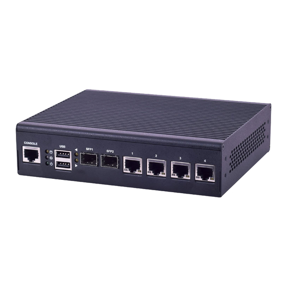
Page 15: Front I/Os
Front I/Os Console 1 x RJ-45 console port 1 x Power/status/storage LED set 2 x USB 2.0 Type-A ports 2 x SFP ports 4 x RJ-45 GbE LAN ports... -
Page 16: Rear I/Os
Rear I/Os Reset 1 x Reset button Power switch 1 x Power On/Off switch DC Power 1 x DC Jack with lock... -
Page 17: Chapter 3: Board Layout
Chapter 3: Board Layout Jumpers and Connectors on the Motherboard SFP3-4 USB1 LAN3-6 COM1 GPIO1 JBAT1 PS4P1 SATA6G_1 CON1 COMB2 SPIROM1 DCIN1... -
Page 18: Jumper Setting And Connector Pin-Out
Jumper Setting and Connector Pin-out J4: set the Reset Mode as Hardware (HW) Reset or Software (SW) Reset. (form : 1X3 2.54mm 3P DIP ). Default “short pins” are 2-3 as Software Reset HW Reset Switch input (default 1-2) SW Reset JBAT1: CMOS Clear. - Page 19 COM1: RJ45 Console port for serial console redirection purpose Description Description LNRTSA# LNDTRA# LNSINA LNSOUTA LNDSRA# LNCTSA# LPC1: 2x10-pin low pin count at 2.0mm Pin header DIP Description Description CLK_33M_P80 LPC_AD1 PLTRST_PORT80_N LPC_AD0 LPC_FRAME_N P3V3 LPC_AD3 Key ping LPC_AD2 GPIO1: 2x10-pin GPIO (General Purpose Input Output) at 2.0mm Pin header DIP Description Description SIO_GP20...
- Page 20 COMB2: internal COM pin header COMB2 Description Description NDCD2- NDSR2- NSIN2 NRTS2- NSOUT2 NCTS2- NDTR2- NRI2- COMGND2 SPIROM1: 2x10-pin SPIROM at 2.0mm Pin header SMD for debug purpose Description Description SPI_HOLD0_L PMU_AVN_SPI_R_CS0 V_3P3_SPI PMU_AVN_SPI_MISO PMU_AVN_SPI_R_CLK PMU_AVN_SPI_R_MOSI CON1: Nano SIM card slot...
- Page 21 Description PAD1 PAD2 LAN3~6: RJ45 Ethernet connectors without transformer Description MDX0+ MDX0- MDX1+ MDX2+ MDX2- MDX1- MDX3+ MDX3-...
- Page 22 SATA6G_1: SATA 7-pin signal connector Description Description PS4S1: SATA 4-pin power connector Description...
- Page 23 CN6: Mini-PCIe Socket Description Description PMU_WAKE# VCC3 1.5V NC_RSV1 SMB_CLK NC_RSV2 MINI_PCIE_TXN0 1.5V SMB_DATA MINI_CLKREQ_N1 MINI_PCIE_TXP0 NC_UIM_PWR NC_UIM_DATA USB_IO3_DN MINIPCIE_REFCLKN NC_UIM_CLK USB_IO3_DP MINIPCIE_REFCLKP VCC3 NC_UIM_RST VCC3 NC_UIM_VPP NC_LED_WWAN# NC_RSV3 NC_LED_WLAN# NC_RSV4 NC_RSV9 RF_KILL_N2_R NC_LED_WPAN# NC_RSV10 PLTRST_MINIPCIE_N 1.5V MINI_PCIE_RXN0 NC_RSV11 P3VSB MINI_PCIE_RXP0 NC_RSV12 VCC3...
- Page 24 CN1: Mini-PCIe socket functions as mSATA Description Description P3V3 SMB_HOST_3V3_CLK mSATA_TX0_DN SMB_HOST_3V3_DAT mSATA_TX0_DP P3V3 P3V3 mSATA_LED PLTRST_mSATA_N mSATA_RX0_DP P3V3 mSATA_RX0_DN P3V3...
- Page 25 SFP1~2: SFP GbE ports Description TX Fault TX Disable MOD_DEF2/SDA (DATA) MOD_DEF1/SCL (CLK) MOD_DEF0 RX_LOS VCC_R1 (PWR2) VCC_T1 (PWR1)
-
Page 26: Chapter 4: Hardware Setup
Please wear ESD protected gloves before conducting the following steps. Do NOT pile any object onto the system. 1. Power off FW-7526 completely and remove all power connections. 2. Remove the screws from the bottom and two sides, as circled in the figures below. -
Page 27: Installing The System Memory
3. Slide the compartment as the arrows of directions below to access the inside of the system. Installing the System Memory The motherboard supports DDR3 1333MHz (non-ECC) SO-DIMM Single channel up to 16GB. Please follow the steps below to install the DIMM memory modules. 1. -
Page 28: Installing Msata And Mini-Pcie Modules
Installing mSATA and Mini-PCIe Modules The motherboard provides a mSATA mini socket and a mini-PCIe socket. Please follow the procedures below for installation. 1. Locate the mSATA mini and mini-PCIe sockets. 2. Insert modules as shown in the image below. 3. -
Page 29: Chapter 5: Bios Setup
Chapter 5: BIOS Setup To enter the BIOS setup utility, simply follow the steps below: 1. Boot up the system. 2. Press <Delete> during the boot-up. Your system should be running POST (Power-On-Self-Test) upon booting up. 3. Then you will be directed to the BIOS main screen. 4. -
Page 30: Main
Main The [Main] is the first setup screen when you enter BIOS. The [Main] displays general system and BIOS information and you may configure “System Date”, and “System Time”. BIOS Information Core Version: displays core version information Project Version: displays version information Compliancy: displays compliancy information Build Date and Time: displays the date and time the BIOS was built. -
Page 31: Advanced
Advanced Use [<--] / [-->] to select [Advanced] setup screen. Under this screen, you may use [↑] [↓] to select an item you wish to configure. PXE Function You may choose to enable or disable PXE (Preboot Execution Environment) function. -
Page 32: W836270Hg Super Io Configuration
Press Enter to enable or disable the PXE function. W836270HG Super IO Configuration You may press Enter to access system super I/O chip parameters. -
Page 33: Serial Port 1/2 Configuration
Serial Port 1/2 Configuration You may press Enter to configure serial port 1/2 parameters. - Page 34 Once you have entered Serial Port 1 Configuration, you may enable or disable this serial port.
- Page 35 Once you have entered Serial Port 2 Configuration, you may enable or disable this serial port.
-
Page 36: W836270Hg Hw Monitor
W836270HG HW Monitor This option allows you to view hardware health status. you may use [↑] [↓] to select ‘‘Hardware Monitor’’ and press ‘‘Enter’’. -
Page 37: Serial Port Console Redirection
Serial Port Console Redirection This option allows you to configure parameters about serial port console redirection. Press “Enter” to access the submenu. select “Enabled” or “Disable” for an available COM port to set up Console Redirection: the console redirection. Then you may use [↑] [↓] to enter ‘‘Console Redirection Settings’’. Notably, the ‘‘Console Redirection Settings’’... - Page 38 the emulation configuration. Select “VT100”, “VT100+”, “VT-UTF8” or Terminal Type: “ANSI”. VT100: ASCII character set VT100+: extends VT100 to support color function keys VT-UTF8: uses UTF8 encoding to map Unicode characters onto 1 or more ANSI: Extended ASCII character set select “9600”, “19200”, “38400”, “57600”, or “115200”...
- Page 39 select the value for data bits. In this case, “7” or “8”. Data Bits: a parity bit can be sent with the data bits to detect some transmission errors. Parity Bits: Select “None”, “Even”, “Odd”, “Mark” or “Space”.
- Page 40 : stop bits indicate the end of a serial data packet. The standard is 1 stop bit. Stop Bits Communication with slow devices may require more than 1. flow control can prevent data loss from buffer overflow. When sending data, if Flow Control: the receiving buffers are full, a “stop”...
- Page 41 this option enables/disables VT-UTF8 combination key VT-UTF8 Combo Key Support: support for ANSI/VT100 terminals. : on this mode, when “Enabled”, only text will be sent. This is to capture Recorder Mode terminal data.
- Page 42 select “Enable” or “Disable” for extended terminal resolution. Resolution 100 x 31: select “80x24” or “80x25”. The default for this case Legacy OS Redirection Resolution: is “80x24”.
- Page 43 select Function Key and Key Pad on Putty. You may select “VT100”, Putty KeyPad: “LINUX”, “XTERMR6”, “SCO”, “ESCN”, or “VT400”. The settings specify if BootLoader is selected than Legacy Redirection After BIOS POST: console redirection is disabled before booting to Legacy OS. Default value is “Always Enable” which means Legacy OS console redirection is always enabled after BIOS.
-
Page 44: Generation 2 Lan Bypass Configurations
Generation 2 LAN Bypass Configurations This option allows you to configure Generation 2 LAN bypass parameters. enable or disable LAN port 5 and 6 runtime bypass LAN5-6 Runtime Bypass:... - Page 45 enable or disable LAN port 5 and 6 system-off bypass LAN5-6 System Off Bypass:...
-
Page 46: Trusted Computing
Trusted Computing This option allows you to configure Trusted Computing settings. - Page 47 enable or disable BIOS support for security device. The Security Device Support: operating system will not show security device. TCG EFI protocol and INT1A interface will not be available.
-
Page 48: Usb Configuration
USB Configuration This option allows you to configure USB device Settings. displays information about USB module version USB Module Version: displays USB devices USB Devices: this function enables or disables legacy USB support. Auto option Legacy USB Support: disables legacy support if no USB devices are connected. Disable option will keep USB devices available only for EFI applications. - Page 49 enables or disables EHCI Hand-off function. This is a workaround for EHCI Hand-off: operating systems without EHCI hand-off support. The EHCI ownership change should be claimed by EHCI driver. this option allows you to enable or disable USB USB Mass Storage Driver Support: mass storage driver.
- Page 50 set USB time-out value (1, 5, 10 or 20 seconds) for Control, Bulk USB transfer time-out: and Interrupt transfers. set USB mass storage device Start Unit command time-out (10, 20, Device reset time-out: 30 or 40 seconds).
- Page 51 set the maximum time the device will take before it properly Device power-up delay: reports itself to the Host Controller. “Auto” uses default value. For example, it is 100ms as a root port.
-
Page 52: Intelrcsetup
IntelRCSetup Use [<--] / [-->] to select [IntelRCSetup] setup screen. Under this screen, you may use [↑] [↓] to select ‘‘Processor Configuration’’, ‘‘North Bridge’’ or ‘‘South Bridge’’ to configure the parameters. Processor Configuration Press Enter to access options about processor settings. - Page 53 this option allows users to enable or disable TM1. TM1 and GV3 must be enabled in TM1: order to support TM2. (TM: Thermal Monitor) an Intel hardware-based protection against malicious code. It will Execute Disable Bit: detect the memory in which a code can be executed or not. When enabled, it will prevent certain classes of malicious buffer overflow attacks when combined with a supporting OS.
-
Page 54: North Bridge Chipset Configuration
set the number of cores to enable in the SoC package. You may set “All”, Active Processor: “4”, or “2”. The default is “All”. North Bridge Chipset Configuration Memory Information Total Memory: displays total memory displays memory frequency Memory Frequency:... -
Page 55: South Bridge Chipset Configuration
South Bridge Chipset Configuration Once entered South Bridge setting, you may configure restore AC Power Loss states and SATA parameters. restore on AC power loss options. You may select “Auto”, Restore On Power Loss: “Power On” or “Power Off”. -
Page 56: Sata Configuration
SATA Configuration Press Enter to access items for SATA devices and settings. enable or disable SATA controller if supported by current CPU SKU SATA 3 Controller:... - Page 57 the selection to determine the SATA mode for your storage devices. You may SATA Mode: select “IDE” or “AHCI” mode. enable or disable the function of overwriting SIR (SATA Index Overwrite SIR Values: Register) values.
- Page 58 enable or disable the SATA device of this SATA port SATA 3 Port 0: if enabled for any of ports, Staggered Spin Up will be performed and only the drives Spin Up: which have this option enabled will spin up at boot. Otherwise all drives spin up at boot.
- Page 59 designates this port as hot pluggable Hot Plug: enable or disable external SATA device External Device:...
- Page 60 enable or disable mechanical switch function for connected SATA Mechanical Switch: device...
-
Page 61: Security
Security Use [<--] / [-->] to select [Security] setup screen. Under this screen, you may use [↑] [↓] to select an item you want to configure. set administrator password. Once set, then this only limits Administrator Password: access to Setup and is only asked for when entering Setup. set user password. -
Page 62: Boot
Boot Use [<--] / [-->] to select [Boot] setup screen. Under this screen, you may use [↑] [↓] to select an item you want to configure. set the number of seconds to wait for setup activation key. 65535 Setup Prompt Timeout: (0xFFFF) means indefinite waiting. -
Page 63: Save & Exit
Save & Exit Use [<--] / [-->] to select [Save & Exit] setup screen. Under this screen, you may use [↑] [↓] to select an item you want to configure. exit system setup after saving the configuration changes Save Changes and Exit: exit system setup without saving the configuration changes Discard Changes and Exit: restore to factory default setting... -
Page 64: Appendix A: Programming Watchdog Timer
Appendix A: Programming Watchdog Timer A watchdog timer is a piece of hardware that can be used to automatically detect system anomalies and reset the processor in case there are any problems. Generally speaking, a watchdog timer is based on a counter that counts down from an initial value to zero. The software selects the counter’s initial value and periodically restarts it. -
Page 65: Appendix B: Setting Up Console Redirection
Appendix B: Setting up Console Redirection Console redirection lets you monitor and configure a system from a remote terminal computer by re-directing keyboard input and text output through the serial port. These following steps illustrate how to use this feature. The BIOS of the system allows the redirection of console I/O to a serial port. -
Page 66: Appendix C: Programming Generation 3 Lan Bypass
2. Independent bypass status control for each pair up to a total of 4 pairs 3. Lanner Bypass Modules can bypass systems Ethernet ports on a host system during three instances: Just-on (Just-on is the brief moment when the internal power supply turns on and booting process starts), System off, or upon software request (during run-time). - Page 67 Lanner LAN Bypass Watchdog User Manual under the Accessories folder. Fro a description of the physical LAN ports equipped with this function, refer to Front Panel Features in Chapter1 Introduction.
-
Page 68: Appendix D: Programming The Lcm
• Parallel Text-based LCM: The LCM connects to the motherboard’s parallel port. The LCD screen can display 2 lines, 16 (or 20) characters per line. • USB and Serial Text or Graphic-based LCM: Our next generation LCM. Lanner engineers design a common source code to be deployed on these two differently interfaced LCM modules. - Page 69 Display Off turning off the LCM display Cursor Off/On NOT showing/showing the cursor on the LCM display Blinking off/On turning off/on the cursor blinking Writing “Lanner@Taiwan” displaying the specific sentences Reading “Lanner@Taiwan” reading the specific sentence CGram Test displaying the user-stored characters...
- Page 70 -LCM1 — Writing “Lanner@Taiwan” in line1. — To execute, please type: #./plcm_test -LCM1 -LCM2 — Writing “2013-11-05” in line 2. — To execute, please type: #./plcm_test -LCM2 Keypad — Get the keypad input: the 1st button is read in as Left, the 2nd button is read in as Up, the 3rd button is read in as Right, and the 4th button is read in as Down.
- Page 71 Virtualization Implemented by Parallel Port Pass Through By the utilization of the parallel port pass through, the Parallel Text-based LCM implements the following three kinds of virtualization in the Guest OS. - QEMU/KVM - Xen - VMWare Player Here, we take the Fedora 20 x86_64 operation system for instance to explain 3 virtualization respectively for parallel port pass through.
- Page 72 Setting --> VMWare Player’s setting page to select /dev/parport0 as parallel port device. (3) Open a terminal in the Guest OS and then issue the following commands to install Linux Kernel drivers. # modprobe parport # modprobe parport_pc # modprobe ppdev 4) Check that whether the /dev/parport0 exists or not.
-
Page 73: Appendix E: Terms And Conditions
Appendix E: Terms and Conditions Warranty Policy 1. All products are under warranty against defects in materials and workmanship for a period of one year from the date of purchase. 2. The buyer will bear the return freight charges for goods returned for repair within the warranty period;...
Need help?
Do you have a question about the FW-7526 and is the answer not in the manual?
Questions and answers