
Related Manuals for Cisco FM4200


Summary of Contents for Cisco FM4200
- Page 1 Cisco Ultra-Reliable Wireless Backhaul FM4200 Fiber Installation and Configuration Manual (Formerly Fluidmesh) Model FM4200F | Edition 1.14 | Firmware 8.5.0...
- Page 2 Copyright © Cisco and the Cisco logo are trademarks or registered trademarks of Cisco and/or its affiliates in the U.S. and other countries. To view a list of Cisco trademarks, go to this URL: www.cisco.com/go/trademarks. Third-party trademarks mentioned are the property of their respective owners. The use of the word 'partner' does not imply a partnership relationship between Cisco and any other company.
-
Page 3: Table Of Contents
5.1.1. Installing The Cisco FM4200 Fiber ..........30 Environmental Rating And Unit Roles ..........30 Installation Hardware ............... 30 5.1.2. Cisco FM4200 Fiber Status And Link LEDs ........30 Unit And Link Quality Status ............30 Boot Sequence ................31 5.1.3. - Page 4 Device Firmware Reboot ..............33 Resetting The Unit To Factory Settings ..........34 5.1.5. Suitability For Outdoor Installation ..........34 5.2. Connecting The Cisco Cisco FM4200 Fiber To A Network And Antennas ....................35 5.2.1. Terminal Assignments For Power And Data Connectors ....35 M12 A-Coded .................
- Page 5 7.7.5. The Device Status View ............. 150 The Device Status Window ............150 7.7.6. Saving And Restoring The Unit Settings ........152 7.7.7. Resetting The Unit To Factory Defaults ........154 © 2021 Cisco and/or its affiliates. All rights reserved. Page 5 of 189...
- Page 6 14.11. Limitation Of Liability ............... 186 14.12. Exclusion Of Liability For Emergency Services ........187 14.13. Export Control ................187 14.14. General ..................188 15. Contact Us ....................189 © 2021 Cisco and/or its affiliates. All rights reserved. Page 6 of 189...
-
Page 7: Hazardous Condition Warnings
HAZARDOUS CONDITION WARNINGS 1. HAZARDOUS CONDITION WARNINGS Like all other global technology vendors, Cisco is required to complywith all local health and government regulations in the location;s in whichwe operate. This includes meeting radio frequency (RF) exposure limitsfor our products. -
Page 8: Water Ingress Hazard
HAZARDOUS CONDITION WARNINGS 1.1. Water ingress hazard CAUTION In all circumstances where the Cisco FM4200 Fiber will be installed in an outdoor location, it is compulsory to mount the Cisco FM4200 Fiber inside an FM-SHIELD auxiliary mounting kit. The FM-SHIELD auxiliary mounting kit is a proprietary... -
Page 9: Radio-Frequency Transmission Hazard
RF exposure. Make sure that all RF feeds are securely connected to an appropriate antenna. Never activate any RF-capable device that is not connected to an antenna. © 2021 Cisco and/or its affiliates. All rights reserved. Page 9 of 189... -
Page 10: Optical Radiation Hazard
For additional guidance regarding the safe use of laser-based and LED-based fiber-optic technology, refer to ANSI Z136.2 (Safe Use of Optical Fiber Communication Systems Utilizing Laser Diode and LED Sources). IMPORTANT The Cisco FM4200 Fiber is not shipped from the factory with fiber-optic transceivers installed unless fiber-optic transceivers were specified as part of the purchase order. -
Page 11: Hot Surfaces Hazard
The outer surfaces of transceiver and gateway unit enclosures may become hot during normal operation. During normal operation, do not touch or handle the unit enclosure without personal protective equipment. © 2021 Cisco and/or its affiliates. All rights reserved. Page 11 of 189... -
Page 12: Reporting Mistakes And Recommending Improvements
If you find any mistakes, or if you know of a way to improve the procedures that are given, please let us know by E-mailing your suggestions to documentation@cisco.com. © 2021 Cisco and/or its affiliates. All rights reserved. Page 12 of 189... -
Page 13: Getting Started
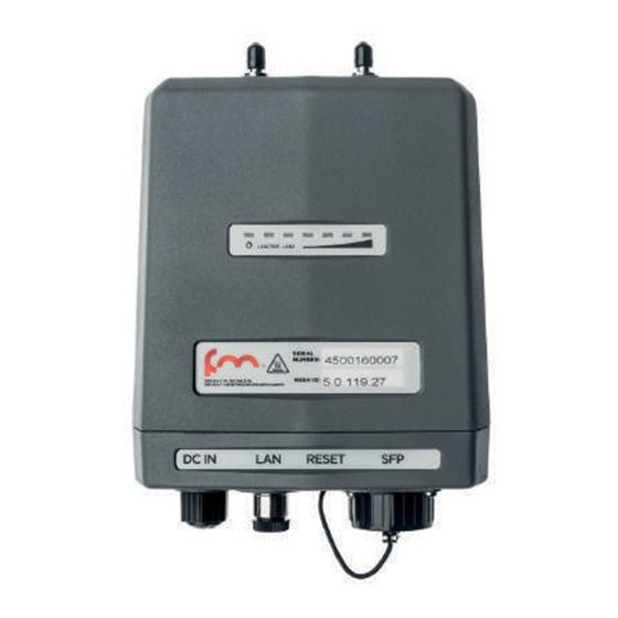
The Cisco FM4200 Fiber radio transceiver Introduction The Cisco FM4200 Fiber (model FM4200F) is designed to operate in the sub-6 GHz range as a static-mount wireless data link. In non-technical terms, this means it is designed to function as an intermediate radio link between a core wired and/or fiber-optic data network and a sub-network. -
Page 14: Unit Function And Throughput Speed
Cisco components is being upgraded,the Prodigy 1.0 protocol with limited functionality can be selected to guarantee compatibility. Prodigy uses a traffic optimization algorithm that allows every Cisco radio to assign a specific priority level to every forwarded data packet. Unit configuration The unit is compatible with Cisco RACER™. -
Page 15: Environmental Rating
For detailed product specifications, refer to the product data sheet for the Cisco FM4200 Fiber. Transceiver and gateway unit power consumption In service, Cisco transceiver units and gateway units consume electrical power at the rates given in the table below. IMPORTANT... -
Page 16: Cisco Architecture
3.2. Cisco architecture 3.2.1. Overview Wireless network architectures Depending on the network design and the type of components used, the Cisco FM4200 Fiber can be used to create wireless network architectures, including: • Point-to-point (P2P) links. • Point-to-multipoint (PTMP) sectors. -
Page 17: Cisco Technologies
Prodigy is Cisco's proprietary implementation of the Multi-Protocol- Label-Switching (MPLS) standard. IMPORTANT A Cisco device only features Prodigy selection if the installed Prodigy engine includes the selection feature. Cisco devices that are designed to operate exclusively in Bridge Mode (in other words, point-to-point configuration) do not feature Prodigy. -
Page 18: Fm Racer
Prodigy 1.0 and Prodigy 2.0 are not compatible with each other. Do not implement the two protocol versions within the same network. If you are expanding an existing network using new Cisco hardware components, make sure that all components are compatible with each other by: 1. -
Page 19: Mesh Network Architecture
In a reliable mesh network with an acceptable amount of redundancy, every stream of data packets may reach the base station through any of a variety of paths. The Cisco FM4200 Fiber is designed to act as an 'intelligent router' that is able to forward packets coming from other Cisco components in real time, based on an optimal, software- determined path. -
Page 20: Point-To-Multipoint Architecture With Fluidmax
(Figure 3 (page 21)) with improved features and capabilities that allow the technology to meet or exceed the needs of the security and industrial automation industries. © 2021 Cisco and/or its affiliates. All rights reserved. Page 20 of 189... - Page 21 Cisco radio transceiver unitsthat are part of the same network. Using FluidMAX technology, a Cisco unit can be used as the center point of a star topology in a point-to-multipoint network arrangement using sector antennas, or using antenna splitters connected to more than one directional antenna.
-
Page 22: Cisco Network Addressing
3.3. Cisco Network Addressing 3.3.1. Bridge IP addressing If needed, the Cisco FM4200 Fiber can be operated in Bridge mode. This creates a single point-to-point connection between two network segments. A simplified example of a Bridge mode connection is shown in... -
Page 23: Operating The Unit In Mesh Point Mode Or Mesh End Mode
Figure 5. Cisco Network Addressing Operating the unit in Mesh Point mode or Mesh End mode If the Cisco FM4200 Fiber radio transceiver unit is installed as part of a mesh network architecture, it can be set to operate in either of two operating modes: ©... -
Page 24: Network Addressing
Cisco radio transceivers Cisco data link layer (layer 2) addressing allows you to configure each Cisco FM4200 Fiber transceiver unit, and each IP device connected to the unit, according to the IP address class used in the private LAN to which the Mesh End unit is connected. -
Page 25: Connecting And Configuring An Ethernet Edge Device
Connecting and configuring an Ethernet edge device Ethernet edge devices such as IP cameras and Wi-Fi access points can be connected to the Ethernet ports of the Cisco FM4200 Fiber. Such edge devices must be configured using the IP subnet scheme defined for the broadcast domain. -
Page 26: Installing The Radio
Aim and adjust the radio correctly. You can aim the unit in the horizontal plane only. Tighten the tie-wraps or hose clamps until the radio assembly is secure. © 2021 Cisco and/or its affiliates. All rights reserved. Page 26 of 189... -
Page 27: Installation On A Din Rail
Screw the DIN mounting plate to the main body of the transceiver using the supplied machine screws (below). © 2021 Cisco and/or its affiliates. All rights reserved. Page 27 of 189... -
Page 28: Installation Using The Sliding Bracket
DIN mounting plate slots onto the DIN rail. 4.3. Installation using the sliding bracket All FM3200 Endo, FM3500 Endo, FM4200-series, FM4500-series and FM4800 Fiber transceivers can take advantage of quick-release installation if they are installed using the sliding bracket (part number FM- BRKT-SLIDING). - Page 29 Note that the antenna terminals of the radio unit must face up (below). © 2021 Cisco and/or its affiliates. All rights reserved. Page 29 of 189...
-
Page 30: Hardware Installation
Installation hardware Metal clamps are supplied as part of the installation package, to allow mounting of the unit on utility poles. Refer to the Cisco FM4200 Fiber installation instructions for details. 5.1.2. Cisco FM4200 Fiber Status and link LEDs... -
Page 31: Boot Sequence
5.1.3. Supplying power to the Cisco FM4200 Fiber CAUTION When connecting the Cisco FM4200 Fiber to a power supply, be sure to follow the instructions in this section at all times. Failure to follow these instructions may result in irreparable damage to the unit and/or other connected hardware, and will also invalidate the product warranty. -
Page 32: Connecting Power To The Cisco Fm4200 Fiber
Hardware installation The Cisco FM4200 Fiber can be provided with power using the following methods: • A standard IEEE 802.3af Power-over-Ethernet (PoE) connection (for example, from a compatible network switch). • A compatible 48 Vdc passive PoE injector conforming to either IEEE 802.3af... -
Page 33: Rebooting The Firmware And Resetting The Unit To Factory Defaults
5.1.4. Rebooting the firmware and resetting the unit to factory defaults The Cisco FM4200 Fiber hardware can be rebooted and reset to factory default condition using the procedures in this section. IMPORTANT The following procedure shows how to do a 'hard' (device firmware) reboot. -
Page 34: Resetting The Unit To Factory Settings
1. To do the reset using the offline Configurator interface, refer to “Resetting the unit to factory defaults” (page 154). 2. To do the reset using FM Racer, refer to the Cisco Networks FM Racer User Manual. 3. To do the reset by physically accessing the unit, follow the procedure below. -
Page 35: Antennas
5.2.1. Terminal assignments for power and data connectors IMPORTANT Always use outdoor-rated, RF-shielded Ethernet cables when connecting the Power and LAN ports of a Cisco hardware device to external hardware. M12 A-coded This section describes the terminal assignments for M12 A-coded connectors equipped with five pins (power only) and with eight pins (power and data). -
Page 36: M12 A-Coded Eight-Pin (Pre-September 2016 Only)
• Terminal 2 of M12A (Brown wire with white tracer) to terminal 7 of RJ45. • Terminal 3 of M12A (Brown wire) to terminal 8 of RJ45. • Terminal 4 of M12A (Orange wire) to terminal 2 of RJ45. © 2021 Cisco and/or its affiliates. All rights reserved. Page 36 of 189... -
Page 37: M12 X-Coded
• Terminal 8 of M12A (Green wire) to terminal 4 of M12X. M12 X-coded M12 X-coded connectors are used on all Cisco 4200-seriesand Cisco 4500-series units manufactured after September 2016. When splicing a male M12 X-coded connector to one end of an Ethernet... -
Page 38: Xco / Sfp / Sfp
• Terminal 8 of M12X (Blue wire) to terminal 4 of RJ45. XCO / SFP / SFP+ WARNING If a Cisco device is fitted with an XCO-type fiber-optic module, it is a Class 1 laser product. It makes use of fiber-optic technology, including laser-emitting components. -
Page 39: Connecting Fiber-Optic Connectors To Sfp Modules
If you experience difficulty in sourcing or ordering fiber- optic parts or accessories, please contact your local Cisco Networks representative for assistance. The terminal assignments for male SFP connectors are as follows:... - Page 40 SFP module until you hear a positive Click sound. Slide the round threaded tube forward along the fiber-optic cable. Screw the tube onto the port connector by hand (below). © 2021 Cisco and/or its affiliates. All rights reserved. Page 40 of 189...
-
Page 41: Connecting A Dc In Power Source To The Unit
“Connecting LAN cables to the unit” (page 42). When the Cisco FM4200 Fiber is mounted in its final location, connect the unit to a 48V DC IN power supply by doing the following steps: Only use a power cable that terminates in an M12A connector to connect the power source to the unit. -
Page 42: Connecting Lan Cables To The Unit
48V DC IN power supply to the unit as shown in “Connecting a DC IN power source to the unit” (page 41). When the Cisco FM4200 Fiber is mounted in its final location, connect the unit to LAN connection(s) and/or a PoE power supply by doing the following steps: Only use a shielded CAT5/6 cable that terminates in an M12X connector to connect any LAN cable to the unit. - Page 43 5. Insert the M12X connector leading from the local LAN hardware into the port labelled LAN. 6. Screw the threaded sleeve of the female connector onto the male connector. Tighten the connection by hand. © 2021 Cisco and/or its affiliates. All rights reserved. Page 43 of 189...
-
Page 44: Connecting An Xco-Standard Duplex Fiber-Optic Cable To The Unit
5.2.4. Connecting an XCO-standard duplex fiber-optic cable to the unit WARNING If a Cisco FM4200 Fiber transceiver is fitted with an XCO / SFP fiber-optic module, it is a Class 1 laser product. It makes use of fiber-optic technology, including laser-emitting components. Do not look directly at the input/output end of the unit's SFP connector, or at the input/output end of any fiber-optic cable. - Page 45 • The mylar tab-type module has a tab that is pulled to remove the module (below). • The actuator button-type module has a button that is pushed to remove the module (below). © 2021 Cisco and/or its affiliates. All rights reserved. Page 45 of 189...
- Page 46 SFP modules are static-sensitive devices. Always use an ESD wrist strap or similar individual grounding device when handling an SFP module. To install an XCO-type SFP module in the Cisco FM4200 Fiber, do the following steps: Wear an ESD-preventive wrist or ankle strap, and follow its instructions for use.
- Page 47 Push gently but firmly on the outer face of the module. If the module is correctly aligned, you will hear a click as the slide pin at the bottom of the module snaps into place. To remove an XCO-type SFP module from the Cisco FM4200 Fiber, do the following steps: CAUTION Do not remove or insert SFP modules any more often than absolutely necessary.
-
Page 48: Connecting The Antennas To The Cisco Fm4200 Fiber
5. Waterproof the connection as directed by the manufacturer of the SFP module. 5.2.5. Connecting the antennas to the Cisco FM4200 Fiber QMA antenna connections IMPORTANT The FM4200 Fiber is ingress-protection rated to standards specified by EN 50155 and EN 45545. - Page 49 Hardware installation Radio antennas are connected to the Cisco FM4200 Fiber using quick- disconnect sub-miniature version A (QMA) connectors. WARNING Before activating the unit, make sure that all RF feeds are securely connected to an appropriate antenna. Never activate any transceiver unit that is not connected to an antenna.
- Page 50 7. Slide the lengths of Nylon heat-shrinkable tubing over the tightened QMA connectors. 8. Use a heat gun to shrink the tubing onto the connectors. © 2021 Cisco and/or its affiliates. All rights reserved. Page 50 of 189...
-
Page 51: Using The Cisco Partner Portal
Using the Cisco Partner Portal 6. Using the Cisco Partner Portal The Cisco Partner Portal is the main web-based portal through whichthe following activities are done: Participating in Cisco E-learning Using and sharing plug-in license codes for Cisco devices Using the RACER™ radio configuration interface 4. -
Page 52: Enabling Two-Factor Authentication For Security
Safari later 6.2. Enabling Two-Factor Authentication for security To enhance cyber-security on the Partner Portal, Cisco uses two- factor authentication (2FA). 2FA works by providing an extra security layer that works independently of your Partner Portal login password. With 2FA activated, you will be asked to provide a secure one-time password (OTP) for each login. -
Page 53: Administering Plug-In License Codes
The Partner Portal Plug-ins page can be used to do the following tasks: • Convert plug-in License codes to Activation codes • Deactivate active plug-in License codes © 2021 Cisco and/or its affiliates. All rights reserved. Page 53 of 189... -
Page 54: Using The Racer™ Radio Configuration Interface
Documentation section of the Partner Portal. To find documentation relating to your Cisco device, do the following steps: Log in to the Cisco Partners Portal using your login credentials. -
Page 55: Device Configuration Using The Configurator Interface
Device configuration using the configurator interface 7. Device configuration using the configurator interface Cisco radio devices that are capable of operating as part of a mesh network, including the Cisco FM4200 Fiber, are shipped from the factory in Mesh Point mode. - Page 56 • Ethernet speed (Selects the correct data exchange speed for each Ethernet port.) • CISCO WI-FI tab (Allows you to set up a second, segregated Wi-Fi interface that allows technicians access to the unit for configuration and maintenance purposes.)
-
Page 57: Software And Hardware Prerequisites
7.1. Software and hardware prerequisites To access the Configurator graphical user interface (GUI) and use the Configurator to program the Cisco FM4200 Fiber, you need the following: • A desktop, laptop or tablet computer equipped with: • Any current web browser. For a list of compatible web browsers, refer to the Supported web browsers table in “Using the Cisco Partner Portal”... -
Page 58: Local Access And Login For Initial Configuration
• IP address: 192.168.0.10 (or any other IP address belonging to subnet 192.168.0.0/255.255.255.0) • Netmask: 255.255.255.0 Launch the computer's web browser. Enter the IP address of the Cisco FM4200 Fiber in the browser's URL entry field. • If the Configurator interface is shown immediately, proceed Step 9 below. - Page 59 This is normal and expected. During the configuration process, it is safe to ignore these warnings. Click the ADVANCED link. • You will see the following window: © 2021 Cisco and/or its affiliates. All rights reserved. Page 59 of 189...
- Page 60 Enter the correct username and password. Press 'Enter'. If your browser shows a time-out or similar message, the computer may be trying to access the Cisco device througha proxy server. To resolve the issue, do the following steps: 1. Go to Control Panel > Internet Options > Connections >...
-
Page 61: Initial Configuration With The Unit In Provisioning Mode
142). 7.2.2. Initial configuration with the unit in Provisioning Mode The Cisco FM4200 Fiber cannot be operated without entering some basic configuration settings. These settings allow the unit to connect to a local network and communicate with the network hardware. - Page 62 • If you want to change the connection settings, but keep the current configuration, change the settings as shown in “General settings” (page 70). If the Cisco FM4200 Fiber is in Provisioning Mode: • The RACER™ dialog will be shown (Figure 17 (page 63)).
- Page 63 NOTE DHCP is disabled when the unit leaves Provisioning Mode. Make sure that the Cisco FM4200 Fiber is connected to a local network that supports DHCP. If the unit connects successfully to the internet and to the Partners Portal, the RACER™ Cloud connection info Status will be...
- Page 64 Configure the unit using either of the following methods: • To do a centralized (online) configuration of the unit using the FM Racer interface, refer to the Cisco Networks FM Racer User Manual. • To do a local (offline) configuration using the Configurator interface, refer to “Device configuration using the configurator interface”...
- Page 65 Figure 20. RACER™ Cloud connection info status (Disconnected) Configure the unit by doing the following steps: Click the Reset to Provisioning button at the bottom of the DHCP fall-back configuration section. © 2021 Cisco and/or its affiliates. All rights reserved. Page 65 of 189...
- Page 66 For a quick overview of the initial configuration process, refer to the flowchart below. NOTE Each individual Cisco radio transceiver unit has a factory-set mesh identification number that takes the form 5.w.x.y. If the unit's IP address is set to 169.254.x.y/24 as in Case 2 below, the values x and y represent parts x and y of the unit's mesh identification number.
-
Page 67: Switching Between Offline And Online Modes
To switch between Offline and Online modes, do the steps that follow: Log in to the Configurator interface as shown in “Accessing the Cisco FM4200 Fiber for device configuration” (page 57). • The Configurator landing page will be shown... -
Page 68: Uploading A Device Configuration File From Fm Racer
A FM Racer device configuration template contains a set of pre- configured parameters that can be customized and applied to a single Cisco device, or to a group of devices. © 2021 Cisco and/or its affiliates. All rights reserved. Page 68 of 189... - Page 69 • Alternatively, you can create a new, custom configuration template. For instructions on how to copy, modify or create a configuration template using the FM Racer interface, refer to the Cisco Networks FM RacerUser Manual. A configuration file that has been created using the FM Racer interface must be uploaded to the unit.
-
Page 70: General Settings
Click the -general mode link under GENERAL SETTINGS in the left-hand settings menu (below). Figure 23. Configurator GUI (General Mode) • The GENERAL MODE dialog will be shown (Figure 23 (page 70)). © 2021 Cisco and/or its affiliates. All rights reserved. Page 70 of 189... -
Page 71: Changing The Operational Mode
Changing the operational mode on a mesh network-capable unit The General Mode box (below) contains the operational mode controls. Cisco radio transceiver units that are capable of operating within a mesh radio network are shipped from the factory in Mesh End mode. -
Page 72: Changing The Prodigy Version
Changing the Prodigy version IMPORTANT Prodigy version selection is only available if the Cisco FM4200 Fiber is set to Mesh Point mode or Mesh End mode. If the unit is set to Bridge mode, the Prodigy Version selector will not be available. -
Page 73: Changing The Lan Parameters
Device configuration using the configurator interface Remember that all Cisco devices within a network must use the same Prodigy version. IMPORTANT Prodigy 2.0 is not compatible with Prodigy 1.0. Do not implement the two protocol versions within the same network. -
Page 74: Wireless Settings
7.4.2. Wireless settings Modifying the wireless settings IMPORTANT If the Cisco FM4200 Fiber was purchased in the USA or Canada, the Country selection is set to the country of purchase, and the Country: drop-down will be disabled. The WIRELESS RADIO window contains controls to change the following settings: •... - Page 75 Enter a defined network passphrase in the Shared Passphrase field. IMPORTANT If a shared passphrase is defined, the same passphrase must be used for all Cisco units inthe same network. The shared passphrase can be composed of any ASCII characters except the following: '`"\$= Specify the country in which the unit is installed by selecting the correct option from the Country drop-down menu.
-
Page 76: Important Considerations For Wireless Settings
(page 78). Point-to-Point and Point-to-Multipoint considerations If a Cisco radio transceiver unit's FluidMAX Auto scan setting is enabled, and the unit is assigned a Subordinate role within a point-to- multipoint network topology: • The Subordinate unit will mimic the frequency setting of the primary unit that shares its cluster ID. -
Page 77: Co-Location Considerations
IMPORTANT The following table shows theoretical values under ideal conditions. Actual throughput may vary depending on environmental and other conditions. © 2021 Cisco and/or its affiliates. All rights reserved. Page 77 of 189... -
Page 78: Dynamic Frequency Selection Considerations
IMPORTANT The dynamic frequency selection feature must be enabled using a software plug-in ( Cisco part number FM-UNII2). Contact your Cisco Networks representative for details. If it is essential that the unit is operated in the U-NII Mid or U-NII... -
Page 79: Antenna-Alignment Tools And Physical Statistics
• The Partner Portal will verify that there are no TDWR radar installations within 40 miles (64 Km) of the Cisco unit.If no TDWR radar installations are found, the plug-in willgrant permission for the unit to be set to frequencies withinthe 5.250 GHz-to-5.350 GHz band, and the 5.470 GHz-... - Page 80 Device configuration using the configurator interface The window shows a list of wireless links to other Cisco units that have been detected by the local unit, and the relative strength of each wireless link in decibel-milliwatts (dBm). To do an accurate alignment of a local antenna for a specific wireless link,...
-
Page 81: Spectral Analysis
The Spectrum Graph window contains a static graph readout and controls to detect radio-frequency interference that exists between local Cisco units transmitting and receiving in a specified frequency band.The window can be used make the most efficient choice of center frequency and channel width for radio links between units. - Page 82 To reset the window to default size, click the Reset Zoom button on the upper right-hand corner of the Spectrum Graph window. © 2021 Cisco and/or its affiliates. All rights reserved. Page 82 of 189...
-
Page 83: Network Control
IP addresses. If connectivity is lost between the unit and any of the saved IP addresses, an option can also be set to automatically reboot the Cisco FM4200 Fiber. As well as being a fail-safe mechanism to monitor network... - Page 84 To automatically reboot the unit if connectivity is lost between the unit and any IP address, do the following steps: 1. Check the Reboot: check-box. 2. Click the Save button. © 2021 Cisco and/or its affiliates. All rights reserved. Page 84 of 189...
-
Page 85: Fm-Quadro
FM-QUADRO for mesh network-capable devices IMPORTANT The FM-QUADRO tool is only available if the Cisco FM4200 Fiber is set to Mesh End mode or Bridge mode. If the unit is set to Mesh Point mode, the -FMQuadro™ menu option will not be available. -
Page 86: Plotting And Interpreting The Wireless Links
• A graphical view of the current network topology will be shown. A typical example is shown below. © 2021 Cisco and/or its affiliates. All rights reserved. Page 86 of 189... - Page 87 • The device type icon. Depending on device type, any of three icons may be seen: • The icon below will be shown if the device is a stationary non-Fluidity radio device: © 2021 Cisco and/or its affiliates. All rights reserved. Page 87 of 189...
- Page 88 Cisco Mesh ID number willbe shown. • If the network is a Fluidity network, mobile Cisco radio transceivers that are part of the network are shown as tooltips with colored borders. The tooltip representing a mobile Cisco radio is always shown below the tooltip of ©...
- Page 89 FM-QUADRO view. Network connectivity links between stationary radio transceivers are shown as lines: • A wired LAN link is shown as a solid black line (below). © 2021 Cisco and/or its affiliates. All rights reserved. Page 89 of 189...
-
Page 90: Viewing Live Data For A Radio Or Wireless Link
• For stationary radio transceivers, an information sidebar will be shown on the right side of the view (a typical sidebar is shown below). © 2021 Cisco and/or its affiliates. All rights reserved. Page 90 of 189... - Page 91 • If the device is a stationary radio, a list of IP addresses belonging to all non-Cisco edge devices currently connected to the device will be shown. © 2021 Cisco and/or its affiliates. All rights reserved. Page 91 of 189...
- Page 92 IP addresses, connected by a double-pointed line. • The main body of the widget contains live readings on uplink and downlink throughput, LER, PER, RSSI, MCS, and modulation rates. © 2021 Cisco and/or its affiliates. All rights reserved. Page 92 of 189...
-
Page 93: Viewing Live Rssi Data For A Wireless Link
• The solid lines on the upper part of the graph are RSSI readings for other stationary and mobile radios that are part of the network. © 2021 Cisco and/or its affiliates. All rights reserved. Page 93 of 189... -
Page 94: Manipulating The Fm-Quadro View
FM-QUADRO view. To move any icon or tooltip, do the steps that follow: Click the Edit Mode icon on the upper right part of the FM- QUADRO view (below). © 2021 Cisco and/or its affiliates. All rights reserved. Page 94 of 189... - Page 95 When you are finished editing, click the Save changes button to save your changes. Alternatively, click the Discard changes button to revert to your previous configuration. © 2021 Cisco and/or its affiliates. All rights reserved. Page 95 of 189...
-
Page 96: Showing Kpi Values For Wireless Links
Alternatively, click the Discard button to leave the dialog without saving any changes. • An information ribbon containing chosen performance indicators will be shown next to all wireless link lines (a typical example is shown below). © 2021 Cisco and/or its affiliates. All rights reserved. Page 96 of 189... -
Page 97: Showing Real-Time Color Codes For Radio Transceiver Key Performance Indicators
You can add an aerial image to the FM-QUADRO view. This allows you to superimpose the network map over a map of the actual terrain on which © 2021 Cisco and/or its affiliates. All rights reserved. Page 97 of 189... - Page 98 If needed, move the device icons and/or tooltips to suit the aerial image as shown in “Changing the relative position of device icons” (page 94). © 2021 Cisco and/or its affiliates. All rights reserved. Page 98 of 189...
-
Page 99: Adjusting The Transparency Of The Aerial Map View
To export a representation file for the current network, do the steps that follow: Click the Export as JSON icon on the upper right part of the FM- QUADRO view (below). © 2021 Cisco and/or its affiliates. All rights reserved. Page 99 of 189... -
Page 100: Advanced Tools
To use the Ping test tool, do the following steps: Determine which wireless link is to be tested between the Cisco unit and another unit in the wireless network. Get theIP address of the other unit. Enter the IP address of the other unit in the Ping (10 packets... -
Page 101: Using The Bandwidth Test Tool
To use the Bandwidth test tool, do the following steps: Determine what wireless link is to be tested between the Cisco unit and another unit in the wireless network. Get theIP address of the other unit. Enter the IP address of the other unit in the Bandwith test... -
Page 102: Using The Path Mtu Discovery Tool
To use the Path MTU discovery tool, do the following steps: Determine what wireless link is to be tested between the Cisco unit and another unit in the wireless network. Get theIP address of the other unit. Enter the IP address of the second unit in the Path MTU... -
Page 103: Advanced Settings
• The maximum distance over which the unit is capable of transmitting To open the Advanced Radio Settings dialog, click the -advanced radio settings link under ADVANCED SETTINGS in the left-hand settings menu (below). © 2021 Cisco and/or its affiliates. All rights reserved. Page 103 of 189... -
Page 104: Using The Fluidmax Management Setting
• AUTO: The FluidMAX engine is enabled, and the unit role is set automatically. Depending on various factors, the unit will automatically choose whether to transmit using the © 2021 Cisco and/or its affiliates. All rights reserved. Page 104 of 189... -
Page 105: Using The Max Tx Power Setting
Using the Max TX Power setting This setting controls the effective isotropic radiated power (EIRP) output of the unit. By default, EIRP is automatically regulated using Cisco's Transmission Power Control (TPC) algorithm. The algorithm tries to obtain an optimal link signal strength of approximately -55 dBm on both sides of ©... -
Page 106: Using The Select Antenna Gain Setting
IMPORTANT The Data Packet Encryption setting must be the same on all Cisco units that are part of the same network. © 2021 Cisco and/or its affiliates. All rights reserved. Page 106 of 189... -
Page 107: Using The Maximum Link Length Setting
Device configuration using the configurator interface In Cisco devices, AES is applied using a proprietary encoding algorithm, enabling industry-grade network security. IMPORTANT The AES feature must be enabled using a software plug-in (FM-AES). Contact your Cisco Networks representativefor details. To use the Data Packet Encryption setting, do the following steps: Click the Data Packet Encryption drop-down menu. -
Page 108: Sfp Settings
Device configuration using the configurator interface 7.6.2. SFP settings IMPORTANT The Cisco FM4200 Fiber is shipped from the factory with no fiber-optic transceiver installed. For the unit to have fiber-optic capability, the SFP port must be equipped with a separately-available XCO-type fiber-optic transceiver. -
Page 109: Pass Lists And Block Lists
7.6.4. Pass lists and Block lists IMPORTANT The Pass list or Block list feature is only available if the Cisco FM4200 Fiber is set to Mesh Point mode or Mesh End mode mode. If the unit is set to Bridge mode, the –pass list / block list menu option will not be available. - Page 110 Device configuration using the configurator interface A Pass list is a group of Cisco transceivers, described as a list of linked pairs. Within the list, each transceiver unit is considered a valid hop in the routing table. If a Pass list is created, all transceiver units that are not on the Pass list are excluded from packet routing.
- Page 111 • Cell A2 of the *.CSV file would contain the parameter 5.29.252.213, 5.2.22.136,0 • Cell A3 of the *.CSV file would contain the parameter 5.29.252.213,5.155.105.128,1 • Cell A4 of the *.CSV file would contain the parameter 5.155.105.128,5.29.252.213,1 © 2021 Cisco and/or its affiliates. All rights reserved. Page 111 of 189...
- Page 112 Click the –pass list / Block list link under ADVANCED SETTINGS in the left-hand settings menu. Figure 40. Configurator (Pass list / Block list dialog) © 2021 Cisco and/or its affiliates. All rights reserved. Page 112 of 189...
-
Page 113: Multicast
By default, if CCTV cameras and devices that operate in a similar fashion are linked to a Cisco transceiver unit operating in Mesh Point mode,the unit forwards all multicast traffic generated by the cameras to the closest Mesh End unit in the wireless network. - Page 114 224.1.1.0/24 indicates all multicast groups in the range 224.1.1.1 through 224.1.1.254. • The destination address consists of one or more Cisco unit ID numbers, in the form 5.a.b.c. These ID numbers belong to the physical Cisco device or devices to which the multicast traffic must be forwarded.
-
Page 115: Configuring Multicast Within A Layer-3 Network
Within a typical Layer-3 network, consider a scenario in which Multicast traffic must be routed in both directions between Fluidity-enabled, vehicle- mounted radio transceivers, and the global gateway unit that governs data traffic through the core network. © 2021 Cisco and/or its affiliates. All rights reserved. Page 115 of 189... -
Page 116: Snmp Configuration
If SNMP traps are enabled, you can specify the server address to which monitoring information must be sent. IMPORTANT The same SNMP configuration must be set for all Cisco units in the wireless network. detailed information... -
Page 117: Using Snmp V2C
SNMP mode drop-down, and click the v2c option. • The SNMP v2c settings dialog will be shown (Figure 45 (page 117)). Figure 45. SNMP dialog (v2c selected) © 2021 Cisco and/or its affiliates. All rights reserved. Page 117 of 189... -
Page 118: Using Snmp V3
Click the SNMP mode drop-down, and click the v3 option. • The SNMP v3 settings dialog will be shown (Figure 46 (page 119)). © 2021 Cisco and/or its affiliates. All rights reserved. Page 118 of 189... - Page 119 To change the current SNMP v3 password, enter a new password in the SNMP v3 password: field. The default password is cisco. To show the password as it is being typed, checkthe Show SNMP v3 password: check-box. Choose the correct authentication protocol from the SNMP v3 authentication proto: drop-down.
-
Page 120: Wireless Access Point Configuration
Save the SNMP settings by clicking the Save button. Alternatively, clear the settings by clicking the Reset button. 7.6.7. Wireless access point configuration All FM1200 Volo, Cisco 3200-series and Cisco 4200-series radio transceivers equipped with firmware version 6.5 and above have a built-in wireless access point (AP). - Page 121 Device configuration using the configurator interface To enable the wireless AP feature on the Cisco FM4200 Fiber, do the steps that follow: 1. Make sure the FM-AP software plug-in is installed on the radio unit. For instructions on how to install the FM-AP plug-in, refer to “Plug-in management procedures”...
- Page 122 4. If the wireless AP has been set to routed configuration and access to other Cisco radio units that are part of the same network is needed, facilitate access by adding routes to the relevant radio units as described in “Static routes”...
- Page 123 WLAN Passphrase entry field. 6. To show the WLAN passphrase in plain text as it is being entered, check the Show Passphrase check-box. © 2021 Cisco and/or its affiliates. All rights reserved. Page 123 of 189...
-
Page 124: Radius Configuration
• Wi-Fi capability. • A current version of Mozilla Firefox or Google Chrome. To connect wirelessly to the Cisco FM4200 Fiber for configuration and maintenance, do the following steps: 1. On your computer or other wireless interface device, use the Wi- Fi connection dialog to connect to the radio unit using the radio unit's WLAN SSID and WLAN passphrase. - Page 125 RADIUS networking protocol. Do not change these settings unless there is a specific need to do so. To change the RADIUS settings for the Cisco unit, do the following steps: Enable and configure network time protocol (NTP) as shown in “NTP Configuration”...
- Page 126 Enter the RADIUS access password in the Secret field. To read the password as it is typed, check the show check-box. © 2021 Cisco and/or its affiliates. All rights reserved. Page 126 of 189...
- Page 127 • GTC PEAP • MSCHAPV2 • MD5 • GTC 12. Save the RADIUS settings by clicking the Save button. Alternatively, clear the settings by clicking the Reset button. © 2021 Cisco and/or its affiliates. All rights reserved. Page 127 of 189...
-
Page 128: Ntp Configuration
CAUTION The same NTP configuration must be set for all Cisco units in the wireless network. If the same NTP settings are not applied to all units, the network may encounter timestamp conflicts and/or equipment malfunctions. -
Page 129: L2Tp Configuration
IMPORTANT The L2TP configuration option is only available if the Cisco FM4200 Fiber is set to Mesh Point mode or Mesh End mode. If the unit is set to Bridge mode, the -l2tp configuration menu option will not be available. -
Page 130: Vlan Settings
7.6.11. VLAN settings VLAN configuration The VLAN SETTINGS window contains controls to connect the Cisco FM4200 Fiber to one or more virtual local area networks (VLANs) that are part of the local wireless network. IMPORTANT The VLAN feature must be enabled using a software plug-in (Cisco part number FM-VLAN). -
Page 131: Rules For Packet Management
Management VLAN ID: field. NOTE The same Management VLAN ID must be used on all Cisco devices that are part of the same mesh network. Enter the native identification number (the VLAN ID implicitly assigned to untagged packets received on trunk ports) in the Native VLAN ID: field. - Page 132 Untagged packet, to local unit kernel If native VLAN = ON: Packet passed to kernel, tagged with NVID If native VLAN = OFF: Packet not passed to kernel © 2021 Cisco and/or its affiliates. All rights reserved. Page 132 of 189...
-
Page 133: Fluidity Settings
7.6.12. Fluidity settings IMPORTANT The Fluidity tool is only available if the Cisco FM4200 Fiber is set to Mesh Point mode or Mesh End mode. If the unit is set to Bridge mode, the -Fluidity™ menu option will not be available. - Page 134 Device configuration using the configurator interface Figure 51. Configurator GUI (FLUIDITY dialog for transceiver devices) Cisco radio transceivers are shipped from the factory with Fluidity functionality disabled. Enable Fluidity functionality by checking the Fluidity check-box. Select the correct role for the unit by clicking the Unit Role: drop- down and clicking the correct option from the list below: •...
- Page 135 Save the Fluidity settings by clicking the Save button. Alternatively, clear the settings by clicking the Reset button. © 2021 Cisco and/or its affiliates. All rights reserved. Page 135 of 189...
-
Page 136: Handoff Logic And Rate Adaptation Settings
• Advanced: This option applies Cisco's proprietary predictive rate selection algorithm. Save the Fluidity settings by clicking the Save button. Alternatively, clear the settings by clicking the Reset button. © 2021 Cisco and/or its affiliates. All rights reserved. Page 136 of 189... -
Page 137: Miscellaneous Settings
The MISC SETTINGS window contains controls to change the following settings: • The device name, as used to identify the Cisco FM4200 Fiber within the FM Quadro network map and to other Cisco utilities. • The operation of the physical Reset button on the unit. - Page 138 • Enabled: The hardware Reset button will be enabled. • Factory: The hardware Reset button functionality will be set to its factory default configuration (enabled). © 2021 Cisco and/or its affiliates. All rights reserved. Page 138 of 189...
-
Page 139: Management Settings
Alternatively, clear the settings by clicking the Reset button. 7.7. Management settings 7.7.1. View Mode settings The View Mode window allows the system administrator to grant and prohibit access to device configuration settings by category. © 2021 Cisco and/or its affiliates. All rights reserved. Page 139 of 189... - Page 140 View Mode User Password: field. NOTE The new password must be a minimum of eight characters, and include at least one capital letter and one number. © 2021 Cisco and/or its affiliates. All rights reserved. Page 140 of 189...
- Page 141 • If the Enabled option is selected for a device-configuration setting, the setting can be modified by ordinary users. © 2021 Cisco and/or its affiliates. All rights reserved. Page 141 of 189...
-
Page 142: Changing The Administrator Username And Password
Reset button. 7.7.2. Changing the Administrator username and password The CHANGE USERNAME AND PASSWORD section contains controls to change the Administrator's user name and password for the Cisco unit. IMPORTANT Changing the default password to a strong password is an extremely important step in preventing security breaches. -
Page 143: Enabling Remote Access To The Unit By Telnet
(page 154) for more information. Enabling remote access to the unit by Telnet The TELNET ACCESS section contains controls to enable remote access to the unit using Telnet. © 2021 Cisco and/or its affiliates. All rights reserved. Page 143 of 189... -
Page 144: Overwriting And Upgrading The Unit Firmware
Reset button. 7.7.3. Overwriting and upgrading the unit firmware The FIRMWARE UPGRADE window contains controls to overwrite the device firmware of the Cisco FM4200 Fiber, or upgrade the firmware to the latest available version. CAUTION Overwriting the firmware of any electronic device must be done with great care, and always contains an element of risk. - Page 145 The following procedure describes how to overwrite the existing firmware on a Cisco device. This procedure assumes that the wireless networkis currently active. To overwrite the existing firmware on the Cisco device, do the...
-
Page 146: Plug-In Management
Step 1 above. 7.7.4. Plug-In management IMPORTANT For a complete list of software plug-ins that are currently available for the Cisco FM4200 Fiber, refer to “Available plug- ins” (page 157). The MANAGE PLUG-INS page shows which software plug-ins are currently active on the unit, and contains controls that allow you to do the following functions: •... - Page 147 To open the MANAGE PLUG-INS dialog, do the following steps: • Click the -manage plug-ins link under MANAGEMENT SETTINGS in the left-hand settings menu. • The MANAGE PLUG-INS dialog will be shown (Figure 59 (page 148)). © 2021 Cisco and/or its affiliates. All rights reserved. Page 147 of 189...
- Page 148 Device configuration using the configurator interface Figure 59. Configurator GUI (typical MANAGE PLUG- INS dialog) © 2021 Cisco and/or its affiliates. All rights reserved. Page 148 of 189...
- Page 149 • The log files for plug-in installation will be shown in the Plug-in Installation Logs: section. If needed, erase the log files for plug-in installation by clicking the Clear Logs button in the Plug-in Installation Logs: section. © 2021 Cisco and/or its affiliates. All rights reserved. Page 149 of 189...
-
Page 150: The Device Status View
Device configuration using the configurator interface 7.7.5. The device status view The device status window The device status window contains information on basic Cisco device settings (including the unit's MAC address), and controls that allow you to download diagnostic data files and view device-event logs. - Page 151 To download and forward the current diagnostic file for the unit, do the following steps: Click the Download Diagnostics button. Follow the software prompts to download the *.FM diagnostic file to your computer. © 2021 Cisco and/or its affiliates. All rights reserved. Page 151 of 189...
-
Page 152: Saving And Restoring The Unit Settings
Device configuration using the configurator interface Log a support call with the Cisco Help desk. Ask for a reference number. Attach the *.FM diagnostic file to an E-mail, and enter the support call reference number in the subject line of the E-mail. Send the mail to support@cisco.com. - Page 153 Download the unit's configuration (*.CONF) file to your computer by clicking the Save button and following the software prompts. To upload a saved configuration file to the Cisco unit, do the following steps: Find the configuration (*.CONF) file that must be uploaded to the unit by clicking the Browse...
-
Page 154: Resetting The Unit To Factory Defaults
Device configuration using the configurator interface 7.7.7. Resetting the unit to factory defaults The reset factory default window contains controls that allow you to restore the Cisco FM4200 Fiber to its default factory settings (in other words, to do a 'hard reset'). IMPORTANT... -
Page 155: Logging Out
7.7.9. Viewing the end-user license agreement The License Agreement window contains the Cisco end-user license agreement for the Cisco FM4200 Fiber, its firmware and control software. © 2021 Cisco and/or its affiliates. All rights reserved. Page 155 of 189... - Page 156 Right-click the Download the License Agreement link. Click the Save Link as... option and follow the software prompts to download the agreement as a text file. © 2021 Cisco and/or its affiliates. All rights reserved. Page 156 of 189...
-
Page 157: Software Plug-Ins
Software Plug-Ins 8. Software Plug-Ins 8.1. Available plug-ins Like other Cisco radio transceivers, the Cisco FM4200 Fiber is ableto take advantage of plug-in software upgrades that add features and enhance the performance of the unit. The following table lists all available software plug-ins for all Cisco hardware devices, their specific functions, and their plug-in part numbers. - Page 158 Enables WiFi access-point FM-AP Points capability. VLAN Enables virtual LAN FM-VLAN capability. Virtual Gigabit Enables Cisco Virtual FM-VGBE Gigabit capability. L2TP Enables layer 2 transfer FM-L2TP protocol capability. © 2021 Cisco and/or its affiliates. All rights reserved. Page 158 of 189...
- Page 159 Not available Not available Not available Bandwidth (Trackside) Fluidity Firmware Not available Not available Not available embedded 4.9 GHz band Not available Not available Available Not available © 2021 Cisco and/or its affiliates. All rights reserved. Page 159 of 189...
- Page 160 Not available TITAN Available Not available Available Not available UNII2 Not available Not available Available Not available Table 8. Device plug-in compatibility (FM Cisco 3200-series to FM 4800) Plugin FM Cisco FM 4800 FM3200 FM3500 FM4200 FM4500 Base Endo Fiber...
-
Page 161: Plug-In Management Procedures
4. Enter the Activation code on the MANAGE PLUG-INS window for the unit. You can also deactivate a plug-in Activation code that is currently in use so it can be used with a different Cisco unit. To deactivate an active plug-in, refer to The PLUGINS sub-tab. - Page 162 Software Plug-Ins To convert a License code into an Activation code for a Cisco device,do the following steps: Log on to the Cisco Partner Portal. Click the Plug-ins link. • When you purchase a generic 16-digit License code, the License code and corresponding plug-in will be listed on...
-
Page 163: Deactivating An Active Plug-In
8.2.2. Deactivating an active plug-in A plug-in Activation code that is currently in use can be deactivated. This allows the corresponding License code to be used in a different Cisco unit, or transferred to another Cisco user. To deactivate an activated License code for use with another Ciscounit,... - Page 164 Make a note of the Deactivation code. Log on to the Cisco Partner Portal. Click the Plug-ins link. • The Plug-ins web page will be shown (Figure 71 (page 165)). © 2021 Cisco and/or its affiliates. All rights reserved. Page 164 of 189...
- Page 165 10. To do a normal deactivation, click the Deactivate button. If for any reason it is not possible to retrieve the deactivation code, click the Force Deactivation button. © 2021 Cisco and/or its affiliates. All rights reserved. Page 165 of 189...
-
Page 166: Reactivating A Deactivated Plug-In
• The plug-in control buttons will be shown at the bottom of the web page. Enter the unit identification number (5.a.b.c) or the unit serial number of the Cisco unit in the Mesh ID - Serial Number field. © 2021 Cisco and/or its affiliates. All rights reserved. -
Page 167: Exporting And Uploading Multiple Activation Codes
161). 8.2.4. Exporting and uploading multiple Activation codes If more than one plug-in Activation code must be uploaded to a Cisco radio transceiver unit at the same time, the need to upload codes one by one can be avoided by exporting multiple codes, or all codes, from the Partner Portal as a *.CSV file. -
Page 168: Sharing License Codes And Accepting Shared License Codes
If needed, you can share license codes with other Cisco device users, and also have other Cisco device users share their license codes with you. To share one or more license codes with another Cisco device user,do the steps that follow: Log on to the Cisco Partner Portal. - Page 169 If needed, you can also ask another device user to share one or more license codes with you. If a License code is shared with you, it will be listed on your Partner Portal Plug-ins web page. © 2021 Cisco and/or its affiliates. All rights reserved. Page 169 of 189...
-
Page 170: Troubleshooting
Have you disabled the 'Access the Internet using a proxy server' function? If your browser shows a time-out or similar message, the computer may be trying to access the Cisco device through a proxy server. To stopthe computer from trying to access the unit through a proxy connection, refer to “Accessing the Cisco FM4200 Fiber for device configuration”... -
Page 171: The Wireless Link Is Poor Or Non-Existent In Bridge Mode
4. Frequency value and channel width: Both units forming part of the affected link must be set to the same frequency value, and to the same channel width. © 2021 Cisco and/or its affiliates. All rights reserved. Page 171 of 189... -
Page 172: Electrical Power Requirements
Gateway: unit may be equipped with single 250W non- redundant AC power supply unit (input power: 100 Vac to 240 Vac at 50 Hz to 60 Hz). Table 10. Individual power requirements (FM Ponte kit to FM4200 Mobi) FM Ponte FM1200 FM1300... - Page 173 802.3at (voltage range at PD: 42.5V to 57V) Permanent DC power, min. 24V max. 60V EN 50155 compliance at 48V Table 11. Individual power requirements (FM4200 Fiber to FM4800 Fiber) FM4200 FM3500 FM4500 FM4500 FM4800 Fiber Endo Mobi Fiber Fiber...
- Page 174 FM3500 FM4500 FM4500 FM4800 Fiber Endo Mobi Fiber Fiber (model (model (model (model FM4200F) FM3500) FM4500) FM4500F) Permanent power, min. max. 60V EN 50155 compliance at 48V © 2021 Cisco and/or its affiliates. All rights reserved. Page 174 of 189...
-
Page 175: Heat Radiation Data
When in use, all Cisco gateway units and radio transceivers generateheat as a by-product of electrical activity. Heat radiated by a Cisco device may be of concern in confined locations such as server rooms (where the cumulative heat generated by... - Page 176 9.889 26.939 26.939 (model FM4500) FM4500 Fiber 9.889 9.889 26.598 26.257 (model FM4500F) 12.958 12.958 29.326 29.326 FM4800 Fiber 23.529 23.529 47.399 47.058 27.280 26.939 51.832 50.468 © 2021 Cisco and/or its affiliates. All rights reserved. Page 176 of 189...
-
Page 177: Federal Communications Commission (Fcc) Radio Interference Statement
Avis d’industrie Canada Le present appareil est conforme aux CNR d'Industrie Canada applicables aux appareils radio exempts de licence. L'exploitation est autorisee aux deux conditions suivantes: © 2021 Cisco and/or its affiliates. All rights reserved. Page 177 of 189... - Page 178 EC Declaration of Conformity Cisco Systems Inc. declares under its sole responsibility that the Cisco FM4200 Fiber is compliant with the following directives, and has been designed and manufactured to the following specifications: EN 61000-6-1; EN 61000-6-2; EN 61000-6-3; EN 61000-6-4;...
- Page 179 Pour les enregistrements et licences, veuillez contacter l’IBPT. France Vous pouvez contacter l’Autorite de Regulation des Telecommunications (http://www.art-telecom.fr) pour de plus amples renseignements. © 2021 Cisco and/or its affiliates. All rights reserved. Page 179 of 189...
-
Page 180: Notices And Copyright
Cisco Systems. Cisco and/or its affiliates provides no warranty with regard to this manual, software or other information contained herein, and hereby expressly disclaims any implied warranties of merchantability or fitness for any particular purpose with regard to this manual, the software or such other information. - Page 181 Cisco Systems reserves the right to make any modification to this manual or the information contained herein at any time, without notice. The software described herein may also be governed by the terms of a separate end-user license agreement.
-
Page 182: Cisco End-User License Agreement
If you do not agree with the terms and conditions of this agreement, then you should not download, install or use any Cisco firmware, and you agree to forego any implied or statedrights to download, install or use Cisco firmware. -
Page 183: License Grant
You are granted a limited and non-exclusive license (without the right to sub-license) to use the software solely for the Cisco Devices that you own and control, and solely for use in conjunction with the Cisco Firmware. -
Page 184: Open-Source Software
This license is not a sale. Title and copyrights to the Cisco Firmware,and any copy made by you, remain with Cisco and its suppliers. -
Page 185: Feedback
You further agree that Cisco may use such information for any purpose related to any use of the Cisco Firmware and Cisco Devices by you, including, without limitation, improving the performance ofthe Cisco Firmware or developing updates and verifying your... -
Page 186: Warranty Disclaimer
(if any) related to Cisco products, and to verify compliance with the terms ofthis license. Cisco may use this information, as long as it is collectedin a form that does not personally identify you, for the purposes describedabove. -
Page 187: Exclusion Of Liability For Emergency Services
Cisco and the end user and form a basis of the bargain between the parties. 14.13. Export control... -
Page 188: General
Document in the English language and any translation of it into another language, the English-language Document shall prevail. If you are acquiring the Cisco Firmware on behalf of any part of the U.S. Government, the following provisions apply: The Cisco Firmware and... -
Page 189: Contact Us
Tel. +44 2078 553 132 Regional headquarters for France: Tel. +33 1 82 88 33 6 Regional headquarters for Australia and New Zealand: Tel: +61 401 747 403 © 2021 Cisco and/or its affiliates. All rights reserved. Page 189 of 189...
Need help?
Do you have a question about the FM4200 and is the answer not in the manual?
Questions and answers