Table of Contents
Advertisement
Quick Links
CLIP SMA
Wireless Curtain-Type Infrared Detector
1. INTRODUCTION
The CLIP SMA is the smallest and most elegant wireless curtain-
pattern PIR detector for indoor use and designed for easy
installation. Its function is based on new and sophisticated,
patented FM data acquisition and digital signal processing.
Modern technology is used to include 3 different detectors in a
single case, each programmable for optimized performance at
the specific mounting location. This results in better catch
performance and virtually no false alarms.
The superiority in performance of this detector is achieved by
applying an improved version of the patented True Motion
Recognition™ (TMR) algorithm. This advanced motion analysis
method allows the CLIP SMA to distinguish between the true
motion of the human body and any other disturbances that cause
false alarms.
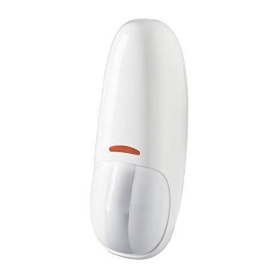
Figure 1. CLIP SMA General View
Figure 4. Overhead Curtain
2. SPECIFICATIONS
OPTICAL
Detector Type: Dual-element low noise pyroelectric sensor.
Number of Curtain Beams: 2
Mounting Positions: See Figures 2 through 6.
Range Settings: Long (6 m/18 ft), Medium (4 m/12 ft) and Short (1.2 -
2m/6 ft) (Jumper-selected).
ELECTRICAL
Internal Battery: 3V Lithium battery, type CR123A. For UL installations,
use Panasonic, GP or Sanyo only.
Nominal Battery Capacity: 1450 mAh.
Battery Life: 3 years (for typical use).
Note: Inability to connect with wireless network, or wireless link quality no
higher than 20% may significantly reduce the expected battery life.
Battery Power Test: Performed immediately upon battery insertion
and periodically every several hours.
Microprocessor: 8-bit, low power CMOS.
FUNCTIONAL
Visual Indications (red LED):
LED lights for about 3 seconds upon transmission of alarm & tamper
messages and upon motion detection in the walk test mode.
LED flashes during the power-up stabilization period (approx. 2
min), or after restoring the cover (by pressing the tamper switch).
LED does not light upon transmission of supervision messages.
Alarm Period: Approx. 3 seconds.
D-303360 CLIP SMA Installer's Guide
After detection, the detector disarms itself to save battery power.
It rearms (reverts to the ready state) if there is no subsequent
detection throughout the following 2-minute period.
The CLIP SMA includes the following features:
Very low current consumption
Microprocessor-controlled temperature compensation
Sealed chamber protects the optical system
Front cover tamper switch
White light protection
Elegantly styled, sturdy case
Detailed coverage patterns and mounting alternatives are
illustrated in Figures 2 through 6.
Figure 2. Wall-Mount Curtain
This
side
up
Figure 5. Curtain / Pet Alley
Rearm Timer: Rearms the detector 2 minutes after the last alarm.
WIRELESS
Frequency: 2.4 Ghz as per IEEE 802.15.4
Tamper Alert: Reported when a tamper event occurs and in any
subsequent message, until the tamper switch is restored.
Supervision Message: Signaling at 24-minute intervals.
MOUNTING
Height: 1.8 - 2.4 m (6 - 8 ft). See Figures 2 – 6.
Installation Options: See Figures 2 – 6.
ENVIRONMENTAL
Operating Temperature: -10°C to 50°C (14°F to 122°F).
Storage Temperature: -20°C to 60°C (-4°F to 140°F).
RFI Protection: > 20 V/m to 1000 MHz.
Compliance with standards:
USA: CFR 47 part 15, Canada: RSS 210
ANSI/UL 639, ULC – S306
PHYSICAL
Dimensions (H x W x D): 105 x 35 x 30 mm (4-1/8 x 1-3/8 x
1-3/16 in.).
Weight (with battery): 60 g (2.1 oz).
Color: White.
PATENTS U.S. Patent 5,693,943 (other patents pending)
Installation Instructions
2.4m
Figure 3. Ceiling-Mount Curtain
OPTION A
DETECTION
CURTAIN
Figure 6. CLIP SMA on Internal Doorframe
.
OPTION B
1
Advertisement
Table of Contents

Related Manuals for Visonic CLIP SMA


Summary of Contents for Visonic CLIP SMA
- Page 1 Installation Instructions Wireless Curtain-Type Infrared Detector 1. INTRODUCTION The CLIP SMA is the smallest and most elegant wireless curtain- After detection, the detector disarms itself to save battery power. pattern PIR detector for indoor use and designed for easy It rearms (reverts to the ready state) if there is no subsequent installation.
-
Page 2: General Guidelines
2) Remove the battery using your fingers, and not with a screwdriver. 3.3 Bracket Mounting Note: When mounting using the bracket, the back tamper is not functional. D-303360 CLIP SMA Installer's Guide... - Page 3 WITH BASE Figure 12. Mounting Cover to Base Figure 10. Mounting Bracket to Surface Note: The CLIP SMA can be mounted on either side of a window. Figure 13. Mounting on Both Sides of a Window D-303360 CLIP SMA Installer's Guide...
-
Page 4: Activating The Detector
Make sure that the signal is sufficient. If necessary, replace the sensor’s battery. The sensor sends a Low To ensure continuous proper Battery indication. operation, replace the battery within two weeks of the first Low Battery indication. D-303360 CLIP SMA Installer's Guide... -
Page 5: Special Comments
5.1 Product Limitations defeated or may fail to warn due to: DC power failure / Visonic Ltd. wireless systems are very reliable and are tested to improper connection, malicious masking of the lens, high standards. However, due to their low transmitting power and... - Page 6 VISONIC LTD (ISRAEL): P.O.B 22020 TEL-AVIV 61220 ISRAEL. PHONE: (972-3) 645-6789, FAX: (972-3) 645-6788 VISONIC INC. (U.S.A.): 65 WEST DUDLEY TOWN ROAD, BLOOMFIELD CT. 06002-1376. PHONE: (860) 243-0833, (800) 223-0020 FAX: (860) 242-8094 VISONIC LTD. (UK): FRASER ROAD, PRIORY BUSINESS PARK, BEDFORD MK44 3WH. TEL.: +44(0)845 0755800 FAX: +44(0)845 0755801 PRODUCT SUPPORT: +44(0)845 755802 www.visonic.com...
-
Page 7: Installation Instructions
MCT-302 SMA Magnetic Contact Wireless Sensor Installation Instructions 1. INTRODUCTION The MCT-302 SMA is a fully supervised, wireless magnetic contact sensor. The sensor An LED lights whenever alarm or tamper events are reported. The LED does not light includes a built-in reed switch (that opens upon removal of a magnet placed near it) and while a supervision message is being transmitted. -
Page 8: Compliance With Standards
VISONIC GmbH (D-A-CH): KIRCHFELDSTR. 118, D-40215 DÜSSELDORF, TEL.: +49 (0)211 600696-0, FAX: +49 (0)211 600696-19 VISONIC IBERICA: ISLA DE PALMA, 32 NAVE 7, POLÍGONO INDUSTRIAL NORTE, 28700 SAN SEBASTIÁN DE LOS REYES, (MADRID), ESPAÑA. TEL (34) 91659-3120, FAX (34) 91663-8468. www.visonic-iberica.es INTERNET: www.visonic.com... -
Page 9: Description And Applications
Battery Life Expectancy: Battery life exceeds the minimum life required by Operating Frequency: 2.4 GHz as per IEEE 802.15.4 UL 268. Visonic warrantees the life of the battery for 5 years for typical use. Supervision: Automatic signaling at 24-minute intervals. Note: Inability to connect with wireless network, or wireless link... - Page 10 Visual Indication (LEDs) Audio 3 volts CR17450 Condition Indication Yellow Heat sensor Flash every 60 5 Flashes every Short beep every trouble sec. 60 sec. 60 sec. Need to clean 2 flashes every 2 short beeps 30 sec. every 30 sec. Test See par.
- Page 11 3.7 LED Transmission Procedure 3.6 Test The yellow LED can be set to ON or OFF by pressing the Enter the test mode by pressing the test button. In this mode, the Transmission LED (yellow) ON/OFF button (see Figure 3a), as detector will test smoke, heat and battery functions.
-
Page 12: Battery Replacement
4.3 Smoke Detector Limitations Do not mount smoke detectors in the path of fresh air intake. The flow of fresh air in and out can drive smoke away from the smoke A. This smoke detector is designed for use in a single residential unit detector;... -
Page 13: Additional Advice
B. Replace battery (see Figure 3a or Figure 3b according to the and audible indications). battery used). Perform detector functional test (see par. 3.6) weekly. 5.2 Maintenance A clean (maintenance) signal is transmitted when the detector's chamber sensitivity becomes degraded. It is necessary to maintain the detector frequently to ensure it working Note: This transmission applies to the PowerMax+ control panel properly. -
Page 14: Statements Of Compliance
VISONIC GmbH (D-A-CH): KIRCHFELDSTR. 118, D-40215 DÜSSELDORF, TEL.: +49 (0)211 600696-0, FAX: +49 (0)211 600696-19 VISONIC IBERICA: ISLA DE PALMA, 32 NAVE 7, POLÍGONO INDUSTRIAL NORTE, 28700 SAN SEBASTIÁN DE LOS REYES, (MADRID), ESPAÑA. TEL (34) 91659-3120, FAX (34) 91663-8468. www.visonic-iberica.es INTERNET: www.visonic.com... - Page 15 MCT-442 SMA Installation Instructions Supervised Indoor Wireless CO Gas Detector 1. INTRODUCTION The carbon monoxide (CO) detector is designed to monitor the The detector provides ALARM CO gas level in residential dwellings and give early warning (red) LED low battery and detector before potentially dangerous levels exist.
-
Page 16: Maintenance
3. PREPARATIONS 3.1 Disassembly B. Insert the battery into the sensor. Wait for the RF module’s green LED to light. BRACKET C. Release the tamper switch and press it again within 4 seconds. When the sensor is in pairing mode, the green LED starts to blink. -
Page 17: Appendix A - Co Detector Installation Overview A-1. Selecting Installation Location
This device complies with Part 15 of the FCC Rules and RSS-210 of Industry and Science Canada. Operation is subject to the following two conditions: (1) This device may not cause harmful interference, and (2) this Visonic Ltd, M/N: E203826 device must accept any interference received, including interference that FCC ID: WP3ZBT may cause undesired operation. -
Page 18: Appendix B - Co Gas Health Effects B-1. Toxic Effects
Appendix B - CO Gas Health Effects B-1. Toxic Effects The following symptoms are related to CO poisoning and are to be discussed with ALL members of the household: Carbon monoxide (CO) is a colorless, odorless non-irritating gas 1. Mild Exposure: Slight headache, nausea, vomiting, fatigue (often which is classified as a chemical asphyxiate whose toxic action is a described as "Flu-like"... -
Page 19: Appendix D - Warnings And Limitations
CO problem. Warning! Changes or modifications to this equipment not expressly approved by Visonic Ltd. could void the user’s authority to operate the equipment. The digital circuit of this device has been tested and found to comply with the limits for a Class B digital device, pursuant to Part 15 of the FCC Rules. - Page 20 Certificate Number 512e/01 TEL.: +44(0)845 0755800 FAX: +44(0)845 0755801 PRODUCT SUPPORT: +44(0)845 755802 VISONIC IBERICA: ISLA DE PALMA, 32 NAVE 7, POLÍGONO INDUSTRIAL NORTE, 28700 SAN SEBASTIÁN DE LOS REYES, (MADRID), ESPAÑA. TEL (34) 91659-3120, FAX (34) 91663-8468. www.visonic-iberica.es INTERNET: www.visonic.com ...
- Page 21 MCT-550 SMA Supervised Wireless Flood Detector Installation Instructions INTRODUCTION The MCT-550 SMA is a fully supervised indoor wireless flood An LED lights whenever alarm or tamper events are reported. The detector, used to detect the presence of water based fluids at LED does not light while a supervision message is being any desired location.
- Page 22 The MCT-550 transmits a coded alarm message immediately following detection of water contact with the food senso r. CLAMP (1 OF 3) Attach slightly above Flood Sensor FLOOD SENSOR MCT-550 WATER ALARM SYSTEM FLOOD SENSOR CABLE Fig. 2 – Using the MCT-550 SMA TRANSMISSION LED COVER CLOSURE SCREW...
-
Page 23: Activating The Detector
Industry and Science Canada. Operation is subject to the following two conditions: (1) This device may not cause harmful interference, and (2) this device must accept any interference received, including interference that Visonic Ltd, M/N: E203826 FCC ID: WP3ZBT may cause undesired operation. - Page 24 FRASER ROAD, PRIORY BUSINESS PARK, BEDFORD MK44 3WH. TEL.: +44(0)845 0755800 FAX: +44(0)845 0755801 PRODUCT SUPPORT: +44(0)845 755802 VISONIC IBERICA SEGURIDAD, SL: C/ ISLA DE PALMA, 32 - NAVE 7, POLÍGONO INDUSTRIAL NORTE, 28700 SAN SEBASTIÁN DE LOS REYES, (MADRID), ESPAÑA. TEL (34) 91659-3120, FAX (34) 91663-8468. www.visonic-iberica.com VISONIC SICHERHEITSTECHNIK GMBH ROMANEYER STR.
- Page 25 NEXT PLUS K9-85 SMA ® Wireless Digital Pet Immune PIR Detector Installation Instructions INTRODUCTION Sealed chamber protects the optical system. The NEXT® PLUS K9-85 SMA (pet immune) is a microprocessor- Front cover tamper switch. controlled wireless digital PIR detector. ...
-
Page 26: Installation Procedure
3.2 Installation Procedure 1. For battery installation, see steps 1-3 below. 2. For mounting the detector, see step 4 below. Push catch and remove board Mounting Insert battery Front Tamper switch Release screw and remove cover On surface In corner Fig. - Page 27 This device complies with Part 15 of the FCC Rules and RSS-210 of Industry and Science Canada. Operation is subject to the following two conditions: (1) This device may not cause harmful interference, and (2) this Visonic Ltd, M/N: E203826 FCC ID: WP3ZBT device must accept any interference received, including interference that IC: 1467C-ZBT may cause undesired operation.
- Page 28 VISONIC GmbH (D-A-CH): KIRCHFELDSTR. 118, D-40215 DÜSSELDORF, TEL.: +49 (0)211 600696-0, FAX: +49 (0)211 600696-19 VISONIC IBERICA: ISLA DE PALMA, 32 NAVE 7, POLÍGONO INDUSTRIAL NORTE, 28700 SAN SEBASTIÁN DE LOS REYES, (MADRID), ESPAÑA. TEL (34) 91659-3120, FAX (34) 91663-8468. www.visonic-iberica.es INTERNET: www.visonic.com...
Need help?
Do you have a question about the CLIP SMA and is the answer not in the manual?
Questions and answers