
Related Manuals for WhisperKool CEILING MOUNT 8000 H.E.


Summary of Contents for WhisperKool CEILING MOUNT 8000 H.E.
- Page 1 CEILING MOUNT 8000 H.E. OWNER'S MANUAL NOTICE: To activate the split system warranty, the installing certified HVAC/R service tech must complete the split system warranty checklist and send back to WhisperKOOL.
- Page 2 WhisperKOOL. Every effort has been made to ensure that the information in this manual is accurate. WhisperKOOL is not responsible for printing or clerical errors.
-
Page 3: Table Of Contents
Table Of Contents Introduction……………………………………………………………………………………....Page 2 Before You Start ……………………………………………………………………………………………. Page 3 Preparing The Wine Cellar………………………………………………………………………………… Page 4 Receiving & Inspecting The System………………………………………………………………………. Page 6 Quick Reference Guide…………………………………………………………………………………….. Page 7 Knockout Locations……………………………………………………………………………....Page 8 Liquid-Measuring Thermostat System( Bottle Probe)-KDT…………………………………………….. Page 9 Items To Route Before Installing The Evaporator Unit-KDT………………………………………………... -
Page 4: Introduction
INTRODUCTION Customer Service Thank you for purchasing a WhisperKOOL cooling system. We strive to provide the highest-quality products and the best possible customer service. If you have any questions about your system, please call us at 1-800-343-9463 or visit WhisperKOOL.com. -
Page 5: Before You Start
8. WhisperKOOL requires that all split systems be installed by a certified HVAC-R technician only. NATE or equivalent is recommended. If you encounter a problem with your WhisperKOOL system, please refer to the Troubleshooting Guide. If you have any further questions or concerns, or need assistance, please contact WhisperKOOL's Customer Service at 1-800-343-9463. Please be sure all testing has been completed prior to contacting Customer Service. -
Page 6: Preparing The Wine Cellar
PREPARING THE WINE CELLAR The performance and life of your system is contingent upon the steps you take in preparing the wine cellar. Improp-erly preparing your enclosure or incorrectly installing your unit may cause unit failure, leaking of condensation, and other negative side effects. It is highly recommended that you obtain the assistance of a wine storage professional. - Page 7 PREPARING THE WINE CELLAR, CONTINUED Unobstructed Airflow Unobstructed airflow to and from the system is critical for the evaporator unit and condensing units overall performance and lifespan. A minimum of 3 feet of clearance (5 feet is ideal) on all sides is crucial. The air the fans blow needs to circulate and either dissipate or absorb heat from the space.
-
Page 8: Receiving & Inspecting The System
Allow the condensing unit to sit for 24 hours prior to start-up. The condensing unit can be placed in the installation location, piped and evacuated during this time. Note: WhisperKOOL units are manufactured in the USA and tested prior to shipment. •... -
Page 9: Quick Reference Guide
QUICK REFERENCE GUIDE QUICK REFERENCE GUIDE Bottom View Evaporator Unit (Fan Coil Unit) Line Set Knockout (x6) Electrical Knockouts Supply and Return Grille (Paintable) Mounting Bracket (Paintable) Top View Top Panel Optional Line Set and Line Set Knockout Electrical Openings Options Electrical Knockout Options... -
Page 10: Knockout Locations
KNOCKOUT LOCATIONS KNOCKOUT LOCATIONS 15.35" 20.40" 4.55" 1.50" 14.10 Top View of Evaporator Unit 8.05" 2.81" 3.75" 3.00" 1.42" 34.33" 35.75" 15.35" 20.40" 4.58" 1.50" 12.65" Side View of Evaporator Unit 12.65" 6.58" 1.75" 35.75" PROPRIETARY AND CONFIDENTIAL 14.10" 14.10" 11.10"... -
Page 11: Liquid-Measuring Thermostat System( Bottle Probe)-Kdt
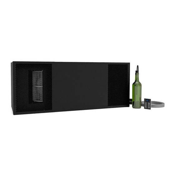
LIQUID-MEASURING THERMOSTAT SYSTEM (BOTTLE PROBE) - KDT Our cooling units come with a liquid-temperature-measuring thermostat. The self-calibrating probe con-tains a sensor chip, which communicates back and forth with the thermostat. This results in a consistent temperature setting and accuracy. Wine should be kept at a very precise, controlled temperature and humidity. -
Page 12: Items To Route Before Installing The Evaporator Unit-Kdt
ITEMS TO ROUTE BEFORE INSTALLING THE EVAPORATOR UNIT - KDT Route the line set from the condensing unit to the desired evaporator unit installation location. Route the display cable from the desired location to the evaporator installation location. Route the bottle probe cable from the desired thermostat bottle location to the evaporator unit installation location. -
Page 13: Thermostat Conversion Kit Wiring Instructions
24V THERMOSTAT KIT WIRING INSTRUCTIONS The 24V thermostat conversion kit requires a standard 18-5 thermostat wire to be run from the evaporator unit to the thermostat. The white wire will not be used, as there is no heating function. (Some thermostats need a common wire and some do not;... -
Page 14: Selecting Mounting Options
SELECTING MOUNTING OPTION Minimum Tools Needed: T-square Hammer #2 Phillips-head screwdriver Locate the desired installation location. Using a stud finder, locate the ceiling joists on either side of the center point. Cut and frame an opening in the ceiling measuring 14.5” x 36”. Make sure the framing is sufficient to support the weight of the cooling unit. -
Page 15: Mounting The Evaporator Unit
MOUNTING THE EVAPORATOR UNIT Secure the mounting bracket to the unit using the twelve (12) supplied 3/8” s Philips pan-head screws. NOTE: You are REQUIRED to use only the mounting locations provided. These locations ensure that the installer will not drill into any copper or electrical wiring within the system. Unscrew the eighteen (18) screws and remove the top and electrical access panels. -
Page 16: Preparing The Evaporator Unit
INSTALLING THE EVAPORATOR UNIT 6. Using copper tubing per line set sizing chart, route the liquid and suction lines to the tubing coming from the unit 7. Connect the line set to system using the line set connection instructions 8. Insulate the suction line using Armaflex or similar insulation. 9. -
Page 17: Installing The Evaporator Unit
INSTALLING THE EVAPORATOR UNIT WITH ATTIC ACCESS 11. Slide the electrical panel out from the unit. 12. Connect the end of the straight black bottle probe cable to the circular connector on the exterior of the electrical box Connect the end of the display cable labeled “UNIT” to the wire labeled “UNIT” coming from the electrical box. 14. -
Page 18: Connecting The Lineset
CONNECTING THE LINESET Connect the refrigerant piping according to these instructions 1. When cutting the pipes make sure to take extra care and cut and flare them properly. This will ensure a proper connection and minimize the need for maintenance a. - Page 19 CONNECTING THE LINESET, CONTINUED PIPING EXTENSION BEYOND FLARE FORM Flare form Outer Diameter of A (in.) Pipe (in) Max. Min. Ø 1/4” 0.0275” 0.05” Ø 3/8” 0.063” 0.04” Ø 1/2” 0.04” 0.07” Ø 5/8” 0.078” 0.086” 0.078” 0.094" Ø 3/4” Pipe e.
-
Page 20: Insulation Blanket Installation
INSULATION BLANKET INSTALLATION *Tools required: spray adhesive, utility knife, foil tape Mini Ceiling Mount blanket dimensions 68” 22” Insulation Blanket Insulation Blanket 11.25” 11” Ceiling Mount blanket dimensions 102” 35.75” Insulation Blanket Insulation Blanket 14.25” 14.25” 1. Once mounting bracket location has been selected and installed, proceed to the insulation blanket installation. 2. - Page 21 INSULATION BLANKET INSTALLATION, CONTINUED 7. Spray the top of the evaporator unit with spray adhesive. (See spray adhesive directions for proper tack time before proceeding to step 8.) 8. Set piece (B) in place by pressing firmly on all surfaces of the insulation that come in contact with the top of the evaporator unit (see illustration).
-
Page 22: Drain Line
1/4" Clear Plastic Tubing Rigid drain line Proper Discharge Location WRONG: Drain line is under water. To prevent mold from growing, allow the drain line to hang above the water line. Page 20 www.whisperkool.com | Page 21... -
Page 23: Wall Mount Bracket Installation
REMOTE DISPLAY: INSTALLATION AND CONFIGURATION* Tools needed:5/16" drill bit, 3/16" drill bit, drywall saw, level, pencil What’s included: Display panel, wall mount bracket, flush mount bracket, flush mount template °F Display panel Wall mount bracket Flush mount bracket Flush mount template WALL MOUNT BRACKET INSTALLATION 1. - Page 24 WALL MOUNT BRACKET INSTALLATION, CONTINUED 2. Using a drill with a 3/ 1 6 ” bit, drill four holes in the drywall for the screws. Insert the four (4) provided drywall anchors into the drywall, then tap them in with a hammer until they are flush with the wall. 3.
- Page 25 WALL MOUNT BRACKET INSTALLATION, CONTINUED NOTE: Before you continue to Step 4, locate the area where the display will be mounted. You may route the display wire into the housing one of three ways: either through the wall or through one of the holes on the top or bottom edges of the wall mount bracket.
-
Page 26: Flush Mount Bracket Installation
FLUSH MOUNT BRACKET INSTALLATION 1. Square the flush mount template on the wall 2. Peel the backing off the template and stick it to the wall, using a level. Then draw a 3” line along the aligning the bottom edge with the line drawn in Step 1. bottom edge of the template. - Page 27 FLUSH MOUNT BRACKET INSTALLATION, CONTINUED 5. Remove the backing from the double-sided tape on the flush mount bracket. 6. Align magnets with previously drilled holes. Make sure the cut-out portion of the bracket (circled below) is on the bottom. Press the bracket firmly against the wall. WALL HOLE CUTOUT...
- Page 28 FLUSH MOUNT BRACKET INSTALLATION, CONTINUED 7. Connect the end of the display cable to the JST connector on the display panel. DISPLAY BRACKET 8. Place the display on the flush mount bracket as shown, attaching the back of the display panel to the magnets on the mounting bracket.
-
Page 29: Evaporator Unit Wiring Diagram - Kdt
CEILING MOUNT WIRING DIAGRAM - KDT ELIWELL RTN400 KDT PLUS DISPLAY CPB Pb3 CPB Pb2 CPB Pb1 KEYB NEUTRAL LINE OUT 2 OUT 3 OUT 4 NEUTRAL LINE OUT 1 WHITE BLACK BLACK BLACK BLACK BLACK RESERVOIR CONDENSATE PUMP BLACK BLUE BLACK BLACK... -
Page 30: Evaporator Unit Wiring Diagram - 24V
CEILING MOUNT WIRING DIAGRAM - 24V LEGEND Field Installed Factory Installed Thermostat Blue Blue Green Green Yellow 1 2 3 4 5 Blue Relay Yellow Transformer 24V Wires to Condensing Unit Black Black White Reservoir Unit Ground Stud 1 2 3 4 Green Condensate Pump... -
Page 31: Condensing Unit Wiring Diagram
CONDENSING UNIT WIRING DIAGRAM Yellow White Black Brown Gray Blue Page 29... -
Page 32: Line Set Piping Diagram
LINE SET PIPING DIAGRAMS Reverse oil return bend These are two suggested examples Downward slope Oil saving bend for running the line set from the coil pitched toward to the condensing unit. Example 1 Evaporator compressor " / 10' is specifically applicable when Coil the system is installed with the condensing unit below or leveled to... -
Page 33: Preparing The Condensing Unit
Troubleshooting Guide. Communication Cable Operation WhisperKOOL’s split systems operate like traditional air conditioners where there is wiring between the condensing unit and the evaporator unit. WhisperKOOL Cassette Condensing Unit systems do not utilize a solenoid valve or low-pressure switch, which allows the system to run like a residential HVAC system. -
Page 34: Condensing Unit Wiring
CONDENSING UNIT WIRING 1. Locate or install an electrical disconnect box near the outdoor condensing unit per electrical code. 2. Remove electrical cover plate from unit. 3. Connect wiring for: 24V contactor (communication cable), L1, L2, and Ground as identified by terminal block label. 4. -
Page 35: Installing The Condensing Unit
INSTALLING THE CONDENSING UNIT Step 1: Select installation location Before installing the outdoor unit, you must choose an appropriate location. The following are standards that will help you choose an appropriate location for the unit. Proper installation locations meet the following standards: •... - Page 36 INSTALLING THE CONDENSING UNIT(CONTINUED) If you will install the unit on the ground or on a concrete mounting platform, do the following: 1. Mark the positions for four expansion bolt based on dimensions in the Unit Mounting Dimensions chart. 2. Pre-drill holes for expansion bolts. 3.
- Page 37 INSTALLING THE CONDENSING UNIT (continued) Line Set Piping Size Line Set Length <25ft 26-50ft 50-100ft Ceiling Mount 8000 Horizontal Tubing 1/2” 5/8” Suction Line Vertical Rise 1/2” 1/2” Horizontal Tubing 1/4” Liquid Line Vertical Rise 1/4” Line set piping size is determined by the unit size and the line set length. Determine the length before selecting the size. For the vertical rise on the suction and liquid lines refer to the line set piping diagrams above.
- Page 38 INSTALLING THE CONDENSING UNIT(continued) Charging • The chart below provides the approximate refrigerant charge amount for initial startup based on the line set length. Please see the chart below for the initial charge amount. The installing technician may still need to add additional charge and dial in the desired subcooling to achieve optimum performance.
- Page 39 INSTALLING THE CONDENSING UNIT(continued) Finalizing the Installation • Confirm the entire suction line from the evaporator unit to the condensing unit is insulated using cellular insulation or equivalent. Seal all seams with Armaflex 520 Foam Insulation Adhesive or equivalent. • Confirm that the control is displaying the correct temperature and that no alarms are present. Approximate Operating Pressures (Cellar temperature 55°F) Temp.
-
Page 40: Display Layout And Specifications
QUICK REFERENCE GUIDE Compressor is on Display Layout Fan is on Anti-Frost Cycle running Alarm is present °F Scroll Button Return to Previous Menu Change Setpoint View/Change Setpoint Scroll Button Enter User Menu Change Setpoint Power On/Off Unlock Button (hold for 5 sec) (hold for 1 sec) CEILING MOUNT 8000 SPECIFICATIONS Ceiling Mount 8000... -
Page 41: Finalizing The Installation
FINALIZING THE INSTALLATION Push the grille back into place. This will attach the grille to the ball studs. Screw in the eight screws to secure the front access panel. Page 39... -
Page 42: Filter
FILTER Washable filter is installed from the factory on the return side of the grille, secured via Velcro strips. Page 40... -
Page 43: Line Set, Drain Tube, And Electrical Connections
LINE SET, DRAIN TUBE, and ELECTRICAL CONNECTIONS • Line set, drain tube and electrical connections have been relocated to be accessible from the bottom (cellar side / grille side) located on return side of unit. • Can be accessed by removing the grille. •... -
Page 44: Speed Switch
2 SPEED SWITCH • The WhisperKool Ceiling mount now comes equipped with a 2-speed fan switch. • Located on the electrical panel. Access by removing grille and internal access panel. • Speed is sent from factory set to High. Flip the switch to adjust down to Medium speed. -
Page 45: Controller Functions
CONTROLLER FUNCTIONS Button Normal Functions °F INITIAL STARTUP When the unit is plugged in and power is sent to the controller, a beep will sound, confirming that the controller is getting power. All LEDs on the display will blink three times. Three dashes will then appear on the screen. -
Page 46: Icon Glossary
ICON GLOSSARY Icon Meaning SNOWFLAKE Blinking: The unit is calling for cooling, but must wait five minutes before restarting the com- pressor. This five-minute delay serves as an Anti-Short Cycle for the compressor’s protection. Constant: The unit is in cooling mode and the condensing unit is running. DRIPPING SNOWFLAKE The unit is undergoing an Anti-Frost Cycle. -
Page 47: Alarm Codes
ALARM CODES Code Cause Solution The following alarm codes will be displayed on the screen along with the alarm icon. Bottle probe is not connected Attach bottle probe to circular connector Faulty bottle probe connection Locate faulty bottle probe connection by inspecting all wiring connections between the bottle probe and the circuit board. -
Page 48: User Menu
USER MENU The User Menu is accessed by pressing and holding the SET button for 3 seconds. Use the UP and DOWN ARROW buttons to navigate to desired parameters. Press the SET button again to view these parameters. Press the UP and DOWN ARROW buttons to adjust a parameter. -
Page 49: Troubleshooting Guide
WHISPERKOOL TROUBLESHOOTING GUIDE Unit has ice forming on the evaporator unit Possible cause Solution Evaporator filter or coil is dirty Remove the filter and wash it, then clean the coil with a vacuum. If coil is very dirty, use a spray bottle with a small amount of liquid dish detergent or coil cleaner. - Page 50 Unit leaks water Possible cause Solution Evaporator unit is not level Evaporator unit should be level on the wall to prevent leaking Drain line clogged or kinked Check drain line to make sure water can flow freely Drain is clogged, preventing water from escaping Disconnect drain and clear it out;...
-
Page 51: Bypass Test Procedure
BYPASS TEST PROCEDURE NOTE: If instructed by a WhisperKOOL representative, follow the directions below to test the cooling unit using the bypass plug provided in the accessory kit. 1. Disconnect power from the evaporator unit. 2. Loosen the two (2) screws on the front of the grille or duct plenum. -
Page 52: System Operation-Kdt
SYSTEM OPERATION-KDT Initial Start-Up The compressor will remain off until the evaporator coil reaches 40°F, or for a maximum of one hour. The unit will then When the unit is plugged in and power is sent to the controller, a beep will sound, confirming that the controller is getting return to normal operation. -
Page 53: System Operation-24V
SYSTEM OPERATION-24V Initial Start-Up Set the thermostat to COOL and fan switch to AUTO. Lower the setpoint to the desired cellar temperature. (A temperature of 55°F is the recommended setpoint.) See thermostat instructions for details. Indoor Fan Operation If the fan switch on the thermostat is in the AUTO position, it will run only during the cooling cycle. -
Page 54: Maintenance Schedule
MAINTENANCE SCHEDULE Monthly 1. Check for debris surrounding condensing unit (leaves, branches, trash, etc); remove all obstructions 2. Check for unusual noise or vibration 3. Check the drain line to see if it is above the waterline (if draining into a vessel) Semi - 1. -
Page 55: Technical Assistance
TECHNICAL ASSISTANCE WhisperKOOL Customer Service is available Monday through Friday from 6:00 a.m. to 4:00 p.m. Pacific Standard Time. The appointed customer service representative will be able to assist you with your questions and warranty information more effectively if you provide them with the following: •... -
Page 56: Warranty Information
WhisperKOOL warrants against defects in material and workmanship as follows: 1. LABOR — For a period of two (2) years commencing on the date of purchase, WhisperKOOL will, at its option and discretion, reimburse up to $250 to the End User for cost incurred for servicing, repairing, removing or installing warranty parts. - Page 57 6. Proof of purchase of the Product in the form of a bill of sale, receipted invoice or serial number, which is evidence that the Product is within the Limited Warranty Period, must be presented by the End User to WhisperKOOL in order to obtain limited warranty service.
- Page 58 WhisperKOOL Customer Service to arrange for replacement under the warranty guidelines. When a claim for warranty is submitted for a condenser skid, the End User must purchase a new condenser skid from WhisperKOOL at retail price. Upon installation of the new condenser skid by a certified HVAC/R Technician, the HVAC/R Technician must complete the Installation Checklist and End User must submit the Installation Checklist to WhisperKOOL Customer Service for approval.
- Page 59 County of San Joaquin, State of California, and all parties, WhisperKOOL, Purchaser and End User, hereby irrevocably submit to the personal jurisdiction of such courts for that purpose. No waiver by WhisperKOOL of any breach or default of the contract of sale (including these Terms and Conditions of Sale) concerning a Product will be deemed to be a waiver of any preceding or subsequent breach or default.
-
Page 60: Warranty Registration
WhisperKOOL 209-466-4606 warranty@whisperkool.com B. Technical Assistance. WhisperKOOL Customer Service is available Monday through Friday from 6:00 a.m. to ATTN: Warranty Registration 4:00 p.m. PST. The Customer Service representative will be able to assist you with your questions and warranty 1738 E. Alpine Avenue... - Page 61 WhisperKOOL 1738 E. Alpine Ave Stockton, CA 95205 1(800) 343-9463 www.whisperkool.com...
Need help?
Do you have a question about the CEILING MOUNT 8000 H.E. and is the answer not in the manual?
Questions and answers