Table of Contents
Advertisement
Quick Links
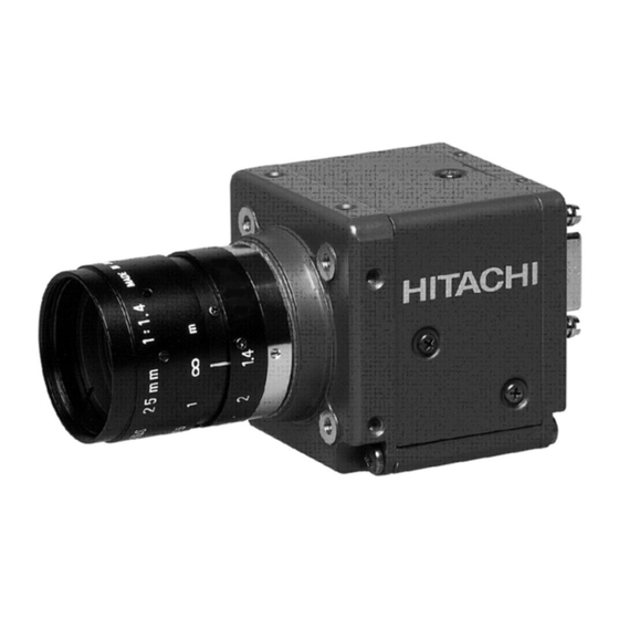
CCD color camera
KP-FD510WCL
Operation Manual
Thank you for purchase this fine Hitachi Kokusai Electric CCD camera.
Before using the camera, please read this operation manual carefully.
Hitachi Kokusai Electric Inc.
RoHS Compliant
These products comply with the requirement of the RoHS (Restriction of the
use of Certain Hazardous Substances in Electrical and electronic Equipment)
Directive 2002/95/EC.
The 1st edition in October, 2013.
Advertisement
Table of Contents

Related Manuals for Hitachi Kokusai Electric KP-FD510WCL


Summary of Contents for Hitachi Kokusai Electric KP-FD510WCL
- Page 1 CCD color camera KP-FD510WCL Operation Manual Thank you for purchase this fine Hitachi Kokusai Electric CCD camera. Before using the camera, please read this operation manual carefully. Hitachi Kokusai Electric Inc. RoHS Compliant These products comply with the requirement of the RoHS (Restriction of the use of Certain Hazardous Substances in Electrical and electronic Equipment) Directive 2002/95/EC.
- Page 2 IMPORTANT SAFETY INSTRUCTIONS 1. Read Instructions All the safety and operating instructions should be read before the product is operated. 2. Retain Instructions The safety and operating instructions should be retained for future reference. 3. Heed Warnings All warnings on the product and the operating instructions should be adhered to. 4.
- Page 3 WICHTIGE SICHERHEITSANWEISUNGEN 1. Alle Anweisungen lesen Vor Betrieb des Erzeugnisses sollten alle Sicherheits-und Bedienungsanleitungen gelesen werden. 2. Die Anweisungen aufbewahren Die Sicherheits-und Bedienungsanleitungen sollten fünftigen Bezug aufbewahrt werden. 3. Warnungen beachten Die Warnungen auf dem Erzeugnis und in den Bedienungsanleitungen solten beachtet werden. 4.
- Page 4 MISES EN GARDE IMPORTANTES 1. Lire les instructions Lire toutes les instructions de sécurité et de fonctionnement avant de faire fonctionner l’appareil. 2. Conserver ces instructions Conserver les instructions de sécurité et de fonctionnement á des fins de référence ultérieure. 3.
- Page 5 IMPORTANT NOTICE For U.S.A. These products have been tested and found to comply with the limits for a Class A digital device, pursuant to Part 15 of the FCC Rules. These limits are designed to provide reasonable protection against harmful interference when the equipment is operated in a commercial environment.
- Page 7 Phenomena inherent to CCD imaging device The following phenomena are inherent to a charge coupled device imaging element and do not indicate malfunction. Smear and blooming Vertical bands are visible when a strong light enters the scene. Adjust the camera aiming direction carefully to avoid strong direct or reflected light.
-
Page 8: Table Of Contents
Table of Contents 1. Overview ···················································································································· 1 2. Standard Composition ··································································································· 1 3. Features ····················································································································· 1 4. System example ··········································································································· 1 5. Section name and functions ···························································································· 2 6. Camera mounting ········································································································· 2 7. Lens ·························································································································· 2 8. Optical filter ················································································································· 3 9. -
Page 9: Overview
Overview KP-FD510WCL is CameraLink output type color camera which utilized the progressive scan CCD image sensor with square pixel which adopted the RGB primary color mosaic filter. Because square pixel CCD is adopted, the image that is appropriate for the picture processing is obtained. -
Page 10: Section Name And Functions
Section name and functions Camera / Tripod adaptor mounting screw holes CameraLink connectors Use for digital video output Lens mount and camera control signal (C mount) input/output signal. DC IN/SYNC connector Use for DC+12V power or external trigger/VD signal input. Camera / Tripod adaptor mounting screw holes Camera mounting... -
Page 11: Optical Filter
Optical filter How to remove the IR cut filter. (1) Remove two screws ① and filter holder ② will come off. (2) Remove the IR cut filter ③ from filter frame ④. (3) Then, reinstall and secure filter holder ② with two screws ①. Note: Prior to removing the optical filter, be sure to turn off the power. -
Page 12: Connector
Connector 1. CameraLink connector D.OUT 1 (Connector 1) Pin No. Signal Pin No. Signal +12V (PoCL) GND (non-PoCL) TXOUT 0 (-) TXOUT 0 (+) TXOUT 1 (-) TXOUT 1 (+) TXOUT 2 (-) TXOUT 2 (+) TXCLKOUT (-) TXCLKOUT (+) TXOUT 3 (-) TXOUT 3 (+) RX (+) [ SERTC (+) ]... -
Page 13: Functions And Operations
Functions and operations Various mode setup and adjustment of KP-FD510WCL is performed by the remote control via CameraLink. Operation and adjustment way of function utilized are described below. See "Remote control" (page 9 to 15) and "Command list" (page 16 to 19) about communication method of each command. - Page 14 Ex.1 Exposure time = setting value nnn to obtain 1/125 second (= 8000μsecond). − 8000 ⎛ ⎞ ⎛ ⎞ 8000 ⎜ ⎜ ⎟ ⎟ ⎜ − ⎟ × ⎝ ⎠ ⎝ ⎠ ⎛ ⎞ × ⎜ ⎟ ⎝ ⎠...
- Page 15 OFF (Factory setting) : Not perform knee. : Knee function provides natural gradation in bright portions. -KNEE POINT- : Adjust knee point 0 (Factory setting) to 32 : Setting value toward 0 side increase start level of knee and 32 side decrease start level of knee. -KNEE SLOPE- : Adjust knee slope 0 (Factory setting) to 159 : Setting value toward 0 side intensify effective of knee and 159 side weaken effective of knee.
- Page 16 (15) PAINT BLACK : Setting of paint black (color level of R, G, and B can be separately varied). -MODE- : Select of mode OFF (Factory setting) : Not use paint black functions. : Use paint black functions. -RED- : Adjust red color level 0 (Factory setting) to 255 : Adjust red color level in 256 steps.
-
Page 17: Remote Control
Remote control 1. Comms* specifications ・Control system : Start-stop synchronization system ・Transmission rate : 9600 bps ・Data length : 8 bit ・Star bit : 1 bit ・Stop bit : 1 bit ・Parity : None ・Bit transfer : LSB first *Comms: Communications 2. - Page 18 ACK code (06H) HITACHI Transmit data (ASCII code) ACK code (06H) Slave (KP-FD510WCL) Master (Machine) ① Session starts when ENQ is sent from master to slave. ② Slave acknowledges by returning ACK to master. ③ Master sends data to slave.
- Page 19 HITACHI NACK code (15H) ENQ code (05H) Slave NACK code (15H) (KP-FD510WCL) ENQ code (05H) Master (Machine) NACK code (15H) ① Master sends ENQ code to slave. ② Since ACK code cannot be sent, slave sent NACK code to master.
- Page 20 Send data (ASCII code) HITACHI 3 second elapse Send data (ASCII code) Slave 3 second (KP-FD510WCL) elapse Send data (ASCII code) Master (Machine) 3 second elapse Send data (ASCII code) ① Session starts when ENQ is sent from master to slave.
- Page 21 (6) Transmission frame error (Master receive) ENQ code (05H) ACK code (06H) Read command (ASCII code) HITACHI ACK code (06H) Read data (ASCII code) Slave (KP-FD510WCL) 3 second elapse Read data (ASCII code) Master (Machine) 3 second elapse Read data (ASCII code)
- Page 22 2 byte (ASCII code) Used for EEPROM write (0: write absent, 1: write present). ・ID No. : Camera peculiar ID. KP-FD510WCL has (FFH). 2 byte (ASCII code) ・Area address : Classification of Send data (01H) and Read command (81H). 2 byte (ASCII code) ・Relative No.
- Page 23 (2) Read (receive) data (slave to master) (a) Command data are converted into ASCII code and transmitted. (b) Comms byte quantity is 10. (c) Comms data format (transmission sequence) E T X S U M S T X Text data 1 byte 6 byte 1 byte...
-
Page 24: Command List
Command list 1. Send data (setting command, Note: 1 to 7 and SUM need to be transformed into ASCII code) Item AREA RELATIVE ETX SUM STATUS ID NO. DATA ADDRESS FIXED MODE 1TRIG VD CONT TRIGGER POSITIVE POLARITY NEGATIVE CL-CC1 SOURCE 12pin OUTPUT SIGNAL... - Page 25 Item AREA RELATIVE STATUS ID NO. DATA ADDRESS MODE MANUAL AWC ADJUST (*5) WHITE BALANCE MIN (0) R-GAIN MAX (255) MIN (0) B-GAIN MAX (255) MODE MIN (0) R-SATURATION MAX (255) MIN (0) R-HUE MAX (255) MIN (0) Cy-SATURATION MAX (255) MIN (0) Cy-HUE MAX (255)
- Page 26 Item AREA RELATIVE STATUS ID NO. DATA ADDRESS MODE MANUAL AUTO MIN(-1.1456dB) BALANCE RIGHT GAIN ADJUST (*9) MAX(+1.1456dB) MIN(-128/2048) RIGHT BLACK 0/2048 (*9) MAX(+127/2048) TEST PATTERN FACTORY SETTING (*9) RIGHT GAIN and RIGHT BLACK are effective only when BALANCE ADJUST MODE is MANUAL.
- Page 27 2. Read-out command (Note: 1 to 7 and SUM need to be transformed into ASCII code) Item AREA RELATIVE STATUS ID NO. DATA ADDRESS MODE TRIGGER POLARITY SOURCE OUTPUT SIGNAL PRESET SHUTTER SPEED VARIABLE VALUE DATA BIT VD / FVAL HD / LVAL GAIN LEVEL MODE...
-
Page 28: Cameralink Output Timing Chart
CameraLink output timing chart 1. Horizontal timing 2568 clk 2448 clk VIDEO Active Picture LVAL 100clk 1clk=15.625ns 12clk 8clk 2. Vertical timing 2079 H 2050 H Active Picture VIDEO FVAL 1H=40.125μs... - Page 29 3. Transmitter LVDS output pulse position measurement (1) Base Configuration (a) 24bit D.OUT 1 : 15.625ns (64.0000MHz) CLKX Previous Cycle Next Cycle R7-1 R6-1 N.U. B3-1 B2-1 N.U. FVAL LVAL (VD) (HD) G2-1 G1-1 R1-1 R0-1 N.U.: Not used When using at Base configuration, please be sure to connect CameraLink cable to D.OUT 1. If the cable is connected to D.OUT 2, machine may break down.
- Page 30 (2) Medium Configuration (a) 30bit D.OUT 1 : 15.625ns (64.0000MHz) CLKX Previous Cycle Next Cycle R7-1 R6-1 N.U. N.U. N.U. B3-1 B2-1 N.U. FVAL LVAL (VD) (HD) N.U. R9-1 N.U. N.U. R1-1 R0-1 N.U.: Not used D.OUT 2 : 15.625ns (64.0000MHz) CLKY Previous Cycle Next Cycle...
- Page 31 (b) 36bit D.OUT 1 : 15.625ns (64.0000MHz) CLKX Previous Cycle Next Cycle R7-1 R6-1 N.U. B3-1 B2-1 N.U. FVAL LVAL (VD) (HD) R10-1 R9-1 R1-1 R0-1 N.U.: Not used D.OUT 2 : 15.625ns (64.0000MHz) CLKY Previous Cycle Next Cycle N.U. N.U.
-
Page 32: Trigger Operation And Timing Chart
Trigger operation and timing chart 1. Normal mode Shutter time (Camera setting value) Shutter time Data output 2079H (*1) 10H (*2) 16H (*3) FVAL 2050H (*4) When partial scan mode (20 + Width + (2071 - Width) / 4) H (1 + (2071 - Width) / 4 - Start / 4) H (16 + Start / 4) H (Width) H... - Page 33 2. Fixed shutter mode When external trigger signal is POSITIVE (high active), after the trigger signal rise, exposure is start. The exposure time is set by the camera electronic shutter speed. The video output is obtained immediately after the end of fixed exposure. The strobe signal start/end can be set to shutter time.
- Page 34 3. ONE trigger mode When external trigger signal is POSITIVE (high active), after the trigger signal rise, exposure is start. At the trigger signal falling edge, the internal VD signal is reset and the video data are transmitted. The trigger signal width equals the exposure time.
-
Page 35: Input / Output Signal
NOTE: If the external VD of cycle which does not match the camera operation mode is input, shutter time has an error. Input / Output signal 1. Input signal The level of the trigger signal input to KP-FD510WCL is as follows. (1) Input from CameraLink cable LVDS level. -
Page 36: Spectral Response
Spectral response ・KP-FD510WCL IR cut filter... -
Page 37: Specifications
Specifications Specifications of KP-FD510WCL is showing. KP-FD510WCL Imaging device 2/3-inch interline CCD Total pixels 2536 (H) x 2068 (V) Effective pixels 2456 (H) x 2058 (V) Active pixels 2448 (H) x 2050 (V) Pixel pitch 3.45μm (H) x 3.45μm (V) -
Page 38: Dimensions
Dimensions ・MASS: APPROX 110 g ・MASS: APPROX 110g ・UHIT: mm ・UNIT: mm ・SCALE: NTS ・SCALE: NTS ±0.5 ±1 10.5 3×2-M3(DEPTH:3) 34 2-M2(DEPTH:3) ±0.5 44 ±0.5 ±1.5 28 4-M3(DEPTH:6) 47 ±0.5 0.5 22 6 40.5 D.OUT 1 D.OUT 2 DC IN/SYNC COLOR:BLACK COLOR:BLACK ±1 10.5... - Page 39 UDX Akihabara Bldg. 14-1 Sotokanda 4-choume, Chiyoda-ku, Tokyo 101-8980, Japan Phone: +81(0) 3-6734-9432, Fax: +81(0) 3-5209-5942 URL: http://www.hitachi-kokusai.co.jp Hitachi Kokusai Electric (Shanghai) Co., Ltd. Beijing Branch : Room 1413, Beijing Fortune Building, 5 Dong San Huan Bei-Lu, Chao Yang District, Beijing, 100004 China Phone: +86(0) 10-6590-8755/8756, Fax: +86(0) 10-6590-8757 Hitachi Kokusai Electric America, Ltd.
Need help?
Do you have a question about the KP-FD510WCL and is the answer not in the manual?
Questions and answers