Jolly Mec BOTERO2 Installation, Use And Maintenance Manual

Jolly Mec BOTERO2 Installation, Use And Maintenance Manual

Pellet operated air heating stove

Advertisement

Quick Links

BOTERO2 8 kW, BOTERO2 10 kW, CHRISSIE
ODETTE 6 kW, ODETTE 8 kW, ODETTE 10 kW
BOTERO2 8 kW UP, BOTERO2 10 kW UP
CHRISSIE UP, ODETTE 6 kW UP
ODETTE 8 kW UP, ODETTE 10 kW UP
BOTERO2 8 kW UP/C, BOTERO2 10 kW UP/C
CHRISSIE UP/C, ODETTE 8 kW UP/C
ODETTE 10 kW UP/C
INSTALLATION, USE AND
MAINTENANCE MANUAL
To be kept by the purchaser
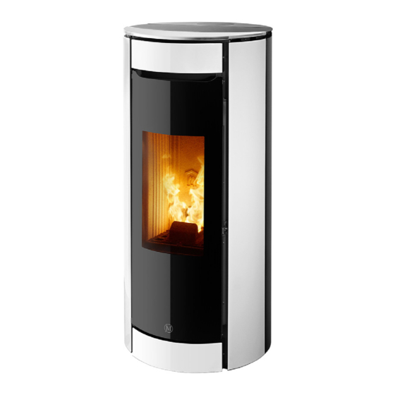
Botero2
Odette
Chrissie
Pellet operated air heating stove

Advertisement

Table of Contents
loading
Need help?

Need help?

Do you have a question about the BOTERO2 and is the answer not in the manual?

Questions and answers

Subscribe to Our Youtube Channel

Summary of Contents for Jolly Mec BOTERO2

  • Page 1 BOTERO2 8 kW, BOTERO2 10 kW, CHRISSIE ODETTE 6 kW, ODETTE 8 kW, ODETTE 10 kW BOTERO2 8 kW UP, BOTERO2 10 kW UP CHRISSIE UP, ODETTE 6 kW UP ODETTE 8 kW UP, ODETTE 10 kW UP BOTERO2 8 kW UP/C, BOTERO2 10 kW UP/C...
  • Page 2 Dear Customer, thank you for having chosen to heat and save with a Jolly Mec product. Please carefully read and keep this sheet before using the equipment. This sheet provides necessary information and suggestions on how to correctly install, use, clean and maintain the product.
  • Page 3: Table Of Contents

    TABLE OF CONTENTS CHAP.01 PREMISES........................... 4 01.1 WARNINGS ..............................4 01.2 SYMBOLOGY ............................... 5 01.3 APPLIED STANDARDS ..........................5 01.4 USE AND STORING OF THE INSTALLATION AND MAINTENANCE MANUAL ........6 01.5 MANUFACTURER LIABILITY AND WARRANTY CONDITIONS ..............6 CHAP.02 ACCIDENT PREVENTION / SAFETY REGULATIONS .............. 7 02.1 GENERAL CONSIDERATIONS ........................
  • Page 4: Chap.01 Premises

    CHAP.01 PREMISES 01.1 WARNINGS • Familiarity and compliance with the instructions given in this manual will ensure quick installation and correct use of the appliance. • Read the manual attentively before commencing installation, and be certain to follow the directions it contains, otherwise the war- ranty could be invalidated and the performance and safety of the appliance jeopardized. • The installation manual is an integral part of the product and must be given to the user. • It must be kept in a safe place and consulted carefully, as all of the warnings provide important information on safety during instal- lation, use and maintenance. • Incorrect installation of the appliance could cause damage and injury to people or animals, for which the manufacture cannot not be held liable. • Installation shall be performed by qualified operators in accordance with the regulations in force in the Country of installation. • The manufacturer declines any contractual or non-contractual liability for damages caused by errors in installation or use of the appliance or failure to follow the instructions contained in this manual. • All rights on the reproduction of this technical manual are owned by Jolly Mec Caminetti S.p.A. The descriptions and illustrations provided in the following publication are not binding. • reserves the right to make any modifications that may be deemed appropriate. • Jolly Mec Caminetti S.p.A This manual cannot be given to third parties for perusal without the written permission of • Jolly Mec Caminetti S.p.A • The technical directions for installation contained in this manual should be considered as basic requirements. Regulations in some countries may be more restrictive; in this instance, comply fully with the regulations prevailing in the country of installation (all laws and local bylaws must be observed when installing and using the appliance, including those referring to national and European standards).
  • Page 5: Symbology

    This point is particularly important. An important point regarding behaviour for preventing injury and damage to DANGER: materials is expressed. 01.3 APPLIED STANDARDS All JOLLY MEC products are constructed according to the following directives: European construction products regulation. • EU 305/2011 Machines. •...
  • Page 6: Use And Storing Of The Installation And Maintenance Manual

    01.5 MANUFACTURER LIABILITY AND WARRANTY CONDITIONS Upon the delivery of this manual, Jolly Mec S.p.A. cannot be held liable, whether civil or criminal, for accidents due to partial or total non-compliance with the specifications herein contained. The manufacturer is especially held harmless from any liability in the following cases: •...
  • Page 7: Chap.02 Accident Prevention / Safety Regulations

    CHAP.02 ACCIDENT PREVENTION / SAFETY REGULATIONS 02.1 GENERAL CONSIDERATIONS • The manual refers to essential aspects of the directives, regulations and dispositions on using the machine, summarising its most significant points. • General legal regulations and mandatory rules regarding injury prevention and environmental protection must be observed.
  • Page 8: Safety Regulations For Extraordinary Maintenance And Installation

    • In alarm status for failed start up, do not try to restart the appliance until the firebox has been thoroughly cleaned. • The appliance must always be started up with the firebox empty, without pellets and without unburned fuel from previous use.
  • Page 9: Equipment For Operators And Maintenance Personnel

    RESIDUAL RISKS Though JOLLY MEC CAMINETTI S.p.A. does everything within its power to produce its systems with the greatest competence regarding safety and consulting all the directives, laws, and regulations available, there are still, if minor, some residual risks during the phases of: •...
  • Page 10: Chap.03 Handling And Transport

    CHAP.03 HANDLING AND TRANSPORT 03.1 RECEIVING GOODS The product is delivered on pallets, packaged in a cardboard box with a cellophane wrapping. when receiving merchandise, check that: • all packaging is intact • all of the merchandise indicated on the delivery bill has actually been delivered •...
  • Page 11: Chap.04 Ecological Regulations

    CHAP.04 ECOLOGICAL REGULATIONS 04.1 DISPOSAL OF THE MACHINE Directive 2012/19/UE (waste electrical and electronic equipment - WEEE): information for users. The crossed-out wastebasket symbol on the appliance means that at the end of its useful lifespan, the product must be disposed of separately from ordinary household wastes. The user is responsible for delivering the appliance to an appropriate collection facility at the end of its useful lifespan. Appropriate separate collection to permit recycling, treatment and environmentally compatible disposal helps prevent negative impact on the environment and human health and promotes recycling of the materials making up the product.
  • Page 12: Chap.05 Description

    The BOTERO2 8 kW, BOTERO2 8 kW UP, BOTERO2 8 kW UP/C BOTERO2 10 kW, BOTERO2 10 kW UP, BOTERO2 10 kW UP/C, ODETTE 6 kW, ODETTE 6 kW UP ,ODETTE 8 kW, ODETTE 8 kW UP, ODETTE 8 kW UP/C, ODETTE 10 kW, ODETTE 10 kW UP,...
  • Page 13: Product Identification

    05.2 PRODUCT IDENTIFICATION It is COMPULSORY to indicate the product MODEL, the LOT number and SERIAL NUMBER in all communications with the Manufacturer. Identification numbers are printed on the adhesive plate located on the back of the device as illustrated on the right. Stove performance values measured during inspection tests according to the indicated reference and EC markings are also included on the plate CULT 6 kW UP...
  • Page 14: Chap.06 Technical Data

    Technical specifications resulting from laboratory tests conducted according to EN 14785:2006 test methods at the CERTIFICATION institute. Description Chrissie Botero2 8 kW Botero2 10 kW Chrissie UP Botero2 8 kW UP Botero2 10 kW UP Chrissie UP/C Botero2 8 kW UP/C Botero2 10 kW UP/C Odette 6 kW Odette 8 kW...
  • Page 15: Recommended Fuels

    Jolly Mec Caminetti S.p.A recommends the use of the same type of pellets used during the optional Commissioning service, i.e. when the settings and calibrations were made to suit the loaded combustible materials. Continuous switching of types and qualities of combustible materials will require continuous adjustments to settings by the specialised Technical Service Center, which can not be endorsed by the Manufacturer.
  • Page 16: Components

    20. Pellet loading auger 21. Electrical heating element for lighting 22. Top smoke exhaust exit cover 23. Reduction ring for the top hole in the cladding for the flue chimney 24. Flue-gas outlet Ø80mm 25. Combustion air intake Botero2 Botero2 UP Botero2 UP/C...
  • Page 17: Dimensions

    06.4 DIMENSIONS All measurements are in mm. Botero2 Odette Odette Chrissie Botero2 UP Odette UP Odette UP Chrissie UP Botero2 UP/C (6 kW) Odette UP/C Chrissie UP/C (8 kW-10kW) (8kW-10kW) 490,7 490,7 Ø 544 Ø 544 1162 1076 1160 1162 Ø...
  • Page 18: Chap.07 Positioning And Connections For The Installer

    Minimum air distance from inflammable rear wall: 100 mm Frontal air distance from inflammable material: 900 mm as indicated in CHAP.06.1 - HOMOLOGATION - View from the back (main quotes for carrying out installation) Models: BOTERO2 - CHRISSIE Models: ODETTE a:Outlet for hot air ducting Ø60mm NOTE...
  • Page 19: Flue Or Fume Exhaust System

    07.2 FLUE OR FUME EXHAUST SYSTEM The flue or fume exhaust system is a fundamental element for the proper functioning of the stove and must comply with the following general standards: EN1856-1 Chimneys. Requirements for metal chimneys - Part 1: System chimney products EN1856-2 Chimneys.
  • Page 20: Installation Room Ventilation

    Jolly Mec authorizes a direct air intake fitting above 5 m on products and recommends an installation only under technical project. In order to ensure a proper installation and good operation of the product, Jolly Mec offers an external air intake fitting as an option: diameter 80 mm for a maximum developed length of 1 m.
  • Page 21: Assembly Sequence

    07.4 ASSEMBLY SEQUENCE Unpack the stove by removing the cardboard. Take the stove off the pallet and handle it carefully until it gets off the pallet. Place the stove in the location where you want to install it. When choosing the place to install it, remember that installation must guarantee easy access to clean the stove, the fume pipes and the flue, and that the safety distances must be complied with as provided for in CHAP.06.1 –...
  • Page 22: Electrical Connections

    Fig. 15 Fig. 16 Fig. 13 Fig. 14 Fig. 17 Fig. 18 Fig. 19 Fig. 20 07.5 ELECTRICAL CONNECTIONS Connect the 230Vac 50Hz line with the proper cable with plug, supplied with the stove, which powers up the control unit and all the appliance’s electrical components The device is equipped with a power socket with fuses and a bipolar switch. In the event that the control unit does not switch on, even after turning the switch to I “ONE”, check that the fuses are intact.
  • Page 23: Control Unit Electrical Wiring Diagram

    07.6 CONTROL UNIT ELECTRICAL WIRING DIAGRAM WARNING Electrical connections must be carried out by skilled personnel according to the regulations in force (2014/30/UE and 2014/35/UE). Number Description Number Description Radio control Ambient probe Electronic card Smoke probe Bipolar switch Pressure sensor for the air setting inlet Electric power cord with schuko socket Emergency control console / radio antenna for radio remote control...
  • Page 24: Example Of Air Ducting In The Various Rooms

    07.7 EXAMPLE OF AIR DUCTING IN THE VARIOUS ROOMS NOTE To duct air into the other rooms, connect the pipe to the stove’s rear outlets in order to distribute the air inside all rooms. The air can be balanced with the grids with adjustable closures. The air pipes must be brought to the rooms to be heated.
  • Page 25: Chap.08 Use And Maintenance For The User

    CHAP.08 USE AND MAINTENANCE FOR THE USER 08.1 APPLIANCE OPERATIONS The STOVE uses pellets as fuel, whose combustion is electronically controlled. Pellets are taken from the storage hopper by the auger controlled by the gear motor and conveyed directly to the burn pot. They are ignited by the hot air produced by the electric heating element (E) and aspirated into the burn pot by the centrifugal fan which is the same that sucks up the fumes produced by combustion, expelling them to the rear part of the stove.
  • Page 26: Appliance Start And Use

    08.3 APPLIANCE START AND USE After professionally installing the room ventilation system, the fume exhaust system and electrical system according to the relevant regulations, the specialised Technical Service Center can provide the optional Commissioning service. After the installation of the appliance for the first starting, in order to use the device, fill the tank with high quality pellets as recommended and perform the pellet pre-loading from LOAD PELLET menu (see manual SM116), set the desired temperature values and the output set value (we recommend to select level 3) and to start the device with the power key (see manual SM116).
  • Page 27: Safety Thermostat With Manual Reset

    08.4 SAFETY THERMOSTAT WITH MANUAL RESET A safety thermostat is installed on the device to protect against any overheating of fuel contained in the pellet hopper and cause the device to switch off if the temperature sensor reaches limit values which correspond to the thermostat trigger setting. To restore normal appliance operations following forced shutdown by a thermostat, proceed as follows: 1.
  • Page 28: Tips For The User

    • Use only original spare parts recommended by the manufacturer. Original spare parts are available through retailers, specialised Tecnical Service Centers, or directly at the head office of Jolly Mec Caminetti S.p.A. • If the glass becomes very dirty (with visible blackening) while operating on pellets, possible causes could be: - low draught by the flue (clean the flue or check its characteristics).
  • Page 29: Ordinary Maintenance (By The Costumer)

    Fig. 1 Fig. 2 Combustion chamber door opening model Chrissie and Botero2 To open the stove combustion chamber door usethe handle supplied with the product to open the lock then pull to fully open (Fig. 1-2-3). Close the door making sure it is correctly locked.
  • Page 30 Combustion chamber door opening model Odette Fig. 4 Fig. 5 To open the combustion chamber door, open the glass front door carefully (Fig. 4-5-6). Then bring the combustion chamber door handle to unhook the closure; at this point, pull the door to open it completely (Fig. 7-8- 9). Close the door making sure it is correctly locked. Periodically check seam sealing integrity inside the door (Fig. 9).
  • Page 31 Remove the firebox to clean it Fig. 12 Fig. 13 Leave the combustion chamber door open, remove the grid and take the firebox away, by lifting it in vertical position (Fig. 12-13- 14-15). It is compulsory to clean the firebox thoroughly, making sure no holes are clogged. Eliminate the wastes on the firebox by overturning them and use a pointed object to remove any scales, by hitting the firebox internal walls and shaking it eventually.
  • Page 32 Fig. 21 Fig. 22 Apply light pressure to lift the pellet hopper cover, pulling upwards, to release the magnet closure (Model Botero2 and Chrissie: Fig. 21-22; Model Odette: Fig. 23-24). Empty the pellet container every 500-1000 Kg of pellet burnt, and check that no sawdust has accumulated on the bottom.
  • Page 33 Remove the flame-breaker Fig. 33 Fig. 34 To remove the flame-breaker (Fig. 33), inside the combustion chamber, lift it to move it from side supports and bending its left side part, by accompanying it carefully downwards, until the piece is totally out of the combustion chamber (Fig. 34-35-36). Clean the flame-breaker by removing the deposited ashes.
  • Page 34 11. Topping up the humidifier Fig. 41 Fig. 42 Lift the pellet tank top. Lift the humidifier by handling it from the closing door until the humidifier inlet water door is visible (Fig. 41-42). Insert the supplied pump tube into the opening to fill the humidifier (Fig. 43). Fig. 43 12.
  • Page 35: Scheduled Preventive Maintenance (To Be Done By A Specialised Technical Service Center)

    To carry out these operations, the appliance must be disconnected from the mains; wait until the appliance is cold and comply rigorously with the safety regulations in force - Opening side panels for maintenance (models: Chrissie/Botero2). To open the side panels proceed as follows: a) unscrew the screws A, B, C. (Fig. 1);...
  • Page 36 - Opening side panels for maintenance (models: Odette). To open the side panels proceed as follows: a) Unscrew the screws A, B. Remove the strut.(Fig. 1); b) Unscrew the screws C, D, E, F.G. Remove the side panel. (Fig. 2-3-4); To reposition the panel follow the sequence in reverse. The procedure also applies to the left side panel.
  • Page 37 Time between one cleaning and the next is strictly tied to fuel quality and also the device’s operating time. The most suitable cleaning frequency can only be established a few days after use according to the actual amount of deposited residue and may vary from the intervals imposed by Jolly Mec.
  • Page 38: Chap.09 Fault Diagnosis And Troubleshooting

    CHAP.09 FAULT DIAGNOSIS AND TROUBLESHOOTING 09.1 PROBLEMS WARNING In accordance with the laws in force on safety for electrical appliances, a specialised Technical Service Center or qualified personnel must obligatorily be contacted for all installation, maintenance or interventions that require access to electrical parts.
  • Page 39 NOTES...
  • Page 40 Via S.Giuseppe 2 - 24060 Telgate (Bg) Italy Tel. +39 035.83.59.211 Fax +39 035.83.59.203 www.jolly-mec.it - info@jolly-mec.it...

This manual is also suitable for:

ChrissieOdetteBotero2 upChrissie upOdette upBotero2 up/c ... Show all

Table of Contents