
Related Manuals for Vent-Axia Integra Series


Summary of Contents for Vent-Axia Integra Series
- Page 1 Integra Integra Plus ECA MVHR Installation & Commissioning Kinetic Kinetic Plus E MVHR Stock Ref. N° Installation & Commissioning 437666ECA Integra Plus ECA PLEASE RETAIN THESE INSTRUCTIONS WITH THE PRODUCT.
-
Page 3: Important Safety Information
Warnings & Safety Information IMPORTANT SAFETY INFORMATION 7. This appliance is not intended for use by persons (including children) with reduced physical, sensory or mental capabilities, or PLEASE READ THESE lack of experience and knowledge, unless INSTRUCTIONS CAREFULLY they have been given supervision or BEFORE COMMENCING instruction concerning use of the appliance INSTALLATION. -
Page 4: Table Of Contents
About this Document Contents IMPORTANT SAFETY INFORMATION ........3 UK Building Regulations (Part F) INSTALLATION GUIDANCE ............3 Declaration of Conformance Product Description ..............5 Installation Guidance ..............8 Integra Plus ECA conform to the 2010 Building Regulations Electrical Installation ..............11 (Part F - Means of Ventilation) installed performance of a Powering Up the Unit ..............14 ducted mechanical extract fan when installed in... -
Page 5: Product Description
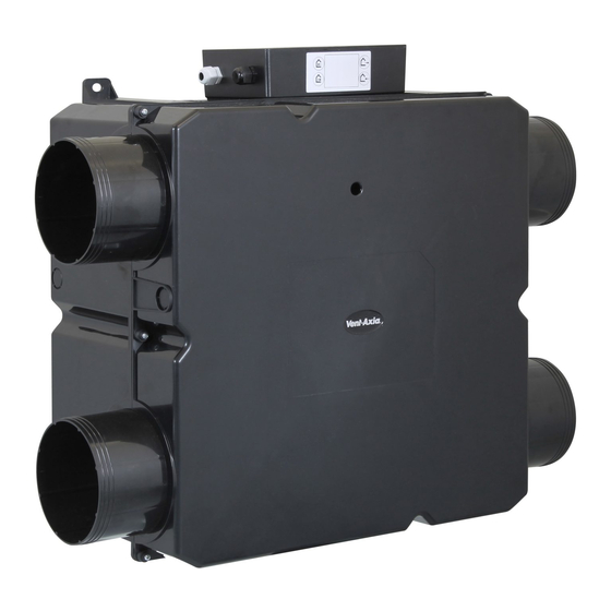
Product Description Product Description The Vent-Axia Integra Plus ECA Mechanical Ventilation/Heat Recovery (MVHR) is heat recovery unit designed for the energy efficient ventilation of houses and similar dwellings, conforming to the latest requirements of the Building Regulations document F 2010. - Page 6 Product Description Exploded View of Fan Unit Cover Heat recovery cell Motor assemblies Base assembly Ø150 Integra Plus ECA Dimensions Ø22 Integra Plus ECA MVHR Installation & Commissioning...
- Page 7 0% to 95% RH For all other technical details, please see the Product Catalogue or our website at www.vent-axia.com A wide range of sensors are available that can be used to switch the Integra Plus ECA from normal to boost...
-
Page 8: Installation Guidance
Installation Installation Guidance The following instructions are intended to help prevent potential hazards and installation should only be carried out by a qualified electrician and installer. NOTE: we advise installers to fix all mains and sensor wiring prior to fixing the MVHR unit in position. Before Installation of the Unit Inspect the Unit When taking delivery of the unit, check the items delivered against the enclosed delivery note. - Page 9 Installation Select Unit Orientation Fig 3a. Mounted on joists CONDENSATION DRAIN (THE UNIT SHOULD SLOPE DOWNWARDS BY 3°- 5° TOWARDS THE CONDENSATE DRAIN) Fig 3b. Ceiling mounted CONDENSATION DRAIN (THE UNIT SHOULD SLOPE DOWNWARDS BY 3°- 5° TOWARDS THE CONDENSATE DRAIN) Fig 3c.
- Page 10 Ceiling mounted:. Invert the unit with the Vent-Axia logo facing down and attach the unit securely to the rafters. For optimum performance, ensure the ductwork does not turn 90° directly off the spigots. The unit should, for optimum drainage, be tilted 3°- 5° towards the drain side.
-
Page 11: Electrical Installation
Installation Electrical Installation Connect Switches and Sensors Table 1: Mains Cable Connections Terminal No. Name Cable connection Description Mains Live Brown 220-240 V AC, 50 Hz input Mains Neutral Blue 220-240 V AC, 50 Hz input EARTH Mains Earth Yellow/Green Earth connector Switched Live 1 Black... - Page 12 Installation Connect the Power Supply WARNINGS 1. MAINS SUPPLY VOLTAGES (220-240 V AC) ARE PRESENT IN THIS EQUIPMENT, WHICH MAY CAUSE DEATH OR SERIOUS INJURY BY ELECTRIC SHOCK. ONLY A QUALIFIED ELECTRICIAN OR INSTALLER SHOULD CONNECT THE POWER SUPPLY TO THIS UNIT. 2.
- Page 13 Installation The remote lead is connected to the Remote Boost Switch Wires from Remote Boost Switch (factory fitted) Remote Lead colour wire colours LED Positive (RED) WHITE / ORANGE LED Negative (BLACK ORANGE WHITE / BLUE Boost Switch (BLACK) Boost Switch (BLACK) BLUE The unit can be switched to boost by applying 220-240V to the LS1 or LS2 inputs.
-
Page 14: Powering Up The Unit
Commissioning Powering Up the Unit Switching On Switch on the power at the mains supply isolator feeding the unit and the fan motors will start. Switching Off Turn the power off at the mains supply isolator switch. Commissioning Overview The instructions in this section are intended to provide configuration and operation information for setting up the equipment. -
Page 15: Modes Of Operation
If the LED on the Remote Boost switch flashes green, there is an error with the units Temperature sensor. The sensor is used by the frost protection system. If the unit was in Summer mode it will return to normal operation. Please contact the Vent-Axia Technical Support for assistance. -
Page 16: Maintenance
Check the condensate drain tube is secure and clear of debris. Clean if necessary. Fastenings Check that all unit and wall-mount fastenings are sufficiently tight and have not become loose. Re-tighten if necessary. Spares The following spares may be ordered from Vent-Axia: Integra Plus ECA Part No Description 431485... -
Page 17: Product Fiche
Product Fiche PRODUCT FICHE For Residential Ventilation Units (Complying Commission Delegated Regulation (EU) No 1254/2014 Name: Vent-Axia Vent-Axia Model ID (Stock Ref.) : Integra Plus ECA - 437666ECA Integra Plus ECA – 437666ECA SEC Class SEC Value ('Average') -32.34 -38.85 SEC Value ('Warm') -11.18... - Page 18 Notes:-...
- Page 19 Notes:- Integra Plus ECA MVHR Installation & Commissioning...
- Page 20 For details of guarantee outside the United Kingdom contact your local supplier. Vent-Axia guarantees its products for two years from date of purchase against faulty material or workmanship. In the event of any part being found to be defective, the product will be repaired, or at the Company’s option replaced, without charge, provided that the product: ...
Need help?
Do you have a question about the Integra Series and is the answer not in the manual?
Questions and answers