
Subscribe to Our Youtube Channel
Related Manuals for Vent-Axia Kinetic Plus E


Summary of Contents for Vent-Axia Kinetic Plus E
- Page 1 Kinetic Kinetic Plus E MVHR Installation & Commissioning Stock Ref. N° 449059 Kinetic Plus E PLEASE RETAIN THESE INSTRUCTIONS WITH THE PRODUCT. Copyright © 2009 Vent-Axia Limited. All rights reserved.
-
Page 2: Important Safety Information
Warnings & Safety Information IMPORTANT SAFETY INFORMATION 8. Young children should be supervised to PLEASE READ THESE ensure that they do not play with the INSTRUCTIONS CAREFULLY appliance. BEFORE COMMENCING INSTALLATION. INSTALLATION GUIDANCE 1. Do not install this product in areas where 1. -
Page 3: Table Of Contents
Installation Guidance ..............2 Declaration of Conformance Product Description Kinetic Plus E conform to the 2010 Building Regulations Kinetic Plus E ................. 4 (Part F - Means of Ventilation) installed performance of a ducted mechanical extract fan when installed in Technical Data ... -
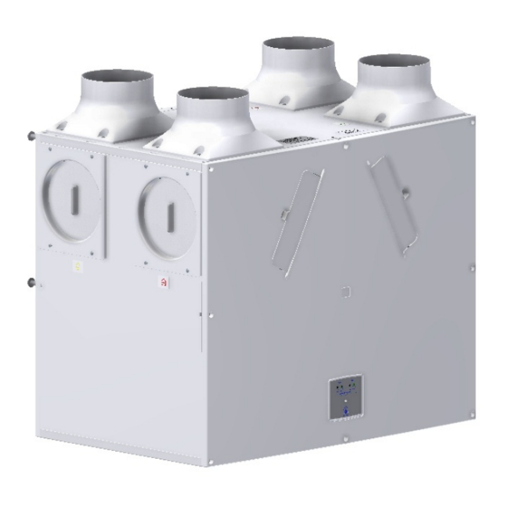
Page 4: Product Description
Figure 1: Kinetic Plus E (Front of Unit as supplied) A wide range of sensors is available that can be used to switch Kinetic Plus E from normal to boost speed and they are: ... -
Page 5: Technical Data
Installation Technical Data Performance Kinetic Plus E Airflow Maximum, FID, 500 m Normal factory set at minimum Boost factory set at minimum (For commissioning graphs see page 6) Sound levels (@ 3 m) 24 dB(A) (normal), 34 dB(A) (boost) Power... -
Page 6: Kinetic Plus E Performance Graph
Installation Figure 2: Kinetic Plus E Dimensions KINETIC Plus E Performance graph for Vertical and Horizontal Discharge Note: Graph show 2 typical system curves with total unit input power in Watts. Kinetic MVHR Installation & Commissioning... -
Page 7: Installation
Read and observe the safety notices listed in Warnings and Safety Information on page 2. Unit Installation The Kinetic Plus E unit is typically installed on a wall in a utility room, storage cupboard, roof void, or similar. The wall should have sufficient strength to support the unit. - Page 8 Installation Installing the Unit in the Opposite Orientation (LH Condensate) Installing the unit in the opposite orientation involves removing the front cover (and associated Control Unit Panel), and the rear cover (and associated Cable Inlet Plate), rotating the unit chassis and covers through 180 degrees and then re-attaching them.
- Page 9 Installation 4. Remove the 2 screws and detach the Control Panel and disconnect the mains lead. 5. Disconnect the connection looms. 6. Disconnect all the wiring looms from control panel. 7. Remove the 2 screws and detach the rear Cable Inlet Plate.
- Page 10 Installation Vertical Discharge Condensate Installation Note The 22 mm diameter condensate pipe is suitable for standard 22 mm plastic push-fit fittings and can be connected vertically underneath the unit or horizontally at the rear. To install the vertical discharge condensate: 1.
- Page 11 2. Remove the Black Cap from end of condensate stub at the front of the unit. 3. On the Kinetic Plus E drill a diameter 32mm hole using the indent provided in the moulding as a guide. The hole is a clearance hole for a diameter 22 mm pipe and so may vary a little from this guidance.
- Page 12 Installation 4. N.B. SEE “WALL MOUNTING” on pages 14 to 16 for information on marking out the wall for the position of the condensate drain and wall mounting brackets. Fit Vertical discharge 32mm waste pipe (fitted with 22 / 32mm reducer). Fit a ‘U’...
- Page 13 Note: Kinetic Plus E units have spigots suitable for either diameter 150 mm ducting (UK model) or for diameter 180 mm ducting (rest of EU model).
- Page 14 3. Mark the condensate and wall bracket positions using the template below. A paper copy can be obtained from Vent-Axia Technical Support. 4. Fit metal wall brackets (supplied) to the wall using appropriate fixings.
- Page 15 Installation Attaching the ducting: 1. Always use a short piece of flexible duct 100-150 mm long, extended to its full length when connecting to ductwork. 2. Securely connect this ducting to the spigots using worm-drive clips or cable ties. 3. Insulate any ducting passing through an unheated space to prevent any heat losses and surface condensation.
-
Page 16: Electrical Installation
EARTH Mains Earth Yellow/Green Earthing connector Switched Live 1 Black 220-240 V AC, 50 Hz input Switched Live 2 Black colour with 220-240 V AC, 50 Hz input white stripe CABLE FROM KINETIC PLUS E Kinetic MVHR Installation & Commissioning... - Page 17 Installation Connect the Power Supply WARNINGS 1. MAINS SUPPLY VOLTAGES (220-240 V AC) ARE PRESENT IN THIS EQUIPMENT WHICH MAY CAUSE DEATH OR SERIOUS INJURY BY ELECTRIC SHOCK. ONLY A QUALIFIED ELECTRICIAN OR INSTALLER SHOULD CONNECT THE POWER SUPPLY TO THIS UNIT. 2.
-
Page 18: Powering Up The Unit
Start Up Powering Up the Unit Switching On Switch on the power at the mains supply isolator feeding the unit and the fan motors will start. Switching Off Turn the power off at the mains supply isolator switch. Kinetic MVHR Installation & Commissioning... -
Page 19: Commissioning
Commissioning Overview The instructions in this section are intended to provide configuration and operation information for setting up the equipment. Follow good practice when commissioning the unit. Ensure that the system is installed according to the system designers intent incorporating any acoustic ducting, that all joints are air tight, ducting is well supported, bends are avoided close to vents, and that the vent valves are fully open at the start of the commissioning process. -
Page 20: Commissioning Control
Estimate the setting from the performance graph on page 6, measure the flow from the extract and supply grilles in the usual way. Adjust the potentiometers to suit. Figure 3: KINETIC PLUS E Controls Summer Mode The unit is equipped with a “Summer Mode” for use when the indoor temperature is higher than desired and the outdoor temperature is lower than the indoor temperature. - Page 21 Commissioning Button Operation Button Function Press once to activate Boost mode. Press once again to exit Boost mode. To activate Summer Mode press 3 times in less than three seconds, after a short pause the green LED will illuminate and the supply fan will stop. To exit Summer Mode press 3 times in less than three seconds, after a short pause the green LED will turn off and the supply fan will restart.
-
Page 22: Maintenance
Maintenance Heat recovery units require regular maintenance. The KINETIC PLUS E has been designed to facilitate access to enable maintenance to be carried out easily. WARNING THE FAN AND ANCILLARY CONTROL EQUIPMENT MUST BE ISOLATED FROM THE POWER SUPPLY DURING MAINTENANCE. -
Page 23: Spares
Maintenance Spares The following spares may be ordered from Vent-Axia: Kinetic Plus E Spares Part No Description 403732 Control Board 404943 T1 Temperature Sensor 403702 Filters, 2 per pack 403733 Heat Recovery Cell 403359 Extract Motor 403360 Supply Motor 444056 Spigot, one per pack Kinetic MVHR Installation &... - Page 24 Appendix PRODUCT FICHE For Residential Ventilation Units (Complying Commission Delegated Regulation (EU) No 1254/2014) Name: Vent‐Axia Model ID (Stock Ref.) : Kinetic Plus E ‐ 449059 SEC Class A+ SEC Value ('Average') ‐43.44 SEC Value ('Warm') ‐17.84 SEC Value ('Cold') ‐88.91 Label Required? (Yes/No=Out of scope) Yes Declared as: RVU or NRVU/UVU or BVU BVU Speed Drive Variable Speed Type HRS (Recuperative, Regenerative, None) Recuperative Thermal Eff: [ (%), NA(if none)] 93 Max. Flow Rate (m3/h) 417.6 Max. Power Input (W): (@Max.Flow Rate) 190 LWA: Sound Power Level (dB) ...
- Page 25 Vent-Axia guarantees its products for two years from date of purchase against faulty material or workmanship. In the event of any part being found to be defective, the product will be repaired, or at the Company’s option replaced, without charge, provided that the product:- ...
Need help?
Do you have a question about the Kinetic Plus E and is the answer not in the manual?
Questions and answers