Table of Contents
Advertisement
Quick Links
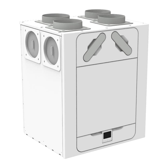
Sentinel Econiq
M & L MVHR
Installation and User Guide Instructions
Original instruction
PLEASE READ THESE INSTRUCTIONS CAREFULLY
BEFORE COMMENCING INSTALLATION OR OPERATION.
PLEASE REFER TO ACCOMPANYING DOCUMENTATION
FOR INFORMATION SPECIFIC TO YOUR UNIT.
PLEASE RETAIN THESE INSTRUCTIONS WITH THE
PRODUCT.
Warnings and Safety Information
Stock Ref. N°
499632 - Sentinel Econiq M
499638 - Sentinel Econiq MC
499639 - Sentinel Econiq MCP RH
499640 - Sentinel Econiq MCP LH
499641 - Sentinel Econiq L
499647 - Sentinel Econiq LC
499648 - Sentinel Econiq LCP RH
499649 - Sentinel Econiq LCP LH
Copyright © 2024 Vent-Axia. All rights reserved.
Advertisement
Table of Contents


Need help?
Do you have a question about the Sentinel Econiq M and is the answer not in the manual?
Questions and answers