Table of Contents
Advertisement
Quick Links
Industry Leader in RO Expertise and Membrane Applications since 1983™
Manual for
Operation & Maintenance
Of
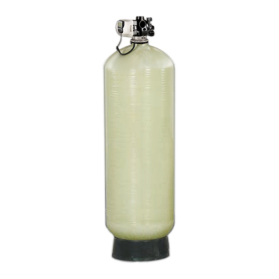
Carbon Filter with
Metered Valve
for Models:
W-G2162EM & W-G2472EM
Systems
Membranes & Chemicals
Filters
2325 Cousteau Ct. Vista, CA 92081 • (760) 727-3711 • FAX: (760) 727-4427
Internet: www.appliedmembranes.com • E-mail: sales@appliedmembranes.com
Document ID# OMC21-24EM
Revision: 06-26-2013
Advertisement
Table of Contents

Related Manuals for Applied Membranes W-G2162EM


Summary of Contents for Applied Membranes W-G2162EM
- Page 1 Manual for Operation & Maintenance Carbon Filter with Metered Valve for Models: W-G2162EM & W-G2472EM Systems Membranes & Chemicals Filters 2325 Cousteau Ct. Vista, CA 92081 • (760) 727-3711 • FAX: (760) 727-4427 Internet: www.appliedmembranes.com • E-mail: sales@appliedmembranes.com...
- Page 2 (Cancel request by pressing the “REGEN” button again.) Immediate Regeneration: Press and Hold the “REGEN” button for approximately 3 seconds. Regeneration will begin immediately. Request cannot be cancelled. Page 2 Copyright © 2012 Applied Membranes, Inc. All Rights Reserved.
-
Page 3: Table Of Contents
Drain Line Flow Control ..............................27 Meter Assembly Service Instructions ..........................27 Maintenance – Removal & Replacement of Carbon Media ..................... 28 Troubleshooting .................................. 29 Product Warranty ................................32 Page 3 Copyright © 2012 Applied Membranes, Inc. All Rights Reserved. -
Page 4: Design Basis & Specifications
1.5” * Filters are available with USA or European style plugs and voltages. W-G2162EM-US & W-G2472EM-US = 120V AC/60Hz with USA cord W-G2162EM-EU & W-G2472EM-EU = European 220V AC (EU plug is removable to convert into universal 220v cord) ** Backwash flow rate based on 25 psi pressure drop. -
Page 5: Loading The Media
Carbon × (-US or –EU) W-G2162EM 1 CF (100 lbs) N/A (0) 6 CF (165 lbs) W-G2472EM 1 CF (100 lbs) 1 CF (100 lbs) 8 CF( 220 lbs) Page 5 Copyright © 2012 Applied Membranes, Inc. All Rights Reserved. -
Page 6: Plumbing
Meter can be installed horizontally or vertically. *A longer cable (Part #V3221) is required for distances longer than 3” from the valve body. Page 6 Copyright © 2012 Applied Membranes, Inc. All Rights Reserved. -
Page 7: Operating Do's And Don'ts
DON’T: Permit oils or fats in feed water. Shut down system for extended periods. Exceed operating pressures or temperatures. Backwash filter with insufficient water flow. Page 7 Copyright © 2012 Applied Membranes, Inc. All Rights Reserved. -
Page 8: Initial Start-Up
Exposure to such hydrocarbons may cause the products to leak. Do not use the product(s) contained in this document on water supplies that contain hydrocarbons such as kerosene, benzene, gasoline, etc. Page 8 Copyright © 2012 Applied Membranes, Inc. All Rights Reserved. -
Page 9: Control Valve Operation & Service
No user serviceable parts are on the PC board, the motor, or the power adapter. The means of disconnection from the main power supply is by unplugging the power adapter from the wall. Page 9 Copyright © 2012 Applied Membranes, Inc. All Rights Reserved. -
Page 10: User Display
(Cancel request by pressing the “REGEN” button again.) Immediate Regeneration: Press and Hold the “REGEN” button for approximately 3 seconds. Regeneration will begin immediately. Request cannot be cancelled. Page 10 Copyright © 2012 Applied Membranes, Inc. All Rights Reserved. -
Page 11: General Warnings & Site Requirements
At the discretion of the installer, the end user can access all settings. To “lock out” access to programming settings, press the key sequence: ▲, NEXT, REGEN, ▼. When locked, the valve can be unlocked by pressing the same key sequence. Page 11 Copyright © 2012 Applied Membranes, Inc. All Rights Reserved. -
Page 12: Metered Backwash Filter Recommended Programming Overview
Time of day to backwash (time of projected non-use) & 5I Step 2CT FILTER Softener or Filter Setup Step 3CT Length of Backwash Step 4CT Length of Rinse Page 12 Copyright © 2012 Applied Membranes, Inc. All Rights Reserved. -
Page 13: Configuration Settings (Pre-Programmed To Factory Defaults)
Note: If the control valve enters into an error state during regeneration mode, the no hard water bypass will remain in its current state until the error is corrected and reset. Page 13 Copyright © 2012 Applied Membranes, Inc. All Rights Reserved. -
Page 14: Regeneration Cycle Time Settings (Pre-Programmed To Factory Defaults)
Adjust the length of the rinse from 1 to 95 minutes using the ▲and ▼ buttons. Recommended: 6 Press NEXT to go to exit Regeneration Cycle Times. Press REGEN to return to previous step. Page 14 Copyright © 2012 Applied Membranes, Inc. All Rights Reserved. -
Page 15: Installer Displays And Settings For Control Valve Options
Regeneration Time Minutes: Set the time of day for regeneration to occur by pressing ▲ or ▼. Press NEXT to go to the next step. Press NEXT to exit. Press REGEN to go to the previous step. Page 15 Copyright © 2012 Applied Membranes, Inc. All Rights Reserved. - Page 16 Regeneration Time Minutes: Set the time of day for regeneration to occur by pressing ▲ or ▼. Press NEXT to go to the next step. Press NEXT to exit Installer Displays and Settings. Page 16 Copyright © 2012 Applied Membranes, Inc. All Rights Reserved.
-
Page 17: Diagnostics
Press NEXT to go to next step. Press REGEN to return to previous step. Step 5D Display shows the total number of regeneration cycles since start up. Press NEXT to exit Diagnostics. Press REGEN to return to previous step. Page 17 Copyright © 2012 Applied Membranes, Inc. All Rights Reserved. -
Page 18: Control Valve Drawings And Components
Installation and Service Manual – Metered Carbon Filter Control Valve Drawings and Components CV1.5 Overview Drawings Page 18 Copyright © 2012 Applied Membranes, Inc. All Rights Reserved. -
Page 19: Cv1.5 Drive Cap Assembly, Downflow Piston, Regenerate Piston & Spacer Stack Assembly
Back Plate Back Plate V3419 O-Ring, 347 V3641 O-Ring,225 V3950-01 CV1.5 NPT Valve Body, w/ V3468 not shown V3468 Test Port Plug, ¼” NPT D1300 Top Baffle Diffuser, 1.5/50MM Page 19 Copyright © 2012 Applied Membranes, Inc. All Rights Reserved. -
Page 20: Cv1.5 Injector Valve Body, Refill Flow Control And Injector Plug
*V3968 contains one D1240o O-Ring (111) and two V3155 O-Ring (112) **V3969 contains one V3638 O-Ring (113) and two V3157 O-Ring (1155) *** Ctonatins a V3182 0.5 gpm flow control Page 20 Copyright © 2012 Applied Membranes, Inc. All Rights Reserved. -
Page 21: Cv1.5 Drain Line Flow Controls
DLFC Flange Outlet, FNPT V3646 DLFC Flange Inlet, MNPT V3652 Bolt, Hex S/S HCS 5/16-18x3/4 V3441 O-Ring, 226 V3190-250 DLFC Washer, Center, 25 GPM V3162-100 DLFC Washer, Side, 10 GPM V3190-250 V3162-100 Page 21 Copyright © 2012 Applied Membranes, Inc. All Rights Reserved. -
Page 22: Meter Assembly
This water meter should nto be used as the primary monitoring device for critical or health effect applications. Operating pressures: 20 psi minimum/ 125 psi maximum. Operating temperatures: 40°F Minimum/ 110°F Maximum Page 22 Copyright © 2012 Applied Membranes, Inc. All Rights Reserved. -
Page 23: Cv1.5 Flow Diagram, Service
Installation and Service Manual – Metered Carbon Filter CV1.5 Flow Diagram, Service CV1.5 Flow Diagram, Backwash Page 23 Copyright © 2012 Applied Membranes, Inc. All Rights Reserved. -
Page 24: Cv1.5 Flow Diagram, Rinse
Although no tools are necessary to assemble or disassemble the valve, the CV1 wrench (shown below in various positions on the valve) may be purchased separately to aid in assembly or disassembly of the control valve. Figure 1 Page 24 Copyright © 2012 Applied Membranes, Inc. All Rights Reserved. -
Page 25: Control Valve Service Instructions
(black wire) and plug back in. This resets the electronics and establishes the service piston position. The display should flash all wording, then flash the software version and then reset the valve to the service position. Page 25 Copyright © 2012 Applied Membranes, Inc. All Rights Reserved. -
Page 26: Drive Cap Assembly
The display should flash all wording, then flash the software version and then reset the valve to the service position. Page 26 Copyright © 2012 Applied Membranes, Inc. All Rights Reserved. -
Page 27: Spacer Stack Assembly
Reinstall the meter retaining clip. Open the bypass for the system slowly to bring back into service and check to be sure you have no water leaks. Page 27 Copyright © 2012 Applied Membranes, Inc. All Rights Reserved. -
Page 28: Maintenance - Removal & Replacement Of Carbon Media
When all material is out of tank wash it with clean water. Note: Dispose of the carbon & underbedding by local procedures or laws. 12. Replace media as per media loading instructions. 13. Perform start-up procedure. Page 28 Copyright © 2012 Applied Membranes, Inc. All Rights Reserved. -
Page 29: Troubleshooting
Restricted/Stalled turbine Remove meter and check for rotation or foreign material Defective meter Replace meter Defective PC board Replace PC board Page 29 Copyright © 2012 Applied Membranes, Inc. All Rights Reserved. - Page 30 Press and hold NEXT and REGEN buttons for 3 seconds or unplug power source jack (black wire) and plug back in to reset the valve. Page 30 Copyright © 2012 Applied Membranes, Inc. All Rights Reserved.
- Page 31 (black wire) and plug home position do not interface back in to reset the valve. Page 31 Copyright © 2012 Applied Membranes, Inc. All Rights Reserved.
-
Page 32: Product Warranty
Product Warranty SELLER hereby warrants to CUSTOMER that the goods herein described will be free from any liens or encumbrances, that good title to said goods will be conveyed to CUSTOMER by sale of same. SELLER warrants materials of its own manufacture against defects in material and workmanship under normal conditions of usage and service for one year from whichever of the following events occurs first: ...
Need help?
Do you have a question about the W-G2162EM and is the answer not in the manual?
Questions and answers