Table of Contents
Troubleshooting

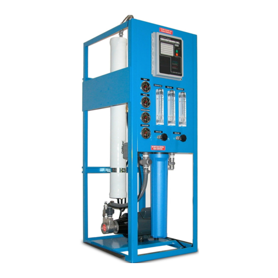
Related Manuals for Applied Membranes L Series


Summary of Contents for Applied Membranes L Series
- Page 1 Manual for Operation & Maintenance L Series Reverse Osmosis Systems With S100 Controller Industry Leader in RO Expertise and Membrane Applications Since 1983™ 2325 Cousteau Ct. • Vista, CA 92081, USA • www.appliedmembranes.com...
-
Page 2: Table Of Contents
Installation and Service Manual – L Series Reverse Osmosis System Table of Contents Design Basis & System Design Specifications ........................3 Design Notes ..................................4 General Information and Safety ............................5 System Installation ................................5 ... -
Page 3: Design Basis & System Design Specifications
Installation and Service Manual – L Series Reverse Osmosis System Design Basis & System Design Specifications Design Conditions Limits* Line Sizes (Inches) Pump model and HP Full Load Permeate Flow Conc. Design Max. Design Motor Design Max. Amps Model Pump Model No. -
Page 4: Design Notes
• Feed water turbidity: Less than 1 NTU; Feed water silt density index (SDI): 3 maximum. If exceeded, pretreatment with media filter recommended. All pretreatment equipment and SDI test kits are available from Applied Membranes. • Capacity Basis: 24 hrs/day Design Notes 1. -
Page 5: General Information And Safety
Installation and Service Manual – L Series Reverse Osmosis System General Information and Safety DISCLAIMER: SERVICE WARNING: The information contained in this document is subject to To prevent electrical shock, disconnect power to the system change without notice. prior to servicing. -
Page 6: Plumbing
Installation and Service Manual – L Series Reverse Osmosis System Plumbing Refer to the P&ID on page 31 for further information. Note: All plumbing is to be done in accordance with state and local codes. Caution: This unit produces high quality water which can cause corrosion or leaching of the plumbing following the system. -
Page 7: Product Water Storage Tank Level Float Installation
Installation and Service Manual – L Series Reverse Osmosis System Product Water Storage Tank Level Float Installation Note: Please read all steps of installation instructions before beginning. Note: If using a repressurization pump, a third float should be used to turn the pump off when the tank is empty. -
Page 8: Electrical Connections
Installation and Service Manual – L Series Reverse Osmosis System Electrical Connections All electrical connections should be done by a qualified electrician and are to be in accordance with state and local codes. Note: For Full Load Amps and Fuses Information, please see system design specifications on pages 3-4. -
Page 9: Series S100 Ro System Controller Installation And Setup
Series S100 RO System Controller Installation and Setup Introduction The Applied Membranes Inc. Series 100 controller is a state of the art control system for commercial and industrial reverse osmosis systems. The Series 100 is a microprocessor controlled system that can monitor pressure and level switches. - Page 10 Installation and Service Manual – L Series Reverse Osmosis System Switch Inputs Switch inputs are connected to P2. The connections for these inputs are not polarity sensitive and can be connected to either terminal. The switch inputs should be dry contact closures only. CAUTION: Applying voltage to these terminals will damage the controller.
- Page 11 Installation and Service Manual – L Series Reverse Osmosis System Systems and Components Membranes, Filters, Chemicals 2325 Cousteau Ct., Vista, CA 92081 USA • www.appliedmembranes.com • E-mail: sales@appliedmembranes.com Copyright © 2008 Applied Membranes, Inc. All Rights Reserved. Page 11...
- Page 12 Installation and Service Manual – L Series Reverse Osmosis System Systems and Components Membranes, Filters, Chemicals 2325 Cousteau Ct., Vista, CA 92081 USA • www.appliedmembranes.com • E-mail: sales@appliedmembranes.com Copyright © 2008 Applied Membranes, Inc. All Rights Reserved. Page 12...
-
Page 13: System Operation
Installation and Service Manual – L Series Reverse Osmosis System System Operation Series S100 RO System Controller Operation General Operation The unit has 2 modes of operation, a standby mode and an operating mode. In the standby mode, the unit is effectively off. - Page 14 Installation and Service Manual – L Series Reverse Osmosis System Pressure Fault If the pressure fault input is active for 2 seconds, a pressure fault condition will occur. This will cause the controller to shut down. PF will show on the water quality display and the status lamp will flash red. To clear the pressure fault, press the power key twice.
-
Page 15: Initial System Start-Up
Installation and Service Manual – L Series Reverse Osmosis System Water Quality Setpoint The water quality setpoint can be adjusted from 0-999. If set to 999, the water quality lamp will always remain green. To set the water quality setpoint, press the Setpoint key. The display will alternate between the setpoint and SP. Use a small screwdriver to adjust the SP adjustment to the desired setpoint value. -
Page 16: Operating Do's & Don'ts
Installation and Service Manual – L Series Reverse Osmosis System 10. Adjust the Throttle Valve (CV-1) to get the specified permeate flow (if applicable). 11. Adjust the Control Valve (CV-2) and Recycle Valve (CV-3) until the specified permeate flow and recycle flow are obtained. It may be necessary to readjust the Throttle Valve (CV-1). -
Page 17: System Automation
Installation and Service Manual – L Series Reverse Osmosis System System Automation The system will automatically turn on when the water level in the permeate tank reaches the mid level float, and turn off when the water meets the high level float. -
Page 18: Data Log
Installation and Service Manual – L Series Reverse Osmosis System Data Log Data for Each Date/Time Date/Time Temperature (Deg. F) Feed Pressures (PSI) Feed System Media Filter IN Media Filter* OUT Cartridge Filter* IN Cartridge Filter OUT Flow (GPM) Permeate** (P) -
Page 19: System Operation Temperature
Installation and Service Manual – L Series Reverse Osmosis System System Operation Temperature The water temperature is one of the key factors in the performance of the reverse osmosis membrane element. A higher temperature will result in more product flow and a lower temperature will result in less product flow. -
Page 20: System Controller Troubleshooting - Series S100
Installation and Service Manual – L Series Reverse Osmosis System System Controller Troubleshooting – Series S100 Caution: Hazardous voltages are present when power is applied to the controller. Pressing the Power key DOES NOT remove these voltages. The power must be disconnected from the power source. When connecting or disconnecting any wiring to the unit, be sure the power is turned off at the disconnect or breaker. - Page 21 Installation and Service Manual – L Series Reverse Osmosis System Pump is working below its Low motor RPM Check your motor to make sure it is working capacity properly and that it is wired for the voltage (continued from previous page)
-
Page 22: System Maintenance
Installation and Service Manual – L Series Reverse Osmosis System System Maintenance Maintain proper operating conditions. (See section: “Design Basis” on pages 3-4) Sediment Pre-Filter Cartridge When to Change Sediment Prefilter Cartridge Sediment cartridge Filters should be changed regularly to maintain proper pump pressure and flow. -
Page 23: Membrane Replacement
Installation and Service Manual – L Series Reverse Osmosis System Cleaning Sequence Whether the system needs acid or alkaline cleaning will depend on the type of foulant suspected. We recommend acid cleaning be performed first, even when alkaline cleaning is desired. If system performance recovers with acid cleaning, then alkaline cleaning is not necessary. -
Page 24: Low Pressure Switch Adjustment
Installation and Service Manual – L Series Reverse Osmosis System Low Pressure Switch Adjustment Adjust in the proper sequence: 1. Range: Turn nut down (clockwise) for higher cut-in pressure, or up (counterclockwise) for lower cut-in. 2. Differential: Turn nut down (clockwise) for higher-cut-out pressure, or up (counterclockwise) for lower cut-out. - Page 25 Installation and Service Manual – L Series Reverse Osmosis System Mechanical Seal Changeout (refer to figures above) This procedure is best completed with the pump held in a vertical position, motor down. First, complete “Disassembly” instructions 1 through 5 under “Impeller Stack Changeout.” (see previous page) 6.
-
Page 26: Shut-Down And Storage
Installation and Service Manual – L Series Reverse Osmosis System Shut-Down and Storage Caution: Handle all chemicals with care. Wear protective clothing and eye protection. Membrane Storage (outside of RO system) To prevent bacterial growth and help maintain flux, it is recommended that elements be immersed in a solution 20.0 percent, by weight, AM-225 and 1.0 percent by weight AM-88. -
Page 27: System Layout And Component Identification
Installation and Service Manual – L Series Reverse Osmosis System System Layout and Component Identification Component Identification- Standard Features up to L-64A System Model Numbers (followed by 3 digit voltage code) Component Identification by P&ID from P&ID on Page 31... - Page 28 Installation and Service Manual – L Series Reverse Osmosis System (Continued) Component Identification- up to L-64A System Model Numbers (followed by 3 digit voltage code) Component Identification by P&ID from P&ID on Page 31 L-12521A L-125A L-225A L-14A L-24A L-34A...
-
Page 29: Component Identification- Standard Features For L-74A
Installation and Service Manual – L Series Reverse Osmosis System Component Identification- Standard Features for L-74A+ System Model Numbers (followed by 3 digit voltage code) Component Identification by P&ID L-74A L-84A L-94A L-104A L-114A L-124A from P&ID on Page 31 Part No. -
Page 30: General Arrangement Of Systems With Procon Pump
Installation and Service Manual – L Series Reverse Osmosis System General Arrangement of Systems with Procon Pump General Arrangement of Systems with Sta-Rite Pump Systems and Components Membranes, Filters, Chemicals 2325 Cousteau Ct., Vista, CA 92081 USA • www.appliedmembranes.com • E-mail: sales@appliedmembranes.com Copyright ©... -
Page 31: Parts & Instrumentation Drawing (P&Id)
Installation and Service Manual – L Series Reverse Osmosis System Parts & Instrumentation Drawing (P&ID) Systems and Components Membranes, Filters, Chemicals 2325 Cousteau Ct., Vista, CA 92081 USA • www.appliedmembranes.com • E-mail: sales@appliedmembranes.com Copyright © 2008 Applied Membranes, Inc. All Rights Reserved. -
Page 32: Replacement Parts And Consumables
Installation and Service Manual – L Series Reverse Osmosis System Replacement Parts and Consumables Replacement Filters, RO Membranes, Membrane Housing Pressure Vessels and Components Model No. Description H-F2005CF 5 Micron Sediment Pre-Filter Cartridge C-C2520-A11 Cleaning Cartridge – Acid for Scale Removal C-C2520-A22 Cleaning Cartridge –... -
Page 33: Optional Equipment & Add-Ons
Installation and Service Manual – L Series Reverse Osmosis System Pump Replacement Parts (for systems with Sta-Rite pump), For L-14A, L-24A: 50Hz Only; L-34A, L-44A, L-54A, L-64A, L-84A, L-94A, L-104A, L-114A, L-124A Description Qty. Replacement Part # Motor - 230 Volt, 1 Phase... - Page 34 Installation and Service Manual – L Series Reverse Osmosis System – System Options Information Front Panel Controls and Indicator Feature Description DISPLAY Shows status of the system. ALARM LAMP Flashes when fault causes an RO system shut-down. ON steady when a set-point is exceeded that does not cause an RO system shut-down.
- Page 35 Installation and Service Manual – L Series Reverse Osmosis System – System Options Information Installation – Electrical Connections All electrical connections should to be done by a qualified electrician and are to be in accordance with state and local codes.
-
Page 36: Product Warranty
Product Warranty SELLER hereby warrants to CUSTOMER that the goods herein described will be free from any liens or encumbrances, that good title to said goods will be conveyed to CUSTOMER by sale of same. SELLER warrants materials of its own manufacture against defects in material and workmanship under normal conditions of usage and service for one year from whichever of the following events occurs first: ...
Need help?
Do you have a question about the L Series and is the answer not in the manual?
Questions and answers