Graco Reactor A-25 Repair Parts
Plural-component sprayer
Hide thumbs
Also See for Reactor A-25:
- Instructions manual (64 pages) ,
- Repair parts (58 pages) ,
- Operation (40 pages)
Table of Contents
Advertisement
Quick Links
Repair-Parts
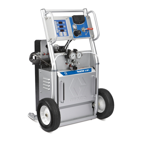
Air operated, electrically heated, plural component proportioner
A-25: For spraying or dispensing 1:1 ratio polyurethane foam formulations and other
1:1 fast setting materials.
A-XP1: For spraying or dispensing 1:1 ratio polyurea formulations and other 1:1 fast
setting materials.
Not for use in explosive atmosphere or hazardous locations.
This model is field-configurable to the following supply voltages:
200-240 VAC, 1 Phase
200-240 VAC, 3 Phase
350-415 VAC, 3 Phase
A-25:
2000 psi (14 MPa, 138 bar) Maximum Fluid Working Pressure
80 psi (550 kPa, 5.5 bar) Maximum Air Working Pressure
A-XP1:
3500 psi (24 MPa, 241 bar) Maximum Fluid Working Pressure
100psi (689 kPa, 6.9 bar) Maximum Air Working Pressure
Important Safety Instructions
Read all warnings and instructions in this
manual. Save these instructions.
See page 3 for model information,
including maximum working pressure and approvals.
3A1570L
EN
ti16811b
Advertisement
Table of Contents

Related Manuals for Graco Reactor A-25


Summary of Contents for Graco Reactor A-25
- Page 1 Repair-Parts 3A1570L Air operated, electrically heated, plural component proportioner A-25: For spraying or dispensing 1:1 ratio polyurethane foam formulations and other 1:1 fast setting materials. A-XP1: For spraying or dispensing 1:1 ratio polyurea formulations and other 1:1 fast setting materials. Not for use in explosive atmosphere or hazardous locations.
-
Page 2: Table Of Contents
... . 12 Reactor A-25/A-XP1 Wiring Schematic ..52 E05: Control board over temperature ..13 A-25 . -
Page 3: Proportioner Models
Proportioner Models Proportioner Models All proportioners can be configured to operate on 350-415V (4 wire), 200-240V (3 wire), or 200-240V 1Ø. Includes: Maximum Fluid Working Maximum Air Working Pressure Set Pressure DataTrak Part psi (MPa, bar) psi (kPa, bar) (cycle count only) Wheels Approvals 262572... -
Page 4: Related Manuals
Related Manuals Manuals are available at www.graco.com. Component manuals in English: Manual Description 3A1569 Reactor A-25 Proportioner, Operation 309577 Proportioning Pump, Repair-Parts 309815 Feed Pump Kit, Instructions-Parts 309827 Feed Pump Air Supply KIt, Instructions-Parts 309852 Circulation and Return Tube Kit, Instruc-... -
Page 5: Warnings
Warnings Warnings The following warnings are for the setup, use, grounding, maintenance, and repair of this equipment. The exclama- tion point symbol alerts you to a general warning and the hazard symbols refer to procedure-specific risks. When these symbols appear in the body of this manual, refer back to these Warnings. Product-specific hazard symbols and warnings not covered in this section may appear throughout the body of this manual where applicable. - Page 6 Warnings WARNING FIRE AND EXPLOSION HAZARD Flammable fumes, such as solvent and paint fumes, in work area can ignite or explode. To help pre- vent fire and explosion: • Use equipment only in well ventilated area. • Eliminate all ignition sources; such as pilot lights, cigarettes, portable electric lamps, and plastic drop cloths (potential static arc).
- Page 7 Warnings WARNING EQUIPMENT MISUSE HAZARD Misuse can cause death or serious injury. • Do not operate the unit when fatigued or under the influence of drugs or alcohol. • Do not exceed the maximum working pressure or temperature rating of the lowest rated system component.
-
Page 8: Important Two-Component Material Information
Important Isocyanate (ISO) Information Important Isocyanate (ISO) Information Isocyanates (ISO) are catalysts used in two-component materials. Isocyanate Conditions Spraying or dispensing fluids that contain isocyanates creates potentially harmful mists, vapors, and atomized particulates. • Read and understand the fluid manufacturer’s warnings and Safety Data Sheet (SDS) to know specific haz- ards and precautions related to isocyanates. -
Page 9: Material Self-Ignition
Important Isocyanate (ISO) Information Material Self-ignition Foam Resins with 245 fa Blowing Agents Some foam blowing agents will froth at temperatures above 90°F (33°C) when not under pressure, especially if agitated. To reduce frothing, minimize preheating in a circulation Some materials may become self-igniting if applied too thick. system. - Page 10 Important Isocyanate (ISO) Information DataTrak Diagnostic Codes DataTrak can diagnose several problems with the To acknowledge the diagnosis and return to the normal pump. When the monitor detects a problem, the LED will operating screen, press once to wake up the dis- flash and a diagnostic code will appear on the display.
- Page 11 Important Isocyanate (ISO) Information E01: High fluid temperature Causes of E01 Errors between temperature control module and thermo- couples A and B (361) or FTS (21) [depending on • Thermocouple A or B (361) senses a fluid tempera- which zone is displaying E01]. See Table 2, page ture above 230°F (110°C).
-
Page 12: E02: High Zone Current
Important Isocyanate (ISO) Information bly Modules, page 28. b. Perform Transformer Primary Check and Transformer Secondary Check, starting on d. If the swapped module does not fix the problem, page 34. the power module is not the cause. When a no current error occurs, the LED on this specific 8. -
Page 13: E05: Control Board Over Temperature
Important Isocyanate (ISO) Information E05: Control board over Communication Diagnostic temperature Codes Each module has an on-board temperature sensor. Heat is turned off if module temperature exceeds 185°F E30: Momentary loss of (85°C) within the heater module. communication 1. Check that fan above electrical cabinet is operating. Communications between the display and the motor control board or the temperature control module have 2. -
Page 14: Before Beginning Repair
Before Beginning Repair Before Beginning Repair 5. Close gun fluid inlet valves A and B. Repairing this equipment requires access to parts that may cause electric shock or other serious injury if work is not performed properly. Electrical trouble- shooting must be done by a qualified electrician. Be ti2421a sure to shut off all power to equipment and lock out power at the source before repairing. -
Page 15: Park
Park Park Flushing Park the pumps at the end of the day to cycle compo- nent A pump to home position, submerging displace- ment rod. Flush equipment only in a well-ventilated area. Do not spray flammable fluids. Do not turn on heaters while 1. -
Page 16: Troubleshooting
Troubleshooting Troubleshooting Problems Before performing any troubleshooting procedures: 1. Relieve pressure, page 14. Try the recommended solutions in the order given for each problem, to avoid unnecessary repairs. Also, determine that all circuit breakers, switches, and con- trols are properly set and wiring is correct before assum- 2. - Page 17 Troubleshooting PROBLEM CAUSE SOLUTION Fluid pressure low or dropping Air supply pressure low when spray- Increase inlet air pressure Increase air compressor size to meet flow requirements Remove airline quick disconnects Use 3/8 in. (0.95 cm) ID or larger air supply hose.
- Page 18 Troubleshooting PROBLEM CAUSE SOLUTION Fluid pressures not balanced Fluid viscosities not equal Adjust A and B temperature settings between A and B side to balance viscosity. Sometimes nor- mal if pressure offset is below 200 psi (14 bar) Preheat material in drums by recircu- lating;...
- Page 19 Troubleshooting Problem Cause Solution Low voltage. Ensure input voltage is within specifi- cations, page 37. Poor display connection. Check cable connections, page 37. Replace damaged cable. Erratic display; display turns on and off. Display cable damaged or corroded. Clean connections; replace cable if is damaged.
- Page 20 Troubleshooting Heater PROBLEM CAUSE SOLUTION Heat turned off. Press zone Primary heater(s) does not heat. keys. Temperature control alarm. Check temperature display for diag- nostic code, page 10. Signal failure from thermocouple. See E04: Fluid Temperature Sen- sor (FTS) or thermocouple discon- nected, page 12.
- Page 21 Troubleshooting Hose Heat System PROBLEM CAUSE SOLUTION Ambient temperature is too cold. Use auxiliary hose heat system. FTS failed or not installed correctly. Check FTS, page 12. Hose heats but heats slower than usual or it does not reach tempera- Low supply voltage.
- Page 22 Troubleshooting PROBLEM CAUSE SOLUTION Faulty thermocouple connections. Verify that all FTS connections are snug and that pins of connectors are clean. Examine connection of ther- mocouples to long green plug on heater control board. Unplug and Erratic hose temperature. re-plug thermocouple wires, cleaning off any debris.
-
Page 23: Repair
Repair Repair 6. Shut off inlet air ball valve (G) 7. Remove screws (13, 15) and pump covers (63). Unless otherwise noted, all repair procedures must be completed with incoming power switched OFF and locked out at the source. Any electrical repair or troubleshooting required beyond the scope of this manual must be performed by a qualified electrician. -
Page 24: Connect Pump
Repair 11. Push retaining wire clip (307) up. Push retaining pin 5. For Iso A pump only: (306) out. a. Install two pipe plugs (324). b. Reconnect two tubing lines (N) from ISO Pump Lube reservoir. Flush and refill reservoir with TSL 206995. -
Page 25: Remove Air Motor
Repair Remove Air Motor 6. Lay air motor on a clean flat work space. Place a wrench on the tie rod flats (309) and hold one of other tie rods with your hand to keep the air motor 1. Press in tube fitting ferrules and pull out tubing (65) (308) in place. -
Page 26: Recirculation / Over Pressure Relief Block
Repair Recirculation / Over Pressure Air Inlet Filter / Water Separator Relief Block (Auto Drain) Valves can be serviced with the block on the machine Air Filter Element Removal (see page 47 for parts view). For thorough cleaning, remove the block assembly as follows. 1. -
Page 27: Temperature Control Module
Repair Temperature Control Module Table 2: Temperature Control Module Connections Connector Description DATA (A) Data reporting HOSE T/C P; FTS (purple) HOSE T/C R; FTS (red) HOSE T/C S; FTS (silver (unshielded bare wire)) HEATER T/C B, Y; ti17997a Thermocouple (yellow) SENSOR (B) HEATER T/C B, R;... - Page 28 Repair Test SCR Circuit Replacing Temperature Control Assembly Modules 1. Test the SCR circuit in the on position: a. Make sure everything is connected, including the hose. NOTICE b. Turn main power ON Before handling assembly, put on static conductive wrist strap to protect against static discharge which c.
-
Page 29: Primary Heater
Repair Primary Heater Line Voltage The primary heaters output their rated wattage at 230 Vac. Low line voltage will reduce power available and the heaters will not perform at full capability. Read Warnings on page 5. Wait for heater to cool before repairing. - Page 30 Repair Torque to 120 ft-lbs (163 N•m). Torque to 23 ft-lbs (31 N•m). Torque to 40 ft-lbs (54 N•m). ti17998a Apply 110009 thermal heatsink compound. Apply sealant and PTFE tape to all non swiveling and threads without o-rings. Apply lubricant to o-rings. Orient rupture disc housing (369) with exhaust hole pointing towards the bottom of the heater.
- Page 31 Repair Thermocouple Read Warnings on page 5. Wait for heater to cool before repairing. a. Remove protective tape from thermocouple tip (T). 1. Turn main power OFF . Disconnect power supply. b. Apply PTFE tape and thread sealant to male threads and tighten thermocouple housing (H) 2.
-
Page 32: Heated Hose
Repair Overtemperature Switch 4. For Series A only: Disconnect hose connector (D) at Reactor. Read Warnings on page 5. Wait for heater to cool before repairing. 1. Turn main power OFF . Disconnect power supply. 5. Using an ohmmeter, check between the two 2. -
Page 33: Fluid Temperature Sensor (Fts)
Repair Fluid Temperature Sensor (FTS) 4. If FTS fails any test, replace FTS. 5. Disconnect air hoses (C, L), and electrical connec- Test/Removal tors (D). 6. Disconnect FTS from whip hose (W) and fluid hoses 1. Turn main power OFF . - Page 34 Repair Transformer Primary Check 3. To verify transformer voltage, turn on hose zone. Measure voltage from 178CB-2 to HPOD-1; see Reactor A-25/A-XP1 Wiring Schematic, page 52. 1. Turn main power OFF Model Secondary Voltage 2. Locate the two smaller (10 AWG) wires coming out 310 ft.
- Page 35 Repair Replace Circuit Breaker Module 1. Turn main power OFF . Disconnect power supply. Turn circuit breakers on to test. 2. Relieve pressure, page 14. 3. Using an ohmmeter, check for continuity across cir- cuit breaker (top to bottom). If no continuity, trip breaker, reset, and retest.
-
Page 36: Pump Lubrication System
Repair Pump Lubrication System Check the condition of the ISO pump lubricant daily. Change the lubricant if it becomes a gel, its color dark- ens, or it becomes diluted with isocyanate. Gel formation is due to moisture absorption by the pump lubricant. -
Page 37: Fluid Inlet Strainer Screen
2. Relieve pressure, page 14. ing out any isocyanate residue at the start of dispensing operations. 3. Refer to Reactor A-25/A-XP1 Wiring Schematic, page 52. 1. Close the fluid inlet valve at the pump inlet and shut 4. Put on static conductive wrist strap. - Page 38 Repair ti18026a Detail of Membrane Switches and Temperature Display Board 102a Temperature Display 102b 102c ti18003a . 15. Display Module 3A1570L...
-
Page 39: Replace Datatrak Battery Or Fuse
Use only the following approved replacement bat- Replace Fuse teries. Use of an unapproved battery will void Graco’s warranty and FM and Ex approvals. 1. Remove the screw, metal strap, and plastic holder. • Ultralife lithium # U9VL 2. -
Page 40: Accessories
Accessories Accessories Feed Pump Kits P2 Spray Gun Pumps, hoses, and mounting hardware to supply fluids to Probler P2 Gun available in round or flat pattern. See 313213. Reactor. Includes 246483 Air Supply Kit. See 309815. Y-Strainer Screen 246483 Air Supply Kit Replacement strainer screen for fluid Y-strainer;... -
Page 41: Parts
Parts Parts 262572, Bare Reactor A-25 / 24Y164, A-XP1 Bare 262614, Reactor A-25 with DataTrak and Wheels / 24Y165, A-XP1 with DataTrak and Wheels 14 (x4) 56 (x4) 100 (x4) 9 (x4) 91, 92 90 (x6) 3A1570L... - Page 42 Parts 25 (x2) 13 (x2) 9 (x4) 13 (x2) ti18024a Torque pump locking nuts to 66-74 ft-lbs (90-100 N•m). Apply anaerobic polyacrylate pipe sealant to all non-swiveling pipe threads. Torque tube ends to 212-265 in-lbs (24-30 N•m). Connect ground wire (94) from motor lug to ground lug in cabinet. For Series A only 3A1570L...
- Page 43 Parts 13 (x4) 13 (x4) ti18007a 262572, Bare Reactor A-25 / 24Y164, Bare Reactor A-XP1 262614, Reactor A-25 with DataTrak and Wheels / 24Y165, Reactor A-XP1 with DataTrak and Wheels Ref. Part Description Qty. 262575 PANEL (A-25), control; see page 45...
- Page 44 Parts 114182 SCREW, mach, hex flange; M6 x 1 TUBE, polyurethane, rnd, black; 5.12 ft (1.56 m); see page 50 117623 NUT, cap, 3/8-16 66 INSERT, control panel 106084 SCREW, mach, pan hd; M5 x 0.8 67† 24B563 KIT, DataTrak 117682 BUSHING, strain relief 68†...
-
Page 45: Control Panel, A-25: 262575, A-Xp1: 24Y176
Parts Control Panel, A-25: 262575, A-XP1: 24Y176 Apply sealant to all non swiveling pipe threads. Attach ground wire from harness (116) between connector on harness (106) and display cover (105). Attach harness (106) to J13 on board (102). Attach harness (119) to J1 on board (102). ti18002a 114362 VALVE, ball, air... -
Page 46: Temperature Control
Parts Temperature Control Wheel Kit, 262695 To B Heater Module To A Heater Module To Hose ti18006a Heater Module Ref. Part Description 191† 16H182 AXLE, wheel 192† 111841 WASHER, plain 5/8 Ref. Part Description Qty. 193† 191824 WASHER, space 151 16G925 PANEL, pod, mounting 194†... -
Page 47: Fluid Manifold
Parts Fluid Manifold Fluid Inlet Kit, 234366 A-25: 262577 A-XP1: 24Y177 208b 208a ti18027a Assemble ball valves in orientation shown. Apply anaerobic polyacrylate pipe sealant to all NPT connections. Ref. Part Description Qty. ti8459a 160327 UNION, adapter, 90°; 3/4 npt(m) x 3/4-14 npt(f) Apply sealant and torque to 250 in-lbs (28 N•m). -
Page 48: A-Xp1: 10 Kw Dual Zone Heater, 24Y163 A-25: 6 Kw Dual Zone Heater, 24J788
Parts A-XP1: 10 kw Dual Zone Heater, 24Y163 A-25: 6 kw Dual Zone Heater, 24J788 Torque to 120 ft-lbs (163 N•m). Torque to 23 ft-lbs (31 N•m). Torque to 40 ft-lbs (54 N•m). ti17998a Apply 110009 thermal heatsink compound. Apply sealant and PTFE tape to all non swiveling and threads without o-rings. -
Page 49: Air Motor Pump Assembly, 262573
Parts A-25 Air Motor Pump Assembly, 262573 A-XP1 Air Motor Pump Assembly, 24Y086 Ref. Part Description Qty. 16G915 PLATE, Mounting, Cylinder 193031 NUT, retaining 262647 PUMP (A-25), displacement, w/lube; iso 24Y175 PUMP (A-XP1), displacement, w/lube; iso 262648 PUMP (A-25), displacement; resin 24Y174 PUMP (A-XP1), displacement;... -
Page 50: Air Tubing Connections
Parts Air Tubing Connections Connection Length Ref. ft (m) From Material Color Outside Diameter 0.75 ft (0.23 m) UHMWPE Black 5/32 in. (4 mm) 2.66 ft (0.8 m) Nylon Black 1/2 in. (12.7 mm) 1.66 ft (0.5 m) Nylon Black 1/2 in. -
Page 51: Breaker Module, 262576 A-Xp1 Breaker Module, 24Y166
Parts A-25 Breaker Module, 262576 A-XP1 Breaker Module, 24Y166 404 (8x) 410 (4x) 404 (7x) A-25: A-XP1: Ref. Part Description Qty. Ref. Part Description Qty. 16H309 RAIL, mounting 16H309 RAIL, mounting 112446 BLOCK, clamp end 112446 BLOCK, clamp end 120490 COVER, end 120490 COVER, end... -
Page 52: Reactor A-25/A-Xp1 Wiring Schematic
Reactor A-25/A-XP1 Wiring Schematic Reactor A-25/A-XP1 Wiring Schematic 3A1570L... -
Page 53: A-25
Reactor A-25/A-XP1 Wiring Schematic A-25 3A1570L... -
Page 54: A-Xp1
Reactor A-25/A-XP1 Wiring Schematic A-XP1 ti27623a 3A1570L... - Page 55 Reactor A-25/A-XP1 Wiring Schematic A-25 3A1570L...
-
Page 56: A-Xp1
Reactor A-25/A-XP1 Wiring Schematic A-XP1 3A1570L... - Page 57 Reactor A-25/A-XP1 Wiring Schematic A-25 3A1570L...
-
Page 58: A-Xp1
Reactor A-25/A-XP1 Wiring Schematic A-XP1 3A1570L... -
Page 59: Technical Data
Technical Data Technical Data Category Data A-25 A-XP1 Maximum Fluid Working Pressure 2000 psi (14 MPa, 138 bar) 3500 psi (24 MPa, 241 bar) Maximum Air Supply Pressure 125 psi (0.9 MPa, 9 bar) 125 psi (0.9 MPa, 9 bar) Maximum Air Working Pressure 80 psi (550 kPa, 5.5 bar) 100 psi (689 MPa, 6.9 bar) -
Page 60: Graco Standard Warranty
With the exception of any special, extended, or limited warranty published by Graco, Graco will, for a period of twelve months from the date of sale, repair or replace any part of the equipment determined by Graco to be defective.
Need help?
Do you have a question about the Reactor A-25 and is the answer not in the manual?
Questions and answers