Advertisement
Quick Links
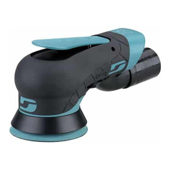
Disassembly Instructions – Mini Vacuum Dynorbital EXTREME
Models: X32V
Important: Disconnect sander from the air supply.
Notice: Use these instructions along with the tool manual. To avoid damage, use the
special repair tools designed for motor disassembly and assembly. Position 57092
Repair Collar around the housing. Fasten sander in vise with sanding pad facing up.
Do not over tighten sander in vise. Use 95263 Wrench (17 mm) to hold the balancer
shaft stationary.
To remove sanding pad, turn counterclockwise.
Advertisement

Related Manuals for Dynabrade X32V


Summary of Contents for Dynabrade X32V
- Page 1 Disassembly Instructions – Mini Vacuum Dynorbital EXTREME Models: X32V Important: Disconnect sander from the air supply. Notice: Use these instructions along with the tool manual. To avoid damage, use the special repair tools designed for motor disassembly and assembly. Position 57092 Repair Collar around the housing.
- Page 2 Motor Disassembly: Use 56061 Lock Ring Wrench to remove 59415 Lock Ring. Turn counterclockwise. ...
- Page 3 Remove motor from housing. Remove 01024 O-Ring from 59412 Cylinder Sleeve Adapter. Remove lock ring 59415 from motor assembly...
- Page 4 Fasten 96346 Bearing Separator (2") around 59411 Cylinder Sleeve. Place bearing separator and motor in 96232 Arbor Press (#2) with counterweight pointing down. Use arbor press and 5/16" or 8 mm diameter flat-end drive punch to push shaft out of 01139 Bearing. ...
- Page 5 Use 96214 Bearing Removal Tool to remove 01139 Bearing from 59405 Rear Bearing Plate.
- Page 6 Remove vanes, rotor and key.
- Page 7 Use bearing separator and arbor press to remove the front bearing plate.
- Page 8 Fasten bearing separator between 58368 Bearing and the counterweight. Place bearing separator in arbor press with counterweight pointing down. Push shaft balancer from 58368 Bearing. Motor disassembly completed.
- Page 9 Balancer Shaft and Bearing Disassembly: Fasten counterweight in vise with hex of 59407 Balancer Shaft pointing up. Use a thin slot-blade screwdriver as a pick to remove 95613 Snap Ring. (Next three views.)
- Page 11 To break adhesive bond, use two, large slot-blade screwdrivers to pry out balancer shaft and bearing. Notice: If necessary, use a HEAT GUN to warm counterweight to soften adhesive.
- Page 12 Use 54141 Bearing Puller to remove balancer shaft and 59416 Bearings (2).
- Page 13 Fasten bearing separator between 95612 Spring (Bearing Shield) and hex end of balancer shaft.
- Page 14 Place bearing separator and balancer shaft in arbor press with hex end pointing down. Use the arbor press to break the adhesive bond.
- Page 15 Use a 5/16" or 8 mm diameter flat-end drive punch as a press tool to push balancer shaft out of 59416 Bearings.
- Page 16 Balancer shaft and bearing disassembly completed. Clean and inspect parts before assembling.
- Page 17 Assembly Instructions - Dynorbital EXTREME Balancer Shaft and Bearing Assembly: Install 95612 Spring (Bearing shield) onto the 59405 balancer shaft. Face the convex side of the spring (bearing shield) toward the hex end of the balancer shaft...
- Page 18 Apply a small amount of Loctite #271 or equivalent to outside diameter of balancer shaft.
- Page 19 Use thin slot blade screwdriver to remove 3 of the 4 seals from the 59416 bearings (next three views)
- Page 21 3b. First, install the 59416 bearing with the seal. Face the sealed side of the bearing toward the 95612 Spring (Bearing Shield). Use raised inside diameter of 96244 Bearing Press Tool and arbor press to install 59416 Bearing. Press bearing to step on shaft.
- Page 22 Use small diameter of 96244 Bearing Press Tool and arbor press to install second 59416 bearing with no seals, in the same manner as the first.
- Page 23 Apply a small amount of Loctite #271 or equivalent to outside diameter of 59416 Bearing. Place 95613 Snap Ring over the hex end of the balancer shaft Install balancer shaft with bearings into shaft balancer.
- Page 24 Use a thin slot-blade screwdriver to compress and install 95613 Snap Ring into groove of shaft balancer. Balancer shaft and bearing assembly completed.
- Page 25 Motor Assembly: 1. Use small diameter of 57091 Bearing Press Tool and arbor press to install 58368 Bearing onto shaft balancer.
- Page 26 Use large diameter end of 57091 Bearing Press Tool, and arbor press to install 59408 Front Bearing Plate.
- Page 27 Install Key, and Rotor onto shaft balancer. Apply 95842 Dynabrade Air Lube 10W/NR or equivalent to vanes and install.
- Page 28 Install 95526 O-Ring into 59412 Cylinder Sleeve Adapter. Line-up tab on cylinder sleeve adapter with large single slot in 59411 Cylinder Sleeve.
- Page 29 Install 59411 Cylinder Sleeve and 591412Cylinder Sleeve Adapter so that short pins fit into front bearing plate.
- Page 30 Use LARGE DIAMETER END of 57091 Bearing Press Tool and arbor press to install 01139 Bearing into 59409 Rear Bearing Plate.
- Page 31 Notice: Carefully press bearing/plate down until it just touches the cylinder. This will produce a close fit between the bearing plates and cylinder sleeve. Apply 95842 Dynabrade Air Lube 10W/NR or equivalent to 01024 O-Ring and install into...
- Page 32 Place 57092 Repair Collar around housing. Fasten housing in vice with opening pointing up. Notice: Do not over tighten sander in vise or it will be difficult to install 59058 Lock Ring. Install 59415 Lock Ring over counterweight. Sight line-up pin with notch inside housing. Keep finger pressure against lock ring and install motor.
- Page 33 Use 56061 Lock Ring Wrench to tighten lock ring. Turn clockwise. Torque to 23 N•m/~200 lbs. in. Motor assembly completed. To install sanding pad, use 95263 Wrench (17 mm.) to hold balancer shaft stationary. Turn pad clockwise. IMPORTANT: To verify the correct RPM and tool performance, follow instructions on page 2 of tool manual.
Need help?
Do you have a question about the X32V and is the answer not in the manual?
Questions and answers