Table of Contents
Advertisement
Quick Links
Advertisement
Table of Contents

Related Manuals for Newport New Focus 3502


Summary of Contents for Newport New Focus 3502
- Page 1 Model 3502 Optical Chopper User’s Manual...
-
Page 3: Declaration Of Conformity
Year mark affixed: 2014 Type of Equipment: Electrical equipment for measurement, control, and laboratory use in industrial locations. Manufacturer: Newport Corporation 1791 Deere Avenue Irvine, CA 92606 Standards Applied: Compliance was demonstrated to the following standards to the extent applicable: BS EN61326-1: 2006 “Electrical equipment for measurement, control and laboratory use... -
Page 4: Warranty
To exercise this warranty, write or call your local New Focus office or representative, or contact Newport headquarters in Irvine, California. You will be promptly assisted and given return instructions. Send the product, freight prepaid, to the indicated service facility. We will make repairs and return the instrument, freight prepaid. -
Page 5: Confidentiality & Proprietary Rights
New Focus for release without restriction. Trademarks The New Focus logo and name are registered trademarks of Newport Corporation in Mexico, Israel, Singapore, the European Union, Taiwan, Hong Kong, China, Japan, Korea, Canada, Australia, and the United States. -
Page 6: Table Of Contents
Contents Declaration of Conformity .................... 1 Warranty ........................2 Limitation of Warranty ....................2 Confidentiality & Proprietary Rights ................3 Contents ........................4 Figures........................... 7 Safety Precautions Definitions and Symbols ..................8 1.1.1 General Warning or Caution ............... 8 1.1.2 Electrical Shock ..................8 1.1.3 European Union CE Mark ................ - Page 7 Using the Chopper How the Model 3502 Optical Chopper Works ..........16 Mounting the Unit ..................... 17 3.2.1 Chopper Head ................... 17 3.2.2 Chopper Motor ..................19 3.2.3 Mounting a Wheel..................19 3.2.4 Mounting the Wheel Cover ............... 21 Rack Mount Option ..................22 Initial Setup .......................
- Page 8 Harmonic Locking .................... 46 External Voltage Control .................. 46 General ......................46 Maintenance and Service Enclosure Cleaning ................... 47 Technical Support ..................... 47 Technical Support Contacts ................47 Service ......................48 Warranty ......................48...
-
Page 9: Figures
Figures Figure 1: Exclamation symbol................8 Figure 2: Electrical Shock symbol..............8 Figure 3: CE mark....................9 Figure 4: ON symbol..................9 Figure 5: OFF symbol..................9 Figure 6: WEEE Directive symbol..............9 Figure 7: RoHS Compliant symbol..............10 Figure 8: Warning, Certification, and Information Label. -
Page 10: Safety Precautions
Safety Precautions Definitions and Symbols The following terms and symbols are used in this manual. General Warning or Caution 1.1.1 Figure 1: Exclamation symbol. The Exclamation symbol in the figure above appears in Warning and Caution tables throughout this manual. This symbol indicates that you should read the associated documentation to determine the nature of any potential hazards and any actions that should be taken against these hazards. -
Page 11: European Union Ce Mark
European Union CE Mark 1.1.3 Figure 3: CE mark. The presence of the CE Mark on New Focus equipment means that this instrument has been designed, tested and certified compliant to all applicable European Union (CE) regulations and recommendations. 1.1.4 Figure 4: ON symbol. -
Page 12: Control Of Hazardous Substances
in a manner that protects human health and the environment. For information about where the user can drop off WEEE waste for recycling, please contact your local New Focus representative. Control of Hazardous Substances 1.1.7 Figure 7: RoHS Compliant symbol. This label indicates product compliance with the EU Directive 2002/95/EC that restricts the content of six particular hazardous substances. - Page 13 If this equipment is used in a manner not specified in this manual, the protection provided by this equipment may be impaired. Do not block ventilation openings. Use only the specified replacement parts. Follow precautions for static sensitive devices when handling this equipment.
-
Page 14: Location Of Labels And Warnings
Location of Labels and Warnings Model 3502 Optical Chopper Controller Rear Panel 1.3.1 Figure 8: Warning, Certification, and Information Label. -
Page 15: General Information
General Information System Overview The Model 3502 Optical Chopper is used to introduce a periodic interruption of a light path in an optical experiment resulting in an amplitude modulation, which is useful for many small optical signal detection schemes. The modulation frequency can be controlled from 4 Hz to 10.65 kHz. -
Page 16: Unpacking And Inspection
Unpacking and Inspection WARNING Do not attempt to operate this equipment if there is evidence of shipping damage or you suspect the unit is damaged. Damaged equipment may present additional hazards to you. Contact New Focus technical support for advice before attempting to plug in and operate damaged equipment. -
Page 17: Environmental Operation Requirement
Environmental Operation Requirement Operating Limits 2.4.1 Parameter Minimum Maximum Voltage Requirements 100V/50-60Hz 240V/50-60Hz 25 Watts Electrical Ratings 100-240 VAC 50-60 Hz 10 °C (≤ 90% humidity, non- 40 °C (≤ 90 % humidity, Operating temperature condensing) non-condensing) 0 °C (≤ 85% humidity, non- 50 °C (≤... -
Page 18: Using The Chopper
Using the Chopper How the Model 3502 Optical Chopper Works The Model 3502 Optical Chopper is designed to interrupt light paths in optical experiments at frequencies from 4 Hz to 10.65 kHz. Both single- and dual-beam experiments can be performed across a broad range of chopping frequencies. The Chopper has a crystal-controlled frequency synthesizer that serves as an internal reference frequency for locking the Chopper to a particular chopping frequency. -
Page 19: Mounting The Unit
Figure 9: Functional block diagram for Model 3502 Optical Chopper. Mounting the Unit Chopper Head 3.2.1 The Model 3502 Optical Chopper Head (Figure 10 and Figure 11) may be secured to standard optical benches using ¼”-20 or M6 bolts. The bolts pass through the mounting plate perpendicular to the plane of the optical bench. -
Page 20: Figure 10: Model 3502 Optical Chopper Head With Wheel Cover Installed
Figure 10: Model 3502 Optical Chopper Head with wheel cover installed. -
Page 21: Chopper Motor
Figure 11: Dimensions of Model 3502 Optical Chopper Head. Dimensions in inches (mm). Chopper Motor 3.2.2 The operating life of the Chopper motor is limited. Long-term use of the motor at high speed will result in faster wear and a shorter lifetime. Contact New Focus for details about replacing the motor, if this becomes necessary. -
Page 22: Figure 12: Chopper Wheels
Figure 12: Chopper wheels. Top row: 2-slot and 60/2-slot wheels. Middle row:7/5-slot and 42/30-slot wheels. Bottom row: 60-slot and 100-slot wheels. All wheels are 4.50” (114.3 mm) O.D. -
Page 23: Mounting The Wheel Cover
WARNING The moving wheel may inflict injury. The operator should ensure the safety of personnel who may be exposed to this hazard. Mounting the Wheel Cover 3.2.4 WARNING The wheel cover is provided for safety and its installation is encouraged. The Chopper wheel can cause injury if it is touched while rotating. -
Page 24: Rack Mount Option
Rack Mount Option The Model 3510 Rack Mount Kit is a Chopper accessory that allows one or two Chopper Controllers to be mounted in a standard rack. The kit consists of two short ears, one long ear, one rack plate, and six 6-32 flathead screws. The figure below illustrates how to use the rack mount kit to mount a single Chopper Controller or two Chopper Controllers side-by-side. -
Page 25: Power
Power 3.4.1 Make sure that that power switch is in the position. Connect the male end of the provided AC power cable to the mains supply. Connect the female end to the three-pronged input receptacle on the back of the Chopper Controller. WARNING To avoid electric shock, connect the instrument to building earth- ground, 3-prong receptacles by using the supplied power cord only. -
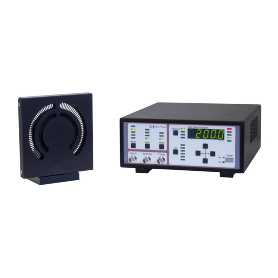
Page 26: Front Panel Operation
Front Panel Operation 3.5.1 The Model 3502 Optical Chopper can be operated manually by keying in control functions from the Chopper Controller front panel shown below. Figure 14: Model 3502 Optical Chopper Controller front panel. Wheel Button The User may select from different wheels to accommodate the chopping frequency of interest. - Page 27 For setups requiring very low chopping frequencies and high stability the 60/2- slot wheel may be used. There is no wheel setting for this particular wheel on the front panel—the 60-slot wheel setting must be selected. The actual chopping frequency will differ from that displayed on the front panel by a factor of 2/60 = 1/30.
- Page 28 Mode Setting locked to OUT 1 OUT 2 outer (H/S) F (H/S) F [H/(7 S)] F Sync sync sync – F sync outer inner outer inner Normal sync inner sync Table 1: Chopping frequency and outputs vs. mode setting. For all wheels with a dual slot pattern (except for the 60/2-slot wheel), F outer 7/5·F .
- Page 29 When the setting is selected for the source, the synthesizer frequency Sync will be restricted to the working range of the particular chopping wheel. In mode this range will be modified by the user-specified values of and S according to: = (S/H)·F , highest, outer...
- Page 30 Set: RECALL The user may recall an instrument setup in one of two ways. Firstly, on power up, the instrument will recall the last control settings used. Secondly, a previously stored setup can be recalled by pressing the button until the LED is lit.
- Page 31 OUT 1 OUT 2 outer Phase Phase Sync Mode Phase is Source Output Freq. Output Freq. Output Freq. locked locked locked to 5·(Int. F Int. F (5/7)·(Int. F Int. F Int. F Int. F sync sync sync sync sync sync Ext+, 5·(Ext.
-
Page 32: Back Panel Operation
Back Panel Operation The back panel of 3502 Optical Chopper Controller provides the functions operation described below. Figure 15: Model 3502 Optical Chopper Controller back panel. CAUTION Do not block the rear panel of the Controller. Ensure a minimum clearance of 30” for adequate ventilation of the device. Blocking the normal convective airflow around the unit, or thermally insulating the unit, can result in severe injury, damage to the product, and/or fire. - Page 33 MOTOR socket The input marked MOTOR on the rear panel is used to connect the 3502 Optical Chopper Head to the Chopper Controller with the shielded Ethernet cable provided. USB 2.0 The USB-B input port is used in connecting the Chopper Controller to a host computer system.
-
Page 34: Computer Interfacing
’, containing the New Focus Chopper Application and supporting files; ‘ Docs ’, containing documentation of the GUI Application, the programming examples and the Newport USB library API documentation; and ‘ ’, containing C# and LabVIEW examples to get Samples you started with remote operation of the Model 3502 Optical Chopper. -
Page 35: A Quick Start: How To Use The 'New Focus Chopper Application
Figure 16: Model 3502 Optical Chopper Application window. A Quick Start: How to Use the ‘New Focus Chopper 4.2.1 Application’ 1. Turn the Model 3502 Optical Chopper Controller on using the power button on the front panel of the Controller. 2. -
Page 36: Usb Communication
USB Communication To control the Model 3502 Optical Chopper remotely without using the GUI application, commands can be issued directly over USB using the Newport USB library. The API is described in detail in the document ‘ Chopper USB Libraries ’. - Page 37 Sets the harmonic multiplier (1 - 15). HAR[ ]? Identification query. Returns “NEW FOCUS 3502 CHOPPER IDN? <Firmware version> <Firmware date>, SN<Serial Number>”. Duplicates the action of pressing a front panel key: 0 = Right arrow, 1 = Down arrow, 2 = Up arrow, 3 = Left arrow, KEY* 4 = Set, 5 = Measure, 6 = Mode, 7 = Sync, 8 = Wheel.
-
Page 38: Command Description
Command Description FR*? Description Frequency query. Syntax FR*? Remarks The FR* command is used to query the following frequencies associated with the key on the Chopper front panel: Measure sync , and . Data is returned in Hz. OUT 1 OUT 2 outer Query F... - Page 39 IDN? Description Identification query. Syntax IDN? Remarks Returns the following string identifying the Chopper: "NEW FOCUS 3502 CHOPPER <Firmware version> <Firmware date>, SN<Serial Number>". Example Query. IDN? Response. The firmware version is 1.16, NEW FOCUS the firmware date is 5/05/14, and the 3502 serial number of the unit is P0004.
- Page 40 MEM? Description Store and recall instrumental set-ups. Syntax MEM? Remarks The MEM command, along with the STO and RCL commands, is used to store and recall one of the 9 instrumental set-ups. After selecting which instrument set-up number to use (1 through 9) using the STO command, MEM0 will store the current instrument set-up.
- Page 41 OSC[ ]? Description Set and query the synthesizer frequency. Syntax OSC[ ]? Remarks OSC command sets and queries the internal synthesizer. In mode setting the synthesizer frequency will set the chopping Sync frequency. In INT Sync mode the data supplied by the OSC command is limited by the Chopper wheel minimum and maximum chopping frequencies.
- Page 42 RCL[ ]? Description Selects instrument set-up for recall. Syntax RCL[ ]? Remarks RCL command will select a formerly stored instrument set-up. The RCL? query will return the recall set-up number. The data may range between 0 and 9. Recall of set-up “0” will restore the Model 3502 Optical Chopper to factory default settings.
- Page 43 STO[ ]? Description Selects instrument set-up for storage. Syntax STO[ ]? Remarks command selects the instrument set-up number in which to store the current Chopper set-up. The query will return STO? the selected instrument set up number. The data may range from 1 to 9.
- Page 44 SYN[ ]? Description Set and query the source used for synchronization. Syntax SYN[ ]? Remarks The SYN command sets and queries the frequency source used for synchronization. SYN0 Ext+ SYN1 Ext- SYN2 SYN3 Query SYN? Example SYN3 Command. Set sync source to INT. SYN? Query.
-
Page 45: Troubleshooting
Troubleshooting CAUTION There are no user serviceable parts inside the Model 3502 Optical Chopper Controller or Motor Head. Work performed by persons not authorized by New Focus will void the warranty. Normal Startup Operation When the Chopper Controller is properly connected to the power mains and a Chopper Head, and is turned on, the front panel LEDs will blink and the display will show before recalling the last Chopper Controller set up. - Page 46 Synchronization to an external signal is unreliable: Verify that the pulse width of the external trigger pulse is at least 1 μs long. Use an oscilloscope with a high impedance input to monitor the external signal while it is connected to the Chopper Controller. The input signal should have valid TTL voltage levels.
-
Page 47: Specifications
Specifications Chopping Frequency Please note that specifications are subject to change without notice. Min. Freq. Max. Freq. Jitter ( s p-p, typical) Wheel @ Min. @ Max. outer outer Freq. Freq. 200 Hz 10.65 KHz 120 Hz 6.40 KHz 42/30 84 Hz 4.48 KHz 14 Hz... -
Page 48: Reference Output
Reference Output Sync Out TTL level square wave, may be used as free-running oscillator when using EXT+ EXT- Sync setting. TTL-level square wave at the chopping frequency. outer TTL level pulse: OUT 1 5·F mode NORMAL outer in +/- mode outer inner (H/S)·F... -
Page 49: Maintenance And Service
Maintenance and Service Enclosure Cleaning Before cleaning the enclosure of the Model 3502 Optical Chopper Controller, the power cord must be disconnected from the wall socket and from the unit. The source enclosure should only be cleaned with a mild soapy water solution applied to a damp lint-free cloth. -
Page 50: Service
Warranty New Focus, a Newport Corporation company, guarantees its products to be free of defects for one year from the date of shipment. This is in lieu of all other guarantees, expressed or implied, and does not cover incidental or consequential... - Page 51 Note that the life of the motor is limited. Long-term high-speed use of the motor will result in faster wear and a shorter lifetime. Because of this limited lifetime, the Chopper Head has a 90 day warranty, while all other parts have a one year warranty.
Need help?
Do you have a question about the New Focus 3502 and is the answer not in the manual?
Questions and answers