Table of Contents
Advertisement
TALKBACK INTERCOM SYSTEM
The V-2928 Option Board is an add-on feature for the V-2924A Expandable Zone Talkback Intercom
System. The addition of this board provides the following supplemental features:
Time sync output
Custom page groups
Enhanced Caller ID
Flexible Architectural numbering plan
Interface to the PC Programming Tool
Store user data to EEROM
Dimensions/Weight
5.3" L x 3.00" W x 1.10" D
(13.46cm L x 7.62cm W x 2.79cm D)
0.9 lbs (0.41 kg)
The V-2924A Programming Tool is a windows based
software tool designed to interface with the V-2928
Option Board. The Option Board and the Programming Tool must both be installed to access the
additional features provided by the Option Board. All features must be set with the Programming Tool
when the Option Board and Programming Tool are installed.
CONTENTS
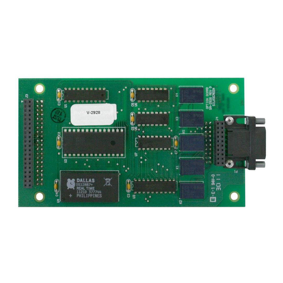
Figure 1 - Option Board Location on the Control Board
Modem Connect, Manual Connect
Print, Window, Help, Exit
V-2928 OPTION BOARD
1
Real time clock for SMDR printer
Auto detect for Com Port or Modem
Evacuation tone to specified groups
Time tones to any of the Pre-Determined
Groups selected
Read software/firmware revision numbers
11,12
13,14
15,16
16,17
18-21
21-23
Issue 5
2
2
3
4
4,5
6,7
7,8
8
9
10
14
15
15
15
17
17
17
23
24
947150
Advertisement
Table of Contents

Related Manuals for Valcom V-2928


Summary of Contents for Valcom V-2928
-
Page 1: Table Of Contents
Issue 5 TALKBACK INTERCOM SYSTEM V-2928 OPTION BOARD The V-2928 Option Board is an add-on feature for the V-2924A Expandable Zone Talkback Intercom System. The addition of this board provides the following supplemental features: Time sync output Real time clock for SMDR printer ... -
Page 2: Installation Of The Option Board
Plug PC Communication Cable (included) into P1, PC Programming Port (located on the Option Board - See Figure 1). The V-2928 Option Board requires the use of the PC Programming Tool to access the various features it provides. INSTALLATION OF THE PROGRAMMING TOOL... - Page 3 FIGURE 1 - OPTION BOARD LOCATION ON THE V-2928 CONTROL BOARD Top View Side View RS232 Serial Port for SMDR (DB9 Connector) P10 P1 Option Board J3 and J4 are located on the Location PC Programming under side of the Option Board.
-
Page 4: Using The Programming Tool
USING THE PROGRAMMING TOOL On the taskbar, click the Start button, point to Programs and select VALCOM V-2924sc Programming Tool. The V-2924 Programming Tool splash screen appears momentarily and then the Programming screen comes into view. System Configuration To begin the programming process, click on File. - Page 5 When OK is selected from the System Configuration screen, the Programming Window appears - see below. The Programming Window allows each option to be accessed by selecting the option and pressing Open or by double clicking on the selected option. All functions can be listed at once by pressing Open All. (All of the options accessed through the Programming Window can also be accessed from the pulldown menus).
-
Page 6: Architectural Number And Clid Programming
Architectural Number and CLID (Caller ID) Programming The first function to configure is the Architectural Number and CLID Programming. The Architectural Number is a 1 to 4 digit number that is dialed by the phone to connect to a specific speaker. Flexible architectural numbering is often selected to allow speakers and room numbers to match. -
Page 7: Audio Connection
Audio Connections This screen allows selection of groups to receive Background Music, Time Tones and Emergency Tones. This sample system consists of a "Main Board + Expansion 1" so eight groups are available to receive audio connections. (Each group contains six stations). Group 1 Stations 1, 2, 3, 4, 5, 6 Main Board... -
Page 8: Class Of Service
The Audio Connections screen disappears, with the Programming Window still being active to allow selection of other options. Class of Service. Class of Service defines how a call originated by a button press will be queued for answer by the attendant. ... -
Page 9: Clock
Clock Note: Clock programming option is available if Clock Board has been checked on System Configuration screen. Clock correction is only available with the V-CLK2924 Clock Correction Kit. When Clock is selected, the following screen is displayed. Click on the tab for Clock A. Then click on the down arrow next to Clock Type, and select the clock type code (codes are defined in the V-2927 manual) for the Clock Circuit 1 connections on the V-CIO. -
Page 10: Custom Page Groups
Custom Page Groups When Custom Page Groups is selected, the following screen is displayed. There are 4 Custom Page Groups available. Select the Page Groups to receive custom paging by clicking on the desired box. Each Custom Page Group can contain all groups or a combination of groups. (Example: Custom Page Group 50 could contain page groups 1, 2 and 3, and Custom Page Group 52 could contain page groups 1, 2, 7 and 8). -
Page 11: Master Clock Schedule
Master Clock Schedule The Master Clock Schedule has 6 separate schedules with up to 256 total events. The user defines how these events are to be distributed between schedules. Dial codes may be used to force a schedule or to turn a schedule off. #94X forces schedule on with the X being the number of the schedule (i.e. - Page 12 New Event Screen menu will be shown. Select Start Time. Select which Relay Type you want to follow the Schedule and Select the Relay Duration of the contact closure. Select which Page Group(s) tone should go to. Select Save. NOTE: The contact closure pairs 13, 14, 15, 16 on the system punchdown block, should be wired to the tone select input of an external tone generator (V-9927A).
-
Page 13: System
System Note: If Clock Board was checked in system configuration, you will need to scroll down to find System in the Programming Window. Next select System from the Programming Window. A check in the box means ON (selected); an empty box means OFF (not selected). -
Page 14: Save Programmed Data To File
Dip switch equivalent of programmed options. Save Programmed Data to a File When the programming selections are complete, click on the File menu option to access the pull-down menu and select Save. Define file name and location and press Save. -
Page 15: Communicating With The V-2924A
V-2924A. See page 18 for Setup of the Remote Modem. Serial Port The serial port on the V-2928 Option Board is set for 9600 bits/second, 8 data bits, no parity and 1 stop bit (9600-8-N-1). The serial port properties of the connected PC or modem must be set to match these parameters. -
Page 16: Send Data To V-2924A/Receive Data From V-2924A
Once the desired phone number is displayed in the Number to Dial field, click on the Dial button. Messages should be displayed stating, "Initializing", "Dialing" and "Modem Connection Successful". Click on OK. If modem fails to connect, verify modem was set up properly during system installation. Refer to section titled, "Setup of the V-2924A Modem,"... -
Page 17: Set System Date And Time
Receive Data from V-2924A From the main menu, select Receive Data from V-2924. This will take place automatically. If you are not allowed to select Receive Data from V-2924, close the currently open file and try again. Messages will be displayed stating Receiving Data, Receive Data Completed Successfully. -
Page 18: Setup Of The V-2924A Modem
SETUP OF THE V-2924A MODEM 1. To transfer data from a PC through a modem to the V-2924A System, the Remote Modem must be setup. THIS IS A "ONE-TIME" PROCEDURE THAT SHOULD BE PERFORMED WHEN THE MODEM IS INSTALLED. Select Communications Setup from the File Menu as shown in the following screen display: 2. - Page 19 The following screen is displayed after selecting No from the question of using a US Robotics modem or after selecting Yes, setting the dip switches and pressing OK. 4. Complete the instructions on the screen and click OK. The next screen to be displayed requests selection of a COM Port.
- Page 20 6. The default modem commands for the US Robotics Sportster appear below. Click on Enter to send these commands to the modem. 7. Save the settings to the modem's memory by selecting "Yes" as shown in the figure below.
-
Page 21: Menu Options
8. If "Yes" was selected in step 2, now with the modem power OFF, set the dip switches to the settings shown below and then click on OK. For a description of "DIP" switch functions, refer to the table below. Dip Switch Description Number... - Page 22 To access this option, select File and then Print. A screen (shown below) appears to allow selection of all programmed options or individual options for printing. This screen shows all items selected for printing. WINDOW The pull-down menu titled Window, allows several screens to be closed at once. Instead of going through several open screens, closing them individually, select Window, Close All or select the screens individually from the pull-down window.
-
Page 24: Additional Hardware Connections
VALCOM LIMITED WARRANTY Valcom, Inc. warrants its products only to the original purchaser, for its own use, to be free from defects in materials and workmanship under conditions of normal use and service for a period of one year from the date of shipment. This Limited Warranty obligation shall be limited to the replacement, repair or refund of any such defective device within the warranty period, provided that: 1. -
Page 25: Power Supply
CONTACT CLOSURE CONNECTIONS * TO P7 FROM THE OPTIONS CARD V-9927A UNMUTE BURST Block P7 - System Inputs MUTE CONT WH/BL BL/WH WH/O O/WH WH/GR TONE BANK SELECT GR/W W/BR BR/W R/BL BL/R TONE LEVEL POWER SUPPLY POWER -24VDC R/BR BR/R BK/BL BL/BK...
Need help?
Do you have a question about the V-2928 and is the answer not in the manual?
Questions and answers