Table of Contents
Advertisement
Quick Links
700 (60 Hz) / 572 (50 Hz) Horsepower
912 (60 Hz) / 752 (50 Hz) Horsepower
THIS MANUAL CONTAINS RIGGING, ASSEMBLY, START-UP, AND
MAINTENANCE INSTRUCTIONS. READ THOROUGHLY BEFORE
BEGINNING INSTALLATION. FAILURE TO FOLLOW THESE
INSTRUCTIONS MAY RESULT IN PERSONAL INJURY OR DEATH,
DAMAGE TO THE UNIT, OR IMPROPER OPERATION.
Please check www.johnsoncontrols.com for the latest version of this publication.
Form 100-210 IOM (JUL 2009)
INSTALLATION - OPERATION - MAINTENANCE
File:
SERVICE MANUAL - Section 100
Replaces:
S100-210 IOM (FEB 09)
Dist:
3, 3a, 3b, 3c
Advertisement
Table of Contents

Subscribe to Our Youtube Channel
Related Manuals for Frick Vyper 700


Summary of Contents for Frick Vyper 700
- Page 1 Form 100-210 IOM (JUL 2009) INSTALLATION - OPERATION - MAINTENANCE File: SERVICE MANUAL - Section 100 Replaces: S100-210 IOM (FEB 09) Dist: 3, 3a, 3b, 3c 700 (60 Hz) / 572 (50 Hz) Horsepower 912 (60 Hz) / 752 (50 Hz) Horsepower THIS MANUAL CONTAINS RIGGING, ASSEMBLY, START-UP, AND MAINTENANCE INSTRUCTIONS.
-
Page 2: Table Of Contents
TRANSFORMERS ..............24 ™ OVERVIEW ................59 POWER FACTOR CAPACITORS ..........24 SOFT-START SEQUENCE ............25 FRICK VYPER FAULT CODE LIST .......... 59 ™ FAULT CODEFAULT CODE DESCRIPTIONS ......60 INTERFERENCE WITH ELECTRONICEQUIPMENT ....25 INTERFACING ELECTRICAL EQUIPMENT ......25 INDEx ..................70... - Page 3 Figure 5B - Harmonic Filter Elementary Wiring Diagram ... 15 Figure 43 - Vyper™ Screen ............43 Figure 6 - Vyper Package Mounted on Frick RWF II 134 ..17 Figure 44 - Harmonic Filter Screen ..........44 ™ ™...
-
Page 4: Preface
Unpack all items and check against shipping an adequately controlled refrigeration system. Consult an lists for any possible shortage. Examine all items for damage author ized Frick repre sentative for expert guidance in this from unit transit. determination. -
Page 5: Unit Identification
Oil Pump - Large HP (L) right side of the cabinet. The data plate contains the Frick - Small HP (S) Part Number, the unique Serial Number, and the basic Model Number for the unit. In addition, the data label also IEEE 519 Filter - Installed (F) has electrical information pertinent to the individual unit. -
Page 6: Model Descriptions
VYPER VARIABLE SPEED DRIVE ™ Page 6 INSTALLATION - OPERATION - MAINTENANCE MODEL DESCRIPTIONS These tables provide the model number, Frick part number and basic description of each Vyper Drive covered in this manual. ™ Model No. Frick P/N Description... -
Page 7: Vyper Pre-Installation Site Check List
The following items MUST be checked and completed by the installer prior to the arrival of the Frick Field Service Supervisor. Details on the checklist can be found in the I.O.M. Certain items on this checklist will be re-verified by the Frick Field Service Supervisor prior to the actual start-up. -
Page 8: Pre-Startup Inspection
™ Operation Site Checklist. Any changes to factory setpoints, it is operating. Once it has moved to one end of the needs to be approved by Frick . Failure to obtain approval stroke, change the Direction back to Forward. This ®... -
Page 9: Vyper System Overview
COMPONENT DESCRIPTION ™ Logic board. The inverter section is actually composed of three identical inverter output phase assemblies. These as- The Frick Vyper ™ Variable Speed Drive is a liquid-cooled, semblies are in turn composed of a series of Insulated Gate transistorized, PWM inverter in a highly integrated package. -
Page 10: Figure 2A - Vyper ™ Elementary Wiring Diagram
VARIABLE SPEED DRIVE ™ Page 10 INSTALLATION - OPERATION - MAINTENANCE NOTE: Drawings for specific units can be found in the door of the Vyper Drive or check with Frick Engineering department. Figure 2A - Vyper Elementary Wiring Diagram ™... -
Page 11: Figure 2B - Vyper ™ Elementary Wiring Diagram
100-210 IOM (JUL 09) ™ INSTALLATION - OPERATION - MAINTENANCE Page 11 NOTE: Drawings for specific units can be found in the door of the Vyper Drive or check with Frick Engineering department. Figure 2B - Vyper Elementary Wiring Diagram ™... -
Page 12: Harmonic Filter
100-210 IOM (JUL 09) VYPER VARIABLE SPEED DRIVE ™ Page 12 INSTALLATION - OPERATION - MAINTENANCE HARMONIC FILTER The Three-Phase Inductor provides some impedance for the filter to “work against”. The inductor effectively limits the The VSD system may include an harmonic filter designed to rate of change of current at the input to the filter to a reason- meet the IEEE Std 519 -1992, “IEEE Recommended Practices able level. -
Page 13: Figure 3 - Vsd Input Current Without Harmonic Filter
VYPER VARIABLE SPEED DRIVE 100-210 IOM (JUL 09) ™ INSTALLATION - OPERATION - MAINTENANCE Page 13 Figure 3 - VSD Input Current Without Harmonic Filter Figure 4 - VSD Input Current With Harmonic Filter... -
Page 14: Figure 5A - Harmonic Filter Elementary Wiring Diagram
VARIABLE SPEED DRIVE ™ Page 14 INSTALLATION - OPERATION - MAINTENANCE NOTE: Drawings for specific units can be found in the door of the Vyper Drive or Figure 5A - Harmonic Filter Elementary Wiring Diagram check with Frick Engineering department. -
Page 15: Figure 5B - Harmonic Filter Elementary Wiring Diagram
100-210 IOM (JUL 09) ™ INSTALLATION - OPERATION - MAINTENANCE Page 15 NOTE: Drawings for specific units can be found in the door of the Vyper Drive or Figure 5B - Harmonic Filter Elementary Wiring Diagram check with Frick Engineering department. -
Page 16: General Operation Description
414 to 508 VAC, 3 phase, 60 Hz, or 342 to 423 VAC, 3 phase, If one or more of these conditions exist, Frick recommends 50 Hz. Refer to Table 2. -
Page 17: Installation
Package mounting is available for all horsepower sible by portable means. ratings of the Vyper . Both water or glycol cooling connec- ™ Figure 6 - Vyper Package Mounted on Frick RWF II. Diagram is for orientation purposes only and is not to scale. ™... -
Page 18: Figure 7 - Vyper ™ Cabinet And Stand
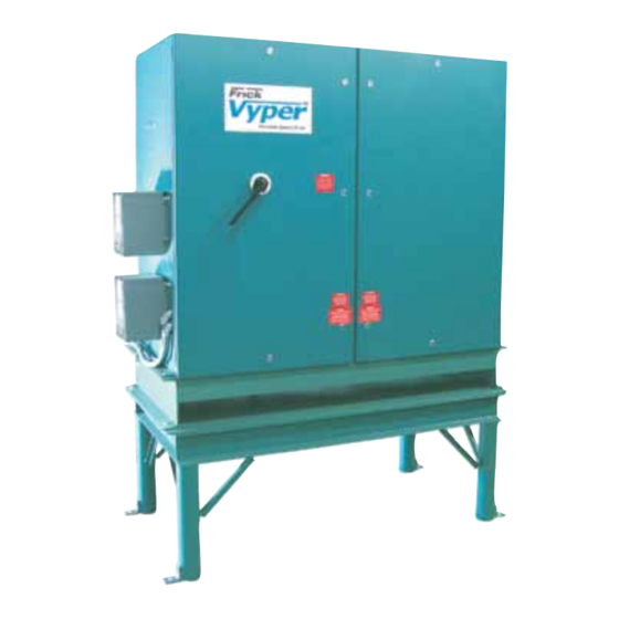
100-210 IOM (JUL 09) VYPER VARIABLE SPEED DRIVE ™ Page 18 INSTALLATION ™ Figure 7 - Vyper Cabinet and Stand... -
Page 19: Remote Mounted Units
The primary requirement for mounting the Vyper is that the ™ foundation must be able to support the weight of the cabinet The Frick Vyper ™ is internally cooled with a factory cali- and stand. In addition, the remote stand and Vyper ™... -
Page 20: Coolant Temperature Limits
Glycol 35°F (2°C) 105°F (41°C) • Frick recommends a water pH level between 6.0 and 7.4 Table 8 – Entering Coolant Temperature Limits. for proper heat exchanger life. GENERAL COOLING SYSTEM • When adding a booster pump to supply condenser water... -
Page 21: Heat Exchanger Pressure Drop
VYPER VARIABLE SPEED DRIVE 100-210 IOM (JUL 09) ™ INSTALLATION Page 21 Figure 9 - Minimum Flow Rates - GLYCOL HEAT ExCHANGER PRESSURE DROP 912, 752, 700, 572 Models In order to adequately size piping and booster pump require- designers with pressure drop reference for different mixtures ments, the pressure drop of the coolant across the heat of propylene glycol and water. -
Page 22: Figure 11 - Vyper ™ P&I Diagram - Noneconomized
100-210 IOM (JUL 09) VYPER VARIABLE SPEED DRIVE ™ Page 22 INSTALLATION ™ Figure 11 - Liquid Cooled Vyper P&I Diagram - Noneconomized Figure 12 - Liquid Cooled Vyper ™ P&I Diagram - Economized... -
Page 23: Power Wiring
Copper wire is required for all power wiring connected to the system. Aluminum wiring is NOT acceptable for use The general specification of the wire is also dictated by the environment in which the wire is used. The Frick Vyper is a ™... -
Page 24: Control Wiring
100-210 IOM (JUL 09) VYPER VARIABLE SPEED DRIVE ™ Page 24 INSTALLATION CONTROL WIRING Johnson Controls offers a line of recommended Vyper VSD Transformers. These transformers have the following NOTE: Use 18AWG (0.750 mm ) twisted pair, 100% shield features: with drain. -
Page 25: Soft-Start Sequence
At start-up, both the motor and slide valve begin to load to a picking up low-voltage DC signals and possibly cause injury preset value. The Frick slide valve will load to the “Minimum or damage to the electronic controls: Slide Valve Position” setpoint and the Vyper will accelerate ™... -
Page 26: Vyper ™ Preinstallation Site Checklist
100-210 IOM (JUL 09) VYPER VARIABLE SPEED DRIVE ™ Page 26 INSTALLATION VYPER PREINSTALLATION SITE CHECKLIST ™ Before attempting to install a Vyper Drive system, please perform a site inspection to assure that the following requirements ™ are met. (Where Applicable) �����������������������... -
Page 27: External Power And Control Wiring
VYPER VARIABLE SPEED DRIVE 100-210 IOM (JUL 09) ™ INSTALLATION Page 27 ExTERNAL POWER AND CONTROL WIRING Shock Hazard! Before beginning service, use proper lock-out/tag-out procedures to disconnect all power supplies related to this equipment. Verify all power is removed from the supply leads. Death or severe personal injury will occur if proper care is not taken. -
Page 28: Output Power Connection (Remote Mount)
100-210 IOM (JUL 09) VYPER VARIABLE SPEED DRIVE ™ Page 28 INSTALLATION OUTPUT POWER CONNECTION (REMOTE MOUNT) The output power attachment lugs are labeled “T1”, “T2”, and “T3” are located on the inside right rear wall of the Vyper ™ Prepare the output power leads by stripping 0.5 to 1.0 inch cabinet (See Figure 19). -
Page 29: Vyper Wiring And Wiring Diagrams
VYPER WIRING AND WIRING DIAGRAMS ™ Figures 20 through 25 provide the wiring terminations for the Frick Vyper Drive. These drawings illustrate the necessary ™ connections required to install the unit. Always refer to the wiring diagrams included inside the... -
Page 30: Figure 22 - Analog Board Wiring
100-210 IOM (JUL 09) VYPER VARIABLE SPEED DRIVE ™ Page 30 INSTALLATION THIS WIRING MAY GO TO ANA 1 OR 2 ANALOG BOARD NOT NECESSARILY MOUNTED IN THIS POSITION OV OR COM ñ CABLE #29 TE-6 ICTD VYPER COOLING TEMP SENSOR ANALOG BELDEN #8762 OR EQUAL BOARD... -
Page 31: Motor Thermal Protection Options
The National Electrical Code (NEC) requires thermal protection for motors operating with variable-speed drive systems. Frick employs two types of thermal protection for motors. One method uses thermistors, and one method uses RTDs. Figures 23 and 24 show the wiring schematics for both op- tions. -
Page 32: Vyper Preoperation Site Checklist
100-210 IOM (JUL 09) VYPER VARIABLE SPEED DRIVE ™ Page 32 INSTALLATION VYPER PREOPERATION SITE CHECKLIST ™ Prior to Quantum LX setup and starting operation of the Vyper Drive system, review the following checklist to ensure all instal- ™ ™ lation requirements are met. -
Page 33: Blower Motor Rotation
VYPER VARIABLE SPEED DRIVE 100-210 IOM (JUL 09) ™ INSTALLATION Page 33 BLOWER MOTOR ROTATION The Blower Motor rotation is marked on the blower assembly and is to be such that the blower draws into the assemly through the screen and pushes down and through the motor. COOLANT CONTAMINATION AND Should it be necessary to remove the coolant fro any rea- son, such as equipment repair, discard the old coolant and... -
Page 34: Adding And Replacing Coolant
Be sure that the hose is connected system once per year. The Frick part number for a one tightly to the drain fitting so no fluid is spilled. -
Page 35: Figure 30 - Refilling The Cooling System
VYPER VARIABLE SPEED DRIVE 100-210 IOM (JUL 09) ™ INSTALLATION Page 35 Step 4: (Figure 30) Close the drain valve and refill the cooling Step 7: (Figure 33) Replace and tighten the plug on the top system with the new coolant. of the manifold using an adjustable wrench. -
Page 36: Operation
The motor speed is allowed to This section is provided to briefly familiarize the operator drop as low as the capacity control “Drive Speed” setpoint. with the user interface of the Frick Quantum ™ LX control When the motor speed reaches this point, depending on the panel. -
Page 37: Quantum Lx Panel Setup
LX software provides the necessary controls Specific options and setpoints must be configured at the ™ to operate Vyper ™ Drive and optional Harmonic Filter on Frick Quantum ™ LX control panel. These settings will provide the screw compressors. This is accomplished through the recep-... -
Page 38: Setting User Level
100-210 IOM (JUL 09) VYPER VARIABLE SPEED DRIVE ™ Page 38 OPERATION SETTING USER LEVEL Step 1: (See Figure 36) Set the User Level. Advance to the pull-down menu. Use the keypad to enter Service Level 2 Session Screen by pressing the panel [Menu] key and then under the “User Level”... -
Page 39: Configuring Compressor Operation
VYPER VARIABLE SPEED DRIVE 100-210 IOM (JUL 09) ™ OPERATION Page 39 CONFIGURING COMPRESSOR OPERATION Step 1: (See Figure 38) Verify the Vyper Drive is set to be ™ controlled by the Quantum LX panel. Press the [Menu] ™ ` key and select “Configuration”... -
Page 40: Programming Vyper™ / Quantum™Lx Communications
100-210 IOM (JUL 09) VYPER VARIABLE SPEED DRIVE ™ Page 40 OPERATION PROGRAMMING VYPER™ / QUANTUM™Lx COMMUNICATIONS Step 1: (See Figure 39) The communication rate between the Vyper and the Quantum LX requires programming. ™ ™ Advance to the Communications Screen by pressing the [MENU] key and then selecting “Setpoints”... -
Page 41: Programming Pid Setup
VYPER VARIABLE SPEED DRIVE 100-210 IOM (JUL 09) ™ OPERATION Page 41 PROGRAMMING PID SETUP Step 1: (See Figure 40) The PID Setup Screen requires programming so that the Quantum LX panel will control ™ the cooling system for the Vyper Drive. -
Page 42: The Vyper And Harmonic Filter Screens
100-210 IOM (JUL 09) VYPER VARIABLE SPEED DRIVE ™ Page 42 OPERATION THE VYPER AND HARMONIC FILTER SCREENS ™ Step 1: (See Figure 41) Advance to the Vyper Screen by ™ pressing the [MENU] key and then selecting “Setpoints” and “Operating Values”... -
Page 43: Vyper Screen Setpoints
VYPER VARIABLE SPEED DRIVE 100-210 IOM (JUL 09) ™ OPERATION Page 43 Figure 43 - Vyper™ Screen VYPER SCREEN SETPOINTS • Actual Speed (RPM) • Speed Command (RPM) The Vyper ™ Screen (See Figure 43) contains setpoints and information pertinent to the operation of the Vyper such as ™... -
Page 44: Harmonic Filter Screen
100-210 IOM (JUL 09) VYPER VARIABLE SPEED DRIVE ™ Page 44 OPERATION Figure 44 - Harmonic Filter Screen HARMONIC FILTER SCREEN The status of the following parameters are indicated using a binary number next to the field description (See Table 16). The Harmonic Filter screen (See Figure 44) shows important •... -
Page 45: Programming The Motor Screen
VYPER VARIABLE SPEED DRIVE 100-210 IOM (JUL 09) ™ OPERATION Page 45 PROGRAMMING THE MOTOR SCREEN High Motor Amps (See Figures 46 and 47) The various portions of the Motor Screen require program- The setpoints in “High Motor Amps” section of the Motor ming in order to control the compressor motor and Vyper ™... -
Page 46: High Motor Amp Limit Examples
100-210 IOM (JUL 09) VYPER VARIABLE SPEED DRIVE ™ Page 46 OPERATION Step 3: (See Table 17 or 18) Use High Motor Amps Calcu- High Motor Amp Limit Examples lations Table A or B based on the following: Example 1 (See Figures 48 and 49) What are the High Motor •... -
Page 47: Vfd Setpoints
Nameplate FLA by 1.15 or an Applied motor FLA. This is be limited. The Maximum Percentage parameter range can calculated as shown: be set from 0 to 100%. However, Frick recommends that the Maximum percentage is always set to a higher value than the 1245 Amps Minimum Percentage parameter setting. -
Page 48: Capacity Control Setpoints
Minimum Slide Valve Position - This setting establishes the acceleration rate step. minimum Slide Valve position possible while the Frick screw Rate of Decrease Delay Time* - The Rate of Decrease compressor is running. At Minimum Drive Speed, this is the Delay Time setpoint is used in conjunction with the Rate of point at which no further mechanical unloading is allowed. -
Page 49: Suggested Vfd And Capacity Control Settings
VYPER VARIABLE SPEED DRIVE 100-210 IOM (JUL 09) ™ OPERATION Page 49 Suggested VFD and Capacity Control Settings Figure 58 provides the VFD and Capacity Control setpoints typical for operation. There are individual control strategies required for various industries. The Vyper VFD and Capacity control settings ™... -
Page 50: Figure 59 - 5:1 Turndown Suggested Control Strategy
NOTE: Slide Valve Range limited to protect compressor Slide Valve Position setting in order to keep the Slide Valve loaded at a much higher level. Frick recommends that the Figure 60 - Example 2 VFD and Capacity Control Setpoints slide valve position for 5:1 applications be set as high as 97%. -
Page 51: Compressor Safeties Screen
VYPER VARIABLE SPEED DRIVE 100-210 IOM (JUL 09) ™ OPERATION Page 51 Compressor Safeties Screen To prevent the Slide Valve from unloading beyond a high setpoint level (97%) and permit rapid compressor response under load, make the following setting adjustments on the Compressor Safeties Screen: Step 1: Press the [MENU] key and then selecting “Setpoints”... -
Page 52: Figure 62 - 2:1 Turndown Suggested Control Strategy
100-210 IOM (JUL 09) VYPER VARIABLE SPEED DRIVE ™ Page 52 OPERATION Example 2 - Suggested Control Strategy for Standard 2 to 1 (2:1) Turndown Figure 62 - 2:1 Turndown Suggested Control Strategy NOTE: The Variable Speed Minimum Slide Valve Position The standard 2:1 Turndown Control Strategy is depicted in of 25% is a factory default value based on the minimum Figure 62. -
Page 53: Capacity Control Setpoints Screen
VYPER VARIABLE SPEED DRIVE 100-210 IOM (JUL 09) ™ OPERATION Page 53 With the actual pressure at 21psig the proportional com- which will increase the output over time without an increase in the actual value. ponent would be 20%. The Proportional Component is calculated as: As long as the actual value (21 psig) does not change, the [(Actual Value –... -
Page 54: Setting The Job Fla
100-210 IOM (JUL 09) VYPER VARIABLE SPEED DRIVE ™ Page 54 OPERATION In addition to the eight DIP switches on SW3, jumper JP3 Step 3: Locate the trim pot on the Vyper Logic board. The ™ must be installed in order for Vyper ™... -
Page 55: Figure 70 - Control Logic Board
VYPER VARIABLE SPEED DRIVE 100-210 IOM (JUL 09) ™ OPERATION Page 55 The callouts on Figures 70 and 71 point out components, indicators and test points that can be used to aid in maintenance amd troubleshooting of fault codes. DC Voltage Test Points 24VAC Input Gate Drive Connections J8, J9 &... -
Page 56: Maintenance
Remove and discard the six (6) Phillips head screws from the power wire connector tangs and the remaining The standard Frick running coolant is pink in color and con- (6) Phillips head screws from the bus connections. tains a nitrite corrosion inhibitor to reduce corrosion effects on the aluminum surfaces of the cooling circuit. -
Page 57: Replacement Of The Vyper ™ Harmonic Filter Power Module
VYPER VARIABLE SPEED DRIVE 100-210 IOM (JUL 09) ™ MAINTENANCE Page 57 Carefully remove the Vyper power module by sliding 17. Close the drain valve on the heat exchanger and refill the ™ it away from the bus structure while lifting slightly. The system with the coolant supplied and check for leaks. -
Page 58: Frequently Asked Questions
“snubber” filter for? unit does not have input fuses. The AC choke now reduces The combination of long runs of wire between the Frick the current flowing to the short and the circuit breaker is fast Vyper and the compressor motor with the fast rise time ™... -
Page 59: Vyper Alarms / Shutdowns
VSD Low Phase C Inverter Baseplate Temp any key on the keypad will clear the flashing backlight alarm. VSD High Phase A Instantaneous Current The FRICK VYPER ™ FAULT CODES table shows the full list- VSD High Phase B Instantaneous Current VSD High Phase C Instantaneous Current ing of fault codes. -
Page 60: Fault Codefault Code Descriptions
™ if the Run Signal is low, but the speed command is not zero. data for twenty seconds. The Frick Interface Board will send Both conditions must be present for five seconds before the Initialize data requests while this fault is active. - Page 61 (15 or 30 min Fault 17: High Phase A Instantaneous Current demand)”. In the filter option supplied by Frick, the displayed TDD is the total RMS value of the harmonic current supplied Message by the power mains to the Vyper™...
- Page 62 100-210 IOM (JUL 09) VYPER VARIABLE SPEED DRIVE ™ Page 62 MAINTENANCE Fault 18: High Phase B Instantaneous Current Fault 23: Vyper Phase C Gate Driver Message Message Quantum: “Fault 18” Quantum: “Fault 23” Quantum LX: “VSD High Phase B Instantaneous Current” Quantum LX: “VSD Phase C Gate Driver Fault”...
- Page 63 VYPER VARIABLE SPEED DRIVE 100-210 IOM (JUL 09) ™ MAINTENANCE Page 63 Fault 29: Vyper Logic Board Power Supply Verify the operation of the DC bus voltage isolation board, and all associated wiring to the Vyper Logic Board. Many times ™...
- Page 64 Filter Logic board and the Frick Interface board is disrupted. If the jumper configuration is found by the logic board to be Also check J8 on the filter logic board and J9 on the Frick invalid, the system will be shut down and the above message, Interface board.
- Page 65 VYPER VARIABLE SPEED DRIVE 100-210 IOM (JUL 09) ™ MAINTENANCE Page 65 the 60 Hz VSD and at least 414 VDC within 20 seconds on Fault 44: Vyper Low Converter Heat Sink Temperature ™ the 50 Hz VSD. If not, the Quantum ™...
- Page 66 100-210 IOM (JUL 09) VYPER VARIABLE SPEED DRIVE ™ Page 66 MAINTENANCE Fault 66: Harmonic Filter Precharge Low DC Bus Voltage module for shorted transistors. This is done by measuring resistance from wires 519, 518, and 517 to the filter’s posi- Message tive bus, checking in both polarities - and from 519, 518, and Quantum: “Fault 66”...
- Page 67 VYPER VARIABLE SPEED DRIVE 100-210 IOM (JUL 09) ™ MAINTENANCE Page 67 isolator board, the filter logic board, or the wiring/connectors occurrence of this message typically indicates the level of between the boards. Check the voltages at the input to the coolant in the Vyper cooling system is low.
- Page 68 Quantum LX: Interface Board Motor Current Limit Override (Warning Only) This warning is triggered whenever the Frick Interface Board is operating under Current Limit Override. If the Run Com- mand signal is disengaged, any current limit in effect will be cancelled.
- Page 69 VARIABLE SPEED DRIVE 100-210 IOM (JUL 09) ™ MAINTENANCE Page 69 700 HP SPARE PARTS LIST PART DESRIPTION FRICK PART NUMBER U33 Battery Backed RAM VSD Logic Brd. 639A0213H01 U34 VSD Logic Brd.EPROM 639A0213H02 U45 VSD Logic Brd. EPROM 639A0213H03...
- Page 70 VYPER VARIABLE SPEED DRIVE ™ Page 70 MAINTENANCE 912 HP SPARE PARTS LIST PART DESCRIPTION FRICK PART NUMBER U33 Battery Backed RAM VSD Logic Brd. 639A0214H01 U34 VSD Logic Brd.EPROM 639A0213H02* U45 VSD Logic Brd. EPROM 639A0213H03* U26 IEEE-519 Filter Serial Eprom...
- Page 71 VARIABLE SPEED DRIVE 100-210 IOM (JUL 09) ™ INDEx Page 71 HARMONIC FILTER SPARE PARTS LISTS MODEL 700 PART DESRIPTION FRICK PART # Filter Logic Board 639A0213H38 Filter Input Fuse, 300 Amp, 500 Volt 639A0213H39 Bus Isolator Board 639A0211H42* Line Isolator Board...
-
Page 72: Index
57, 66, 67, 68 DCCT, 67 FLA, 60, 61, 63, 66, 68 DC link voltage, 63, 66, 67, 68 Frick Interface Board, 65 dip voltage, 62 fuses, 9, 12, 23, 58, 60, 63, 67 dV/dt, 17, 19, 28, 58... - Page 73 VYPER VARIABLE SPEED DRIVE 100-210 IOM (JUL 09) ™ INDEx Page 73 National Electrical Code, 16, 23, 31 Rate of Decrease, 48 NovRAM, 68 Rate of Decrease Delay Time, 48 Rate of Increase, 48 Rate of Increase Delay Time, 48 oil pump, 24, 58 reset button, 59, 63, 64 operating voltage limits, 16...
- Page 74 100-210 IOM (JUL 09) VYPER VARIABLE SPEED DRIVE ™ Page 74 NOTES...
- Page 75 VYPER VARIABLE SPEED DRIVE 100-210 IOM (JUL 09) ™ NOTES Page 75...
- Page 76 Connect Your PC with QUANTUM LX ! ™ Use Q-NET technology to ™ Take Control of all Frick products! Q-NET NETWORK TECHNOLOGY... ™ Connect Your PC with QUANTUM LX ! Take full advantage ™ of Q-NET technology with all Frick products! ™...
Need help?
Do you have a question about the Vyper 700 and is the answer not in the manual?
Questions and answers