Sign In
Upload
Manuals
Brands
Frick Manuals
Industrial Equipment
Vyper 752
Frick Vyper 752 Manuals
Manuals and User Guides for Frick Vyper 752. We have
1
Frick Vyper 752 manual available for free PDF download: Installation Operation & Maintenance
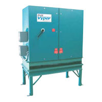
Frick Vyper 752 Installation Operation & Maintenance (76 pages)
Brand:
Frick
| Category:
Industrial Equipment
| Size: 2 MB
Table of Contents
Table of Contents
2
Preface
4
Introduction
4
Job Inspection
4
Transit Damage Claims
4
Figure 1 - Vyper ™ Data Plate
5
Unit Identification
5
Vyper ™ Model Numberdefinitions/Nomenclature
5
Model Descriptions
6
HP Model Descriptions
6
Vyper Pre-Installation Site Check List
7
Vyper Pre-Operation Site Check List
7
Pre-Startup Inspection
8
Vyper System Overview
9
Vyper Component Description
9
Figure 2A - Vyper ™ Elementary Wiring Diagram
10
Figure 2B - Vyper ™ Elementary Wiring Diagram
11
Harmonic Filter
12
Figure 3 - VSD Input Current Without Harmonic Filter
13
Figure 4 - VSD Input Current with Harmonic Filter
13
Figure 5A - Harmonic Filter Elementary Wiring Diagram
14
Figure 5B - Harmonic Filter Elementary Wiring Diagram
15
Current Limits
16
Electrical Limits
16
General Operation Description
16
Input Short Circuit Limits
16
Table 1 - Supply Voltage Requirements
16
Table 2 - Operating Voltage Limits
16
Table 3 - Power Interruption Minimum Voltage Limits
16
Table 4 - Unit Current Limits
16
Table 5 - Circuit Breaker Ratings and Lug Sizes
16
Installation
17
Rigging and Handling
17
Package Mounted Units
17
Figure 6 - Vyper ™ Package Mounted on Frick RWF II 134
17
Figure 7 - Vyper ™ Cabinet and Stand
18
Remote Mounted Units
19
Environment
19
Table 6 - Ambient Temperature Operating Limits
19
Table 7 - Vyper ™ Cabinet Component Temperature Thresholds
19
Vyper Cooling Configuration
19
Vyper Cooling Loop
19
Coolant Temperature Limits
20
General Cooling System Requirements
20
Water Recommendations
20
Glycol Recommendations
20
Figure 8 - Minimum Flow Rates - GLYCOL
20
Table 8 - Entering Coolant Temperature Limits
20
Figure 10 - Pressure Drop Vs. Flow Rate
21
Figure 9 - Minimum Flow Rates - WATER
21
Heat Exchanger Pressure Drop
21
Figure 11 - Vyper ™ P&I Diagram - Noneconomized
22
Figure 12 - Vyper ™ P&I Diagram - Economized
22
Acceptable Cable Types
23
Unshielded Cable
23
Shielded Cable
23
Figure 13 - Ground Circuit
23
Fuses and Circuit Breakers
23
Grounding
23
Power Wiring
23
Control Wiring
24
Electrical Wiring Conduit
24
Power Factor Capacitors
24
Table 10 - Recommended Transformer Sizes
24
Table 9 - Digital Control Signal Wire Recommendations
24
Transformers
24
Interfacing Electrical Equipment
25
Interference with Electronicequipment
25
Pneumatic Controls
25
Soft-Start Sequence
25
System Operating Conditions
25
Figure 14 - Vyper ™ Cabinet Power and Control Entry Locations
26
Vyper ™ Power and Control Entry Locations
26
Vyper ™ Preinstallation Site Checklist
26
External Power and Control Wiring
27
Input Power Connection
27
Figure 15 - Vyper ™ Input Power Terminal Connection Lugs
27
Figure 16 - Insulation Stripped from Power Leads
27
Figure 17 - Fastening Power Leads
27
Figure 18 - Ground Connection
27
Output Power Connection (Remote Mount)
28
Output Power Connection (Package Mount)
28
Figure 19 - Vyper ™ Output Power Terminal Connection Lugs
28
Table 11 - Vyper ™ Output Power Lead Torque Specifications
28
Vyper Wiring and Wiring Diagrams
29
Quantum ™ Lx Communications Wiring
29
Figure 20 - Vyper ™ Starter, Motor, Blower, and Quantum Wiring
29
Figure 21 - Quantum ™ LX Communications Terminal Block
29
Figure 22 - Analog Board Wiring
30
Figure 23 - Temperature Control Valve Wiring
30
Motor Thermal Protection Options
31
Figure 24 - Thermistor Motor Protection Wiring
31
Figure 25 - RTD Motor Protection Wiring
31
Vyper Preoperation Site Checklist
32
Blower Motor Rotation
33
Coolant Contamination and Properties
33
Adding and Replacing Coolant
34
Figure 26 - Coolant Circulation System
34
Figure 27 - Removing the Cooling System Pipe Plug
34
Figure 28 - Hose Connected to the Heat Exchanger Drain
34
Figure 29 - Draining Coolant
34
Figure 30 - Refilling the Cooling System
35
Figure 31 - VSD Logic Board Connection J2
35
Figure 32 - Topping off the Coolant Supply
35
Figure 33 - Installing the Cooling System Pipe Plug
35
Figure 34 - VSD Logic Board Connection J2
35
Operation
36
Quantum ™ Lx Control Panel
36
Vyper Operation
36
Accessing the Vyper Setup
37
Figure 35 - Quantum ™ LX Operating Status Screen
37
Figure 36 - Quantum ™ LX Session Screen
38
Figure 37 - Quantum ™ LX Operating Status Screen
38
Setting User Level
38
Configuring Compressor Operation
39
Figure 38 - Quantum ™ LX Compressor Configuration Screen
39
Figure 39 - Communications Screen
40
Programming Vyper™ / Quantum™Lx Communications
40
Table 12 - Comm1 Setpoints
40
Figure 40 - PID Setup Screen
41
Programming Pid Setup
41
Table 13 - PID Channel #5 Setpoints
41
Figure 41 - Operating Values Menu
42
Figure 42 - Pulldown for Vyper Screen
42
The Vyper and Harmonic Filter Screens
42
Figure 43 - Vyper™ Screen
43
Table 14 - Binary Parameter Indicator Status
43
Vyper Screen Setpoints
43
Figure 44 - Harmonic Filter Screen
44
Harmonic Filter Screen
44
Figure 45 - Low Motor Amps
45
Figure 46 - Motor Screen
45
Programming the Motor Screen
45
Table 15 - Applied Motor FLA Calculation
45
Table 16 - High Motor Amps Safety Calculation Table
45
Figure 47 - High Motor Amps
46
Figure 48 - Ex.1 Motor Amps Safety Calculation Table
46
Figure 49 - Ex. 1 Motor Amp Setpoint Calculations (Table A)
46
Figure 50 - Ex. 2 Motor Amps Safety Calculation Table
46
Figure 51 - Ex.2 Motor Amp Setpoint Calculations (Table B)
46
High Motor Amp Limit Examples
46
Table 17 - High Motor Amp Setpoint Calculations (Table A)
46
Table 18 - High Motor Amp Setpoint Calculations (Table B)
46
Figure 52 - Ex. 3 Motor Amps Safety Calculation Table
47
Figure 53 - Ex. 3 Motor Amp Setpoint Calculations (Table A)
47
Figure 54 - Ex. 4 Motor Amps Safety Calculation Table
47
Figure 55 - Ex. 4 Motor Amp Setpoint Calculations (Table A)
47
Figure 56 - Motor Screen VFD Setpoints
47
VFD Setpoints
47
Capacity Control Setpoints
48
Figure 57 - Motor Screen Capacity Control Setpoints
48
Figure 58 - Example 1 VFD and Capacity Control Setpoints
49
Suggested VFD and Capacity Control Settings
49
Figure 59 - 5:1 Turndown Suggested Control Strategy
50
Figure 60 - Example 2 VFD and Capacity Control Setpoints
50
Compressor Safeties Screen
51
Figure 61 - Compressor Safeties Screen
51
Figure 62 - 2:1 Turndown Suggested Control Strategy
52
Figure 63 - Example 2 VFD and Capacity Control Setpoints
52
Capacity Control Setpoints Screen
53
QUANTUM Lx PANEL SETUP
37
Figure 64 - Capacity Control Setpoint Screen
53
Figure 65 - Vyper Logic Board
53
Figure 66 - Logic Board SW3
53
Vsd Logic Board Setup
53
Figure 67 - Vyper Logic Board
54
Figure 68 - FLA Trim Pot
54
Figure 69 - Job FLA on the Vyper Screen
54
Motor Rotation
54
Setting the Job Fla
54
Table 19 - Limit Calculations
54
Figure 70 - Control Logic Board
55
Figure 71 - Filter Logic Board
55
Maintenance
56
Normal Maintenance Operations
56
Replacement of the Vyper Power Module
56
Standard Maintenance
56
Figure 72 - Power Module Screw Tightening Sequence
57
Replacement of the Vyper ™ Harmonic Filter Power Module
57
Figure 73 - Logic Board Test Button
58
Frequently Asked Questions
58
Vyper Alarms / Shutdowns
59
Overview
59
Frick Vyper Fault Code List
59
Table 20 - Fault Code List
59
Fault Codefault Code Descriptions
60
Index
72
Advertisement
Advertisement
Related Products
Frick Vyper 700
Frick Vyper 572
Frick Vyper 912
Frick Vyper 305
Frick Vyper 254
Frick Vyper 437
Frick Vyper 362
Frick AcuAir
Frick IDSC
Frick IDSC2
Frick Categories
Control Panel
Air Compressor
Industrial Equipment
Compressor
Air Conditioner
More Frick Manuals
Login
Sign In
OR
Sign in with Facebook
Sign in with Google
Upload manual
Upload from disk
Upload from URL