Table of Contents
Advertisement
Quick Links
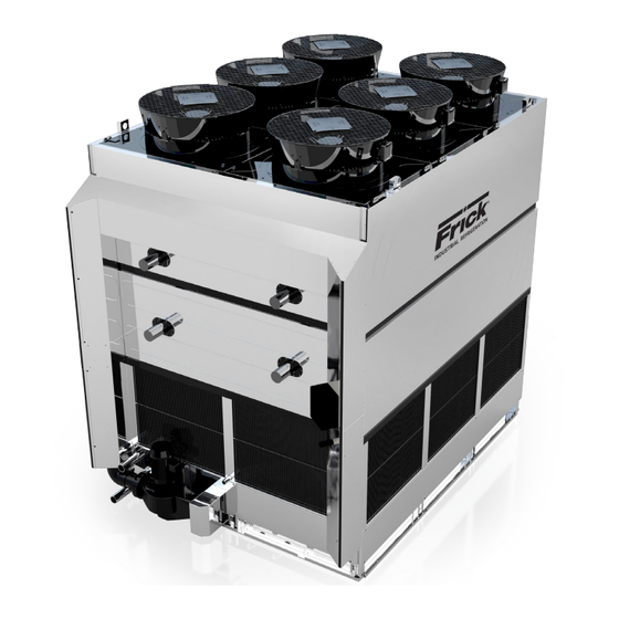
Stainless Steel Evaporative Condenser
This manual contains rigging, assembly, start-up, and maintenance
instructions. Read thoroughly before beginning installation. Failure
to follow these instructions may result in personal injury or death,
damage to the unit, or improper operation.
Check www.FrickCold.com for the latest version of this publication.
Form 140.010-IOM (NOV 2019)
INSTALLATION - OPERATION - MAINTENANCE
File:
Replaces:
Dist:
IDSC
SERVICE MANUAL - Section 140
140.010-IOM (APR 2018)
3, 3a, 3b, 3c
Advertisement
Table of Contents

Related Manuals for Frick IDSC


Summary of Contents for Frick IDSC
- Page 1 Replaces: 140.010-IOM (APR 2018) Dist: 3, 3a, 3b, 3c IDSC Stainless Steel Evaporative Condenser This manual contains rigging, assembly, start-up, and maintenance instructions. Read thoroughly before beginning installation. Failure to follow these instructions may result in personal injury or death, damage to the unit, or improper operation.
-
Page 2: Table Of Contents
140.010-IOM (NOV 2019) IDSC EVAPORATIVE CONDENSERS Page 2 INSTALLATION - OPERATION - MAINTENANCE Contents Operation General information Pre-start up inspection ........... 25 Safety instructions ............3 General ............... 25 Warranty statement ............3 Cleaning ..............25 Terminology ..............4 Start-up ..............25 Installation Cold weather operation........... -
Page 3: General Information
FRICK warrants the product to be free from defects in workmanship and materials under normal usage for a peri- Personal protective equipment must be worn at all od of 24 months from the date of purchase (the “Warranty... -
Page 4: Terminology
INSTALLATION - OPERATION - MAINTENANCE FRICK assumes no responsibility for repairs to a product by others and used as part of or in connection with FRICK sustaining damages resulting from user modifications, at- products, carry only the warranty of the manufacturer tachments to the product, misuse, alteration or negligent thereof. - Page 5 Electric heaters: Electric immersion heaters to ensure Coil section: An assembly comprised of the heat exchange the basin water does not freeze. Basin water temperature coil(s), tube sheets (IDSC only), casing, and any other maintained is approximately +40°F. structural members required.
- Page 6 140.010-IOM (NOV 2019) IDSC EVAPORATIVE CONDENSERS Page 6 INSTALLATION - OPERATION - MAINTENANCE This page intentionally left blank...
-
Page 7: Location Layout
IDSC EVAPORATIVE CONDENSERS 140.010-IOM (NOV 2019) INSTALLATION Page 7 Installation • Place the unit so that it can be monitored and con- trolled from all sides at all times. • Ensure that sufficient space is provided for maintenance. • Ensure that all liquid-carrying components, connec-... -
Page 8: Equipment Layout
140.010-IOM (NOV 2019) IDSC EVAPORATIVE CONDENSERS Page 8 INSTALLATION Table 1: IDSC configurations and air inlet and basin heights (in.) Unit Single unit Dual end to end Dual side by side Quad unit Size Inlet louver Basin Inlet louver Basin height... - Page 9 IDSC EVAPORATIVE CONDENSERS 140.010-IOM (NOV 2019) INSTALLATION Page 9 ll/one unit Two walls/two units Figure 6: One wa Figure 8: Table 3: One wall/one unit Table 5: One wall/two units Unit configuration Unit Unit configuration Unit C1 and C2 length (ft)
-
Page 10: Support Structure
3/4 in. Table 7: Three walls/single and multiple units diameter bolts. Refer to the FRICK unit certified drawing Unit configuration Unit for the bolt hole locations. -
Page 11: Receiving And Inspection
IDSC EVAPORATIVE CONDENSERS 140.010-IOM (NOV 2019) INSTALLATION Page 11 Table 8c: IDSC steel support dimensions, dual cell NOTICE arrangements (side-to-side) Refer to the submittal package for specific unit infor- Model mation. IDSC 0812... — — IDSC 2412... 23 ft, 10 in. -
Page 12: Basin Section
140.010-IOM (NOV 2019) IDSC EVAPORATIVE CONDENSERS Page 12 INSTALLATION Figure 14: Upper casing section rigged Figure 17: Nuts on shipping support Figure 15: Basin section rigged Figure 18: Basin shipping support nut removal Secure 4 screw pin shackles through each of the 4 lifting lugs. - Page 13 IDSC EVAPORATIVE CONDENSERS 140.010-IOM (NOV 2019) 43° INSTALLATION Page 13 120.0" 10'-0" Figure 20: Lifting basin section with spreader bar NOTICE 94.9" 7'-10.9" Spreader bar must traverse the full width of the unit, not the length. Incorrect size and use of the spreader...
- Page 14 140.010-IOM (NOV 2019) IDSC EVAPORATIVE CONDENSERS Page 14 INSTALLATION Figure 22: Upper section of the unit - lifting guidelines 120 in. 120.0 120 in. 120.0 51° 51° 49° 49° (10 ft) (10 ft) ( 10' ) ( 10' ) 109.0 109 in 113.9...
-
Page 15: Upper Casing Section
IDSC EVAPORATIVE CONDENSERS 140.010-IOM (NOV 2019) INSTALLATION Page 15 UPPER CASING SECTION Figure 25: Lifting upper casing with spreader bar Remove all four screws from each plate that holds the shipping support structure to the unit. This way when the unit is lifted off the truck it also lifts off the shipping sup- port structure. - Page 16 140.010-IOM (NOV 2019) IDSC EVAPORATIVE CONDENSERS Page 16 INSTALLATION See Figures 27 to Figure 31 for vertical dimension re- Figure 28: 18 ft long unit quirements for lifting the top section of the unit with two spreader bars. NOTICE Minimum recommended sling Minimum recommended sling 49°...
- Page 17 IDSC EVAPORATIVE CONDENSERS 140.010-IOM (NOV 2019) INSTALLATION Page 17 Figure 29: 8.5 ft wide unit Figure 31: 12 ft wide unit Minimum recommended Minimum recommended sling length 10 ft long sling length 10 ft long 48° 57° Ref. Ref. Minimum recommended...
-
Page 18: Offloading And Assembly
4. Secure basin section of unit to the support structure with suitable 3/4 in. diameter bolts (not provided). • Use all of the bolt holes to secure the unit to the support structure. For bolt hole locations, see FRICK unit certified drawing. 5. Prevent stresses on the unit: •... -
Page 19: Connection Joint
IDSC EVAPORATIVE CONDENSERS 140.010-IOM (NOV 2019) INSTALLATION Page 19 Figure 36: Casing installed NOTICE There is already a clearance “gap” designed between the polyvinyl chloride (PVC) riser pipe in the basin section and upper section. Take care when lifting the... -
Page 20: Installing Inlet Louvers
140.010-IOM (NOV 2019) IDSC EVAPORATIVE CONDENSERS Page 20 INSTALLATION Figure 38: Louvers and supports REMOVING INLET LOUVERS 1. Grab the inlet louver pattern. 2. Slide the inlet louver straight up to release the bottom of the inlet louver from the inlet louver opening. -
Page 21: Piping
MSPs are supplied, one main power cable needs to be run to the non-fused disconnect. PIPING All field piping external to the IDSC unit must be supported NOTICE and anchored separately. External loads must not be placed on the unit connections. -
Page 22: Electrical Data
140.010-IOM (NOV 2019) IDSC EVAPORATIVE CONDENSERS Page 22 INSTALLATION ELECTRICAL DATA NOTICE Water distribution pump The water distribution pump is not factory wired and See the pages below for generic schematics for EC requires field wiring. Motors. NOTICE EC motors A GMM controller is included as standard on all models Do not use VFDs on water distribution pump motors. - Page 23 IDSC EVAPORATIVE CONDENSERS 140.010-IOM (NOV 2019) INSTALLATION Page 23 Figure 44: Basin heaters - generic schematic...
- Page 24 140.010-IOM (NOV 2019) IDSC EVAPORATIVE CONDENSERS Page 24 INSTALLATION Figure 45: Electrical schematic for EC motor (generic)
-
Page 25: Operation
GENERAL float for basin water level adjustment is delivered pre- • All IDSC units must only be installed, operated, main- assembled. Set the circular float height to a maximum tained, and repaired by trained, experienced, and quali- water level of 14 1/4 in. a bove the lowest point in the fied personnel. -
Page 26: Cold Weather Operation
8. For remote sump applications and where the water electronic water level controller. distribution pump is not supplied by FRICK, install a globe valve in the water pump discharge line. Adjust •... -
Page 27: Extended Shutdown
Page 27 COLD WEATHER OPERATION NOTICE When operating the IDSC unit at low ambient tempera- tures above freezing, the control logic matches that of Immersion basin heaters do not prevent the residual the summer operation. The water distribution pump runs... - Page 28 140.010-IOM (NOV 2019) IDSC EVAPORATIVE CONDENSERS Page 28 OPERATION This page is intentionally left blank...
-
Page 29: Maintenance
IDSC EVAPORATIVE CONDENSERS 140.010-IOM (NOV 2019) MAINTENANCE Page 29 Maintenance Table 9: Inspection and maintenance frequencies Type of Action step Start- Monthly Quarterly Annually Shutdown action Inspect the general condition of units Clean the basin strainer Clean and flush the cold water basin... -
Page 30: Detailed Description Of Maintenance Requirements
140.010-IOM (NOV 2019) IDSC EVAPORATIVE CONDENSERS Page 30 MAINTENANCE DETAILED DESCRIPTION OF MAINTENANCE Figure 50: Detaching drift eliminator pattern REQUIREMENTS INLET LOUVER REMOVAL See Inlet louvers for instructions on how to remove the inlet louvers in order to access the cold water basin and basin strainer. -
Page 31: Cold Water Basin
50 psig. The IDSC unit is supplied with a mechanical make-up Figure 54: Spray nozzle, close-up valve, as standard, or an electronic water level controller, as an option. -
Page 32: Water Distribution Pump
High pressure water or steam must never be used to through the fan section. clean the PVC components within the IDSC unit for example, drift eliminators, inlet louvers, water distri- However, only pure water evaporates which means that bution piping and the spray nozzles. -
Page 33: Water Treatment Guidelines
IDSC units. An automatic conductiv- Metal corrosion occurs as a result of galvanic action at a ity controller is recommended to reduce water waste and negatively charged pole, or site on the metal surface. - Page 34 IDSC units, and the guidelines provided above. must be included in the maintenance schedule. The water 2.
- Page 35 IDSC EVAPORATIVE CONDENSERS 140.010-IOM (NOV 2019) MAINTENANCE Page 35...
- Page 36 Supersedes: Form 140.010-IOM (2018-04) 100 Cumberland Valley Avenue Subject to change without notice Waynesboro, PA 17268-1206 USA Published in USA • 11/19 • PDF Phone: 717-762-2121 • FAX: 717-762-8624 www.johnsoncontrols.com/FRICK © 2019 Johnson Controls Int’l PLC - ALL RIGHTS RESERVED...
Need help?
Do you have a question about the IDSC and is the answer not in the manual?
Questions and answers