Table of Contents
Advertisement
Quick Links
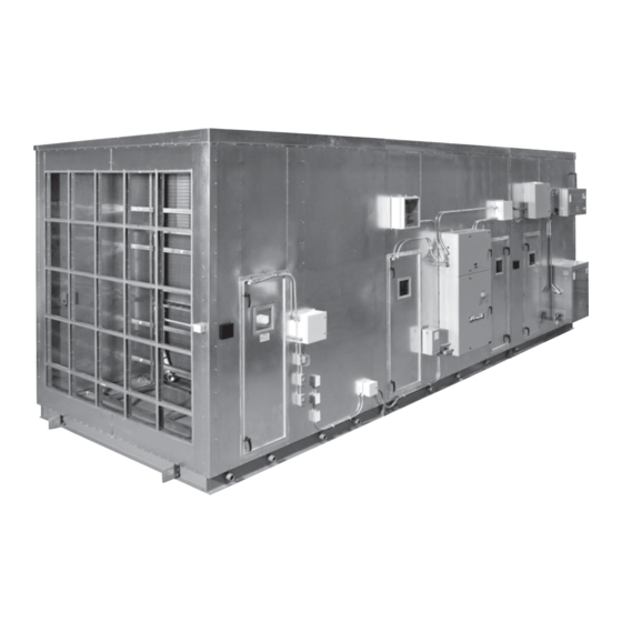
AcuAir
Hygienic Air Units
THIS MANUAL CONTAINS RIGGING, ASSEMBLY, START-UP,
AND MAINTENANCE INSTRUCTIONS. READ THOROUGHLY
BEFORE BEGINNING INSTALLATION. FAILURE TO FOLLOW THESE
INSTRUCTIONS COULD RESULT IN DAMAGE OR IMPROPER
Please check www.johnsoncontrols.com/frick for the latest version of this publication.
Form 210.100-IOM (JUL 2018)
INSTALLATION - OPERATION - MAINTENANCE
File:
Replaces:
Dist:
OPERATION OF THE UNIT.
SERVICE MANUAL - Section 210
210.100-IOM (JUL 2017)
3, 3a, 3b, 3c
®
Advertisement
Table of Contents

Related Manuals for Frick AcuAir


Summary of Contents for Frick AcuAir
- Page 1 Hygienic Air Units THIS MANUAL CONTAINS RIGGING, ASSEMBLY, START-UP, AND MAINTENANCE INSTRUCTIONS. READ THOROUGHLY BEFORE BEGINNING INSTALLATION. FAILURE TO FOLLOW THESE INSTRUCTIONS COULD RESULT IN DAMAGE OR IMPROPER OPERATION OF THE UNIT. Please check www.johnsoncontrols.com/frick for the latest version of this publication.
- Page 2 NO external wiring is allowed to be run through the micro panel. All wiring must be in accordance with Johnson Controls-Frick's published specifications and must be performed ONLY by qualified Johnson Controls-Frick personnel. Johnson Controls-Frick will not be responsible for damages/problems resulting from improper connections to the controls or application of improper control signals.
-
Page 3: Table Of Contents
ROOF RECONNECT FINISH ........19 PIEZOMETER ............... 46 INSULATION OF THE BASE RECONNECT SEAM OF AN RECOMMENDED MONTHLY SERVICE ......46 ACUAIR FOOD GRADE OR SANITARY SERIES UNIT ..21 MAINTENANCE INTERVALS ..........47 FOAM KIT 15 USE GUIDELINES RECOMMENDED MAINTENANCE INTERVALS ....47 ACUAIR UNIT BASE RECONNECT INSULATION ..... -
Page 4: Introduction
Please read the complete manual Never open an access door while air unit is in operation. prior to installing, operating, or servicing the equipment. WARRANTY NOTICE For Warranty Support with the Frick AcuAir unit, contact Frick Service at 717-762-2121. - Page 5 ACUAIR HYGIENIC AIR UNITS 210.100-IOM (JUL 2018) ® INSTALLATION - OPERATION - MAINTENANCE Page 5 1.25 1.50 DANGER DISCONNECT AND LOCKOUT POWER BEFORE SERVICE CONTACT WITH MOVING PARTS CAN CAUSE PERSONAL INJURY OR PROPERTY DAMAGE PRIOR TO OPERATION SECURE THIS ACCESS...
-
Page 6: Preinstallation Requirements
® Fans – All fan covers, guards, and shaft retainers (if any) properly anchored field piping. NO field piping is to be must be in place before applying power to an AcuAir system. ® supported by the AcuAir system itself. - Page 7 3. The minimum distance from any electrical enclosure to to any object. an object is 48". The installation of the AcuAir unit must be in accordance with the codes of the authorities having 6. As with any large equipment placement consideration of jurisdiction.
-
Page 8: Installation
Extra Fan Belts (If Ordered) date the AcuAir unit is placed into active duty. For optimal Installation and Start-Up Manual sensor life involving storage: Lifting Lugs •... - Page 9 THAN THE UNIT WIDTH TO PREVENT DAMAGE WARNING TO THE HOUSING When lifting individual AcuAir sections, weight may not be evenly distributed causing the section to be unbal- anced or top heavy. To prepare for safely lifting the air unit, estimate the approximate center of gravity.
-
Page 10: Support Structure Information
The weight the support structure must support and The AcuAir unit must be secured to the Support structure. It the anchoring requirements will vary with live loads (expected is the installer’s responsibility to be sure the unit is secured snow/ice buildup) seismic, and wind loading. -
Page 11: Section Reconnect Ship Loose Items
(Required on units 150" or wider) Figure 7 - Generic Roof Curb Support SECTION RECONNECT SHIP LOOSE ITEMS INSTALLATION TOOLS • AcuShield Roof Coating To complete the installation of an AcuAir system, the ® • Joint Sealing Caulk following tools are required: •... -
Page 12: General Split Unit Reassembly
2. Curb must be level (shim if required). Shims (at fractions • AcuAir units are assembled in one piece in our factory and of inch) should be placed at intervals no greater than 5 feet split prior to shipping. -
Page 13: Performance Grade Connections
HARDWARE NOT SHOWN THIS SIDE FOR CLARITY .75 HEX BOLT .75 HEX NUT (USE FROM LIFTING LUG) (USE FROM LIFTING LUG) .75 SPLIT WASHER .75 FLAT WASHER .75 FLAT WASHER Figure 9 – Base Assembly Attachment - Relates to AcuAir Performance Series Unit Only... -
Page 14: Reconnection Attachment And Sealing Procedure
LINER .25-20 X .75 HEX BOLT WITH .25 FLANGED LOCKNUT (SUPPLIED BY JOHNSON CONTROLS) INTERNAL RECONNECT Figure 10 – Cross Section Of Split Wall Assembly - AcuAir Performance Series Only RECONNECTION ATTACHMENT AND SEALING PROCEDURE (See Figure 11) .25” MIN DIA CONTINUOUS 1. -
Page 15: Insulation Of The Base Reconnect Seam Of An Acuair Performance Series Unit
PRIOR TO REASSEMBLING INTERNAL RECONNECT HOUSING (AcuAir Performance Series Only) RECONNECT, HOUSING, AND HARDWARE NOT SHOWN THIS SIDE FOR CLARITY Foam Injected From Underneath Figure 12 – Foam Injection Underneath Base Assembly Attachment - Relates to AcuAir Performance Series Unit Only... - Page 16 SHIPPING SPLIT DETAIL A Acceptable Polyurethane Caulking: Manus-bond, Gray, P/N 013-02966-001 Manus-bond, Champagne, P/N 013-03317-220 Bostik, Gray, P/N 013-03318-170 DETAIL B Bostik, Champagne, P/N 013-03319-170 CAULK SHIPPING SPLIT COVER Figure 13 – Split Reassembly Procedure For AcuAir Performance Series Units Only...
-
Page 17: Acuair Performance Series Roof Sealant Procedure
ACU-SHIELD ROOF COATING * 3" MIN CAULKING (PROVIDED) ROOF HOUSING SPLIT * Provided with ship loose items in fan section (see table in Section, "Receiving & Inspection"). Figure 14 – Outdoor Split Roof Sealant Procedure - AcuAir Performance Series Only... -
Page 18: Food Grade And Sanitary Connections
Reference either the lower left or the lower right views of Figure 15. It may be advantageous to locate the first AcuAir unit section in its final position and attach it to the support 7. -
Page 19: Acuair Food Grade Or Sanitary Series Roof Reconnect Finish
OF CAULK ALONG INNER SEAM Figure 16 – Cross Section Of Split Wall Assembly EXTERNAL RECONNECT POLYURETHANE .25 DIA CAULK CONTINUOUS BEAD OF CAULK BASE RECONNECT FLANGE Figure 17 – Multi-Section Reconnect Sealing On AcuAir Food Grade and Sanitary Series Units... - Page 20 Acceptable Polyurethane Caulking: Manus-bond, Gray, P/N 013-02966-001 Manus-bond, Champagne, P/N 013-03317-220 Bostik, Gray, P/N 013-03318-170 Bostik, Champagne, P/N 013-03319-170 DETAIL B CAULK SHIPPING SPLIT COVER Figure 18 – Split Reassembly Procedure For AcuAir Food Grade and Sanitary Series Units Only...
-
Page 21: Insulation Of The Base Reconnect Seam Of An Acuair Food Grade Or Sanitary Series Unit
When filling the reconnect seam from the top (inside the cavity prior to installing the reconnect split cover strip, or AcuAir unit), it may be advisable to cover the bottom of the from underneath the unit provided the reconnect joint is not opening with duct tape to prevent the foam from dropping positioned directly over a support structure cross member. -
Page 22: Foam Kit 15 Use Guidelines Acuair Unit Base Reconnect Insulation
Page 22 INSTALLATION FOAM KIT 15 USE GUIDELINES ACUAIR UNIT BASE RECONNECT INSULATION Always review and follow the directions provided in your foam kit. The below instructions are a general overview, meant to Accompany the reference photos. Ensure you follow all safety Precautions including wearing protective eyewear and gloves. -
Page 23: Acuair Fresh Air Intake Plenum
4. The AcuAir unit is provided with plenum alignment tabs and attachment clips to assist with correctly positioning the plenum assembly and holding it in position as it is secured to the air unit. - Page 24 Figure 28 - Plenum Leg Attachment 11. When the plenum is plumb and level, use the screws that were provided to attach the plenum section to the AcuAir unit. (The screws are shipped loose and can be found in the Figure 29 - Fresh Air Temperature Sensor Mounting blower section).
-
Page 25: Fan Hold-Down / Spring Isolator Setup
ACUAIR HYGIENIC AIR UNITS 210.100-IOM (JUL 2018) ® INSTALLATION Page 25 FAN HOLD-DOWN / SPRING ISOLATOR SETUP Place tubes on studs and place shoulder washer (shoulder up) on studs. Place one (1) nut on each stud and tighten it on (OPTIONAL) shoulder washer. -
Page 26: Condensate Drain Trap Sizing
To design the drain traps, reference Figure 31 as well as the total static pressure (TSP) associated with the main fan and motor as indicated on the applicable AcuAir data drawing. For AcuAir drain and system piping information and recommendations, refer to AcuAir white paper, 210.200-WP6. -
Page 27: Duct Connections
(PSIG). It is the contractor’s and/or customer’s responsibility It is recommended that all duct connections to the AcuAir unit to provide controls and reliefs within the refrigeration system be insulated to minimize condensation. -
Page 28: Weather Hood Connection Direct To The Acuair Fresh Air Opening
HYGIENIC AIR UNITS ® Page 28 INSTALLATION WEATHER HOOD CONNECTION DIRECT TO THE ACUAIR FRESH AIR OPENING POLYURETHANE CAULKING (See Figures 35 and 36) 1. Apply polyurethane caulking to the flange of the hood. 2. Align the hood over the opening. Check for adequate clear- ance to doors and other openings on the air-handling unit. - Page 29 ACUAIR HYGIENIC AIR UNITS 210.100-IOM (JUL 2018) ® INSTALLATION Page 29 Material Required 3. Carefully cut correct hole size for the application in panel, ensuring cuts on both sides line up and a smooth clean cut is • Neoprene grommet, 2½”, 3¼”, 4½” or 5½" as required.
-
Page 30: Filter Installation Table Of Contents
Page 30 INSTALLATION FILTER INSTALLATION TABLE OF CONTENTS ACUAIR MATRIX: KOCH FILTERS AND KOCH FRAMES / LATCHES .................. 30 INSTALLATION OF 4” PLEATED PANEL FILTERS ....................... 34 INSTALLATION OF SH SINGLE HEADERED RIGID FILTERS ....................34 INSTALLATION OF A DH DOUBLE HEADERED RIGID FILTER ..................... 34 INSTALLATION OF HEPA FILTERS .............................36... -
Page 31: Acuair Single Filter Application (Non-Hepa)
KOCH 102 701 023 24" X 24" X 4" 102-701-031 MP XL8-HC KOCH 102 701 031 XL8-HC Filters are AcuAir Standard Supply for Prefilters MERV 11, MP XL11 High Capacity 12" X 24" X 4" 120-500-023 MP XL11-HC KOCH 102 500 023 24"... - Page 32 HYGIENIC AIR UNITS ® Page 32 INSTALLATION Multi-Pleat Multi-Pleat XL8 HC XL11 HC ACUAIR SINGLE FILTER APPLICATION (NON-HEPA FILTER) cont. † Width x Height x Depth Koch Part Number Koch Model AcuAir Part Number ‡ MERV 13 Rigid 12" X 24" X 12" DH...
-
Page 33: Hepa Filter Application
HEPA FILTER APPLICATION Description - H x W Koch Part Number Koch Model AcuAir Part Number AcuAir HEPA Filter Frames 24" X 24"-14 ga. Galvanized 122-508-2424 Galv. HEPA Frame KOCH 122 508 2424 12" X 24"-14 ga. Galvanized 122-508-1224 Galv. -
Page 34: Installation Of 4" Pleated Panel (Pre)Filters
210.100-IOM (JUL 2018) ACUAIR HYGIENIC AIR UNITS ® Page 34 INSTALLATION INSTALLATION OF 4” PLEATED PANEL Installation of Latches (PRE)FILTERS 1. Insert the straight end of the latch between the two (2) knockouts furthest from the corner. These instructions are for installing 4" panel filters into type 8 holding frames. - Page 35 ACUAIR HYGIENIC AIR UNITS 210.100-IOM (JUL 2018) ® INSTALLATION Page 35 DO NOT USE! USE THESE! Figure 40 – Correct Use of Knockouts Installation of Spring Latches Figure 42 – Frame with 4 latches installed. 1. Insert the straight end of the latch between the knockouts furthest from the corner.
-
Page 36: Hepa Filters
Most pinhole leaks and bypass holes can be repaired in the field. If unprotected HEPA filters are placed on dirty surfaces prior to installing them in the AcuAir unit filter frames they become subjected to unnecessary contamination and possibly long term hygienic compromise. -
Page 37: Start-Up
AcuAir system. Filters NOTICE The AcuAir unit is supplied with all filter racks in place. The filters and filter clips are shipped separately, direct from the filter supplier. Once the unit is completely installed and... -
Page 38: Start-Up After Prolonged Shutdown
6. Verify the voltage and current of all three legs of the fan motors. The current should not exceed the rated service factor. Figure 45 - AcuAir Direct Fired Gas Burner After prolonged shutdowns, the motor insulation should be checked with a Megger Tester prior to restarting the motors. -
Page 39: Maintenance
Components of the AcuAir unit should also be part of the daily coil tubes and piping. operational checks conducted of the equipment on site. In... -
Page 40: Filter Maintenance
– repair if the possibility of air or water door switches by either of two methods: through unsealed leakage exists. conduit ends and flexible conduit pigtails prior to the AcuAir FILTER MAINTENANCE unit factory wiring being reconnected on site or by moisture... -
Page 41: Unit Cleaning And Sanitation
Addressing A Light Coating Of White Rust Also Known As Wet Storage Stain UNIT CLEANING AND SANITATION Occasionally AcuAir units may arrive on site with patches of The AcuAir hygienic unit requires frequent and thorough visible zinc hydroxide deposits. In other cases white patches of cleaning. -
Page 42: Fan Bearing Lubrication
210.100-IOM (JUL 2018) ACUAIR HYGIENIC AIR UNITS ® Page 42 MAINTENANCE FAN BEARING LUBRICATION FAN SEGMENT-FAN MOTOR Standard fan configurations ship with fan bearings factory Keep the motor clean, dry and properly lubricated at all times. lubricated (ready for start-up). The fan should be turned off... -
Page 43: Lubrication
ACUAIR HYGIENIC AIR UNITS 210.100-IOM (JUL 2018) ® MAINTENANCE Page 43 Lubrication CAUTION Motor Bearing Lubricant - Bearing grease will lose its To avoid damage to motor bearings, grease must be kept lubricating ability over time. The lubricating ability of grease free of dirt. -
Page 44: Inspecting V-Belts And Sheaves
210.100-IOM (JUL 2018) ACUAIR HYGIENIC AIR UNITS ® Page 44 MAINTENANCE INSPECTING V-BELTS AND SHEAVES of contact. Ordinarily, a misalignment of more than one-half of one degree (one-eighth inch in one foot) will adversely affect Before a new set of V-belts are installed, inspect the condition belt life. - Page 45 ACUAIR HYGIENIC AIR UNITS 210.100-IOM (JUL 2018) ® MAINTENANCE Page 45 ALIGNMENT USING STRAIGHTEDGE (A) Straightedge touching sheaves at points indicated by arrows. ALIGNMENT USING STRING (B) Cord tied to shaft Cord touching sheaves at points indicated by arrows. Figure 52 – Sheave Alignment 4.
-
Page 46: Operating And Maintenance Instructions For Piezometer
RECOMMENDED MONTHLY SERVICE and replace with a comparable type of tubing. Along with daily logs and weekly inspections, Johnson Controls-Frick recommends that the unit undergo a thorough NOTICE monthly inspection. The monthly inspection should include but not limited to the following areas as indicated in the... -
Page 47: Maintenance Intervals
® due to “forgotten” spare parts order placement. maintain an inventory of spare parts for the AcuAir air unit. By maintaining this inventory of spare parts, change-out The type and recommended stock level for recommended part requirements can be immediately satisfied during preventative is listed in the order specific documentation provided after maintenance inspections. -
Page 48: Troubleshooting
210.100-IOM (JUL 2018) ACUAIR HYGIENIC AIR UNITS ® Page 48 MAINTENANCE TROUBLESHOOTING Symptom Probable causes and Corrections Motor doesn’t start Check MOA module to see if in AUTO (green light if on/red light if fuse is blown) Check blower door switch... -
Page 49: Acuair Factory Start-Up Assistance
Factory start-up assistance should be requested at least two weeks prior to the start-up date. A request for start-up assistance is initiated by completing the AcuAir Prestart-up Checklist. E-mail, fax or mail the checklist to the factory per the instructions noted at the bottom of the checklist. Once the checklist is received, a factory representative will work with you to determine the best available date that a factory technician can be at the job site. -
Page 50: Acuair Air Handler Prestart-Up Checklist
ACUAIR AIR HANDLER PRESTART-UP CHECKLIST Name of Installing Contractor ______________________________ Unit Tag # _________________________________________ Qualified Technician’s Name: ______________________________ Unit Model # ______________________________________ Frick Sales Order # _______________________________________ Unit Serial # _______________________________________ Job Name _______________________________________________ Job Site Location ________________________________________ Job Site Contact and Phone # _____________________________... - Page 51 ACUAIR HYGIENIC AIR UNITS 210.100-IOM (JUL 2018) ® INSTALLATION - OPERATION - MAINTENANCE Page 51 Index Acu-Shield Roof Coating, 19 heater, 38 thermal expansion, 26 airborne contaminants, 39 HEPA, 8 tools, 11 air-leakage, 27 HEPA FILTERS, 30 Troubleshooting, 48 Alignment, 44...
-
Page 52: Appendix
Supersedes: 210.100-IOM (2017-07) 100 Cumberland Valley Avenue Subject to change without notice Waynesboro, PA 17268-1206 USA Published in USA • 09/18 • PDF Phone: 717-762-2121 • FAX: 717-762-8624 www.johnsoncontrols.com/frick © 2018 Johnson Controls Int'l PLC - ALL RIGHTS RESERVED APPENDIX... - Page 53 A. Equipment not “started” within six (6) months of leaving cies. The logs shall be sent to the Johnson Controls AcuAir the Johnson Controls factory. Service Department in Waynesboro, PA.
- Page 55 May 2017 (Logo) Long Term Storage Requirements Field Preparation of Air Handling Units Upon completion of the long-term storage period, the standard AcuAir warranty commences. 12 MONTHS PARTS ONLY (Not to exceed 18 months from ship date.) NOTICE Failure to comply with these requirements will render any written or implied Johnson Controls warranty null and void.
- Page 56 Johnson Controls desiccant packet sized for panel. Install C.I. AcuAir Service Department. 9. AcuAir Quantum or A-B Control panel – Assure all conduit openings through the panel enclosure are completely sealed. Install desiccant packet sized for panel. Install C.I.
- Page 57 4.1 Unwrap all electrical cabinets and install new Vapor Emitters. pressure. If pressure drops more than 2 psi, the unit should (Frick BPC Part # 026-37705-000 OR 026-37706-000 be pressure tested to locate the leak; the leak should be Corrosion Inhibitor). Reseal.
- Page 58 ACUAIR AIR HANDLING UNIT PERIODIC CHECKLIST AND LOGS Job Name: ______________________________________________ Contract # ________________________________________ Date Delivered: __________________________________________ Unit Model # ______________________________________ Date of Storage Prep: ____________________________________ Unit Serial # _______________________________________ Condition of Unit Delivered: ___________________________________________________________________________________ Explain: _____________________________________________________________________________________________________ ____________________________________________________________________________________________________________ 1.0 MONTHLY...
Need help?
Do you have a question about the AcuAir and is the answer not in the manual?
Questions and answers