
Related Manuals for Turbo Air SMART 7 STI030MR404A1


Summary of Contents for Turbo Air SMART 7 STI030MR404A1
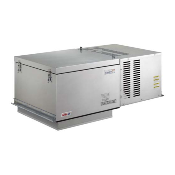
- Page 1 Turbo air Speeds Up the Pace of Innovation Part No. KUCST1307 CAREL CONTROLLER Refrigeration System Installation & Operation Manual Please read this manual completely before attempting to install or operate this equipment ! Package Unit ( TOP MOUNT )
-
Page 3: Table Of Contents
CONTENTS Safety Information …………………………………… Inspection ……………………………………………… Locating SMART 7 Package Unit…………………… Installation Procedure ………………………………… Sequence of Operation ……………………………… Controller Setting …………………………………… System Troubleshooting …………………………… Electrical Wiring Diagram……………………………... -
Page 4: Safety Information
If damaged material becomes the delivering carrier’s responsibility and it should not be returned to Turbo air unless prior approval is given to do so. Check the serial tag information with invoice. Report any discrepancies to Turbo air sales... - Page 5 Table 1. INDOOR UNIT - Medium Temperature (Air Defrost System) Ambient 95℉ Refrigerant. Matching Plug Model Capacity BTUH Voltage MOPD NEMA Weight Fig. Supplied Ref. Receptacle (Lbs) 35℉ 38℉ STI030MR404A1 3183 3380 115/1/60 R404A 5-20R STI050MR404A1 5026 5356 115/1/60 11.3 R404A 5-20R STI050MR404A2...
- Page 6 Figure A. INDOOR UNIT – Small Cabinet (Opening Size : 14.5 inch x 20.8 inch) Figure B. INDOOR UNIT – Medium Cabinet (Opening Size : 25 inch x 25 inch) Figure C. INDOOR UNIT – Large Cabinet (Opening Size : 25 inch x 38.5 inch) Figure D.
-
Page 7: Locating Smart 7 Package Unit
Locating SMART 7 Package Unit Unit Installation Requirements 1. You must ensure before unit placement on the roof of box that the structural strength of the box can withstand the weight of SMART7 equipment 2. The unit should be installed away from noise sensitive site and must have proper support for noise and vibration not to be transmitted into the building. - Page 8 Figure 1. Minimum Clearance at Installation of Unit. W = UNIT WIDTH W = UNIT WIDTH Figure 3. Two or more Unit Figure 2. One Unit...
-
Page 9: Installation Procedure
Installation procedure Indoor use only ( STI Model ) 1. Carefully check package for damages during transportation and unit after opening the package. 2. Requirements must be followed for installing location on the page of 6~7. 3. Ensure weights of units on the page of 4~5 and that structural strength of the box can withstand of the weight of the unit. - Page 10 Check before Unit Start-up. 1. Check all electrical and refrigerant connections. 2. Observe all applicable building and electrical codes when wiring. 3. Make sure power supply has correct voltage and phase for unit and is fused properly. 4. If unit is connected with a power cord, use the cord with plug to connect to power supply. If unit is not connected with a power cord, use hard wire to connect to power supply.
-
Page 11: Sequence Of Operation
Sequence of Operation. Operation of Refrigeration. 1. When switch is turned on, power is provided to the temperature control, compressor, condenser and evaporator fan motor. And they will run until the box temperature setting is reached. 2. When the box temperature reaches a setting, the compressor and condenser fan motors shut off while evaporator fan motor is working. -
Page 12: Controller Setting
Controller Setting. Carel PJEZC Electronic Controller. The most complete solution for low temperature ventilated units, with three relays for complete control of the compressor, fan and defrost functions. The three relays are included in the very compact case in the versions with 230 V or 115 V power transformer, without compromising the performance or reliability of the product. - Page 13 Once the electrical connections have been completed, simply power-up the controller to make it operative. Turbo air recommends to check that the display does not show any alarm signals (see par. Table 7), and finally set the parameters as desired (see par. Table 5,6).
- Page 14 Functions available from the keypad. On and off Switching the instrument ON : press UP for more than 3 s (when pressing the button, the display shows ON). Switching the instrument OFF : press UP for more than 3 s. The display shows the message “OFF”, alternating with the temperature measured by the set probe.
- Page 15 Manual defrost Press DOWN for more than 3 s (activated only if the temperature conditions are right). Continuous cycle Press UP+DOWN for more than 3 s (activated only if the temperature conditions are right and for easy split only when H6=0). The continuous cycle is used to maintain refrigeration active in the cabinet or cold room, regardless of the temperature inside the unit.
- Page 16 Device setup. Rapid parameter set selection (EZY) The easy controllers feature the EZY parameter which is used to quickly choose a list of parameters, with corresponding values, for the control of the refrigeration system. Table 5. SET 1 (EZY=1) – Low temperature (SET POINT : -10℉) Electric defrost Parameter Description Default...
- Page 17 Table of alarms and signals. When an alarm is activated, the display shows the corresponding message that flashes alternating with the temperature; if fi tted and enabled, the buzzer and the alarm relay are also activated. All the alarms have automatic reset (that is, they stop when the causes are no longer present), except for alarm ‘CHt’...
- Page 18 Description of the main signals and alarms. LED flashing The activation of the corresponding function is delayed by a timer, awaiting an external signal or disabled by another procedure that is already in progress. e.g. if is a continuous cycle in progress and a defrost is called, the latter will remain pending until the end of the continuous cycle, and the corresponding LED (defrost) will flash.
- Page 19 HI flashing high temperature alarm. The probe has measured a temperature higher than the set point by a value that exceeds parameter AH. • check parameters AH, Ad and A0. The alarm is automatically reset when the temperature returns within the set limits (see parameter AH). EE displayed during operation or on power-up unit parameter reading error.
- Page 20 Modifying the parameters. Parameter navigation The operating parameters, modifiable using the keypad, are divided into two types: frequent (type F) and confi guration (type C). Access to the latter is protected by password (default= 22) to prevent accidental or unauthorised modifications. Accessing the type F parameters: •...
- Page 21 WARNINGS: If no button is pressed for 60 s, all the changes made to the parameters, temporarily saved in the RAM, will be cancelled and the previous settings restored. The dAY, hr, Min parameters are not restored, as these are saved instantly when entered. If power is disconnected from the instrument before saving the settings (pressing the SET button for 3 s), all the changes made to the parameters and temporarily saved will be lost.
- Page 22 Controller Troubleshooting. The following table shows a number of anomalous situations that may occur on the various models. The most frequent causes and corresponding checks are described: Problem Cause Checks the compressor does not start (signalled by the • compressor delay set parameters c0, c1 and c2 and dd compressor LED flashing) •...
- Page 23 Listing of Controller Parameters and Settings. Defaults Codes Description Type Low temp. Med temp. password +199 PROBE PARAMETERS probe measurement stability select probe displayed select ℃/℉ (0=℃, 1=℉) flag disable decimal point flag enable probe 2 alarm (model M only) ℉...
- Page 24 ALARM PARAMETERS ℉ alarm and fan temperature diff erential ℉ low temperature alarm threshold/deviation ( AL= 0 : alarm disabled ) +250 ℉ high temperature alarm threshold/deviation ( AH= 0 : alarm disabled ) +250 low and high temperature alarm delay digital input configuration 0 : input not active 1 : exter.
-
Page 25: System Troubleshooting
System troubleshooting. Symptoms Possible causes Solution Main switch open Close switch Check electrical circuits and motor winding for shorts or grounds. Blown fuse Replace fuse after fault is corrected. Loose wiring Check all wire junctions. Tighten all terminal screws. System cable shut down Replace shutdown cable. -
Page 26: Electrical Wiring Diagram
Electrical Wiring Diagram. Diagram 1. Wiring diagram for SMART 7, Air Defrost 115V / 1Ph / 60Hz. Model : STI030MR404A1 Diagram 2. Wiring diagram for SMART 7, Air Defrost 115V / 1Ph / 60Hz. Model : STI050MR404A1... - Page 27 Diagram 3. Wiring diagram for SMART 7, Air Defrost 208~230V / 1Ph / 60Hz. Model : STI050MR404A2, STX050MR404A2 Diagram4. Wiring diagram for SMART 7, Air Defrost 208~230V / 1Ph / 60Hz. Model : STI068MR404A2 , STI075MR404A2 , STX068MR404A2 , STX075MR404A2...
- Page 28 Diagram5. Wiring diagram for SMART 7, Air Defrost 208~230V / 1Ph / 60Hz. Model : STI100MR404A2 , STI130MR404A2 , STX100MR404A2 , STX130MR404A2 Diagram6. Wiring diagram for SMART 7, Air Defrost 208~230V / 3Ph / 60Hz. Model : STI100MR404A3, STI130MR404A3, STX100MR404A3, STX130MR404A3...
- Page 29 Diagram7. Wiring diagram for SMART 7, Electric Defrost 208~230V / 1Ph / 60Hz. Model : STI022LR404A2, STX022LR404A2 Diagram8. Wiring diagram for SMART 7, Electric Defrost 208~230V / 1Ph / 60Hz. Model : STI045LR404A2 , STX045LR404A2...
- Page 30 Diagram9. Wiring diagram for SMART 7, Electric Defrost 208~230V / 1Ph / 60Hz. Model : STI055LR404A2 , STI070LR404A2 , STX055LR404A2 , STX070LR404A2 Diagram10. Wiring diagram for SMART 7, Electric Defrost 208~230V / 3Ph / 60Hz. Model : STI055LR404A3 , STI070LR404A3 , STX055LR404A3 , STX070LR404A3...
- Page 31 1250 Victoria street CARSON, CA 90746 FAX : 310-900-1008 Toll Free : 888-900-1002 (U.S.A & Canada) http://www.turboairinc.net...
Need help?
Do you have a question about the SMART 7 STI030MR404A1 and is the answer not in the manual?
Questions and answers