Sign In
Upload
Download
Add to my manuals
Delete from my manuals
Share
URL of this page:
HTML Link:
Bookmark this page
Add
Manual will be automatically added to "My Manuals"
Print this page
×
Bookmark added
×
Added to my manuals
Manuals
Brands
Case IH Manuals
Tractor
FARMALL 90C
Service manual
Case IH FARMALL 90C Service Manual
Hide thumbs
1
2
3
4
5
6
7
8
Table Of Contents
9
10
11
12
13
14
15
16
17
18
19
20
21
22
23
24
25
26
27
28
29
30
31
32
33
34
35
36
37
38
39
40
41
42
43
44
45
46
47
48
49
50
51
52
53
54
55
56
57
58
59
60
61
62
63
64
65
66
67
68
69
70
71
72
73
74
75
76
77
78
79
80
81
page
of
81
Go
/
81
Bookmarks
Advertisement
Quick Links
1
Table of Contents
2
Note to the Owner Warnings for Air Conditioning System Repair Operations
3
Personal Safety Cab Air Conditioning System
4
Basic Instructions
5
Part Identification
Download this manual
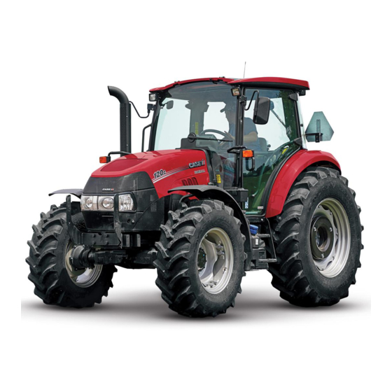
FARMALL
FARMALL
FARMALL
FARMALL
Efficient Power
Tier 4B (final)
SERVICE MANUAL
Part number 47878246
90C
®
100C
®
110C
®
120C
®
Tractor
1
edition English
st
June 2015
Previous
Page
Next
Page
1
2
3
4
5
Advertisement
Need help?
Do you have a question about the FARMALL 90C and is the answer not in the manual?
Ask a question
Questions and answers
Related Manuals for Case IH FARMALL 90C
Tractor Case IH Farmall 115U Pro EP Service Manual
(1569 pages)
Tractor Case IH 91 Series Installation Manual
Smartrax system installation (35 pages)
Tractor Case IH 93 Series Installation Manual
Smartrax system installation (35 pages)
Tractor Case IH 9370 Installation Manual
Smartrax system installation (35 pages)
Tractor Case IH 85C Service Manual
(52 pages)
Tractor Case IH FARMALL 85C Service Manual
(51 pages)
Tractor Case IH Farmall 65C Operator's Manual
(6 pages)
Tractor Case IH FARMALL 75N Service Manual
(51 pages)
Tractor Case IH FARMALL 80N Service Manual
(51 pages)
Tractor Case IH Farmall 110V Operator's Manual
(15 pages)
Tractor Case IH Farmall 95U Efficient Power Service Manual
(61 pages)
Tractor Case IH FARMALL 95A Service Manual
(10 pages)
Tractor Case IH Farmall 45A Service Manual
(51 pages)
Tractor Case IH FARMALL 110U Service Manual
(81 pages)
Tractor Case IH FARMALL 30B Service Manual
(41 pages)
Tractor Case IH FARMALL 75C Service Manual
Efficient power tractor (24 pages)
This manual is also suitable for:
Farmall 100c
Farmall 110c
Farmall 120c
Save PDF
Print
Rename the bookmark
Delete bookmark?
Delete from my manuals?
Login
Sign In
OR
Sign in with Facebook
Sign in with Google
Upload manual
Upload from disk
Upload from URL


Need help?
Do you have a question about the FARMALL 90C and is the answer not in the manual?
Questions and answers