
Related Manuals for Ryobi RA-NC1565-K


Summary of Contents for Ryobi RA-NC1565-K
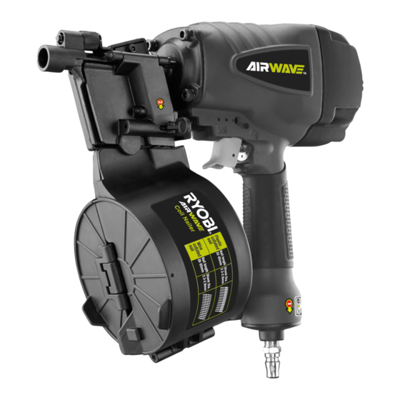
- Page 1 RA-NC1565-K AIRWAVE AIR COIL NAILER OPERATOR'S MANUAL ORIGINAL INSTRUCTIONS Important! It is essential you read the instructions in this manual before starting and operating this machine.
- Page 2 DESCRIPTION 1. Nitto style coupler 12. Hammer (not included) 22. Nail head track 2. Exhaust cap 13. Flat blade screwdriver (not 3. Air supply included) 4. Feeder cover 14. Jammed fastener 5. Feeder cover latch 15. Screw hole 6. Magazine cover 16.
- Page 3 Fig. 8 Fig. 9 Fig. 10 Fig. 11 Fig. 12 Fig. 13 Fig. 14...
- Page 4 Fig. 15 Fig. 16 Fig. 17 Quick Quick connector connector Lubricator Filter Tool compressor Cut-off valve Quick Quick coupler coupler Regulator Air hose (0-8.5 bar) Fig. 18...
-
Page 5: General Safety Rules
While using an air tool, the operator should adopt a GENERAL SAFETY RULES comfortable posture while maintaining a secure footing and avoiding awkward or off-balanced postures. The For multiple hazards, read and understand the safety instructions before installing, operating, repairing, operator should change posture during extended tasks, which can help avoid discomfort and fatigue. -
Page 6: Additional Safety Instructions For Pneumatic Power Tools
INFORMATION ON MECHANICAL IMPACT(VIBRATION) Repairs shall be carried out only by the manufacturer's authorized agents or by other experts, having due The characteristic vibration values for the fastener driving regard to the information given in the operating tool have been determined in accordance with ISO 8662- instructions. -
Page 7: Residual Risks
trigger using finger pressure. In addition, fastener driving tool is fitted with a safety yoke which enables the driving operation to be carried SYMBOLS out only after the safety yoke of the tool is pressed against a work piece, These tools are marked with an inverted triangle behind the serial number and are Safety alert... -
Page 8: Specifications
SPECIFICATIONS C-weighted sound L PC,peak =91.8 dB(A), pressure level K PC,peak =2.5 dB FASTENER Vibration according to ISO 8662-11:1999 15° coil nails, wire ah,W=11.5 m/s 2 , Vibration in the collated, K=1.5 m/s 2 handle Dia. 2.3 - 2.9 mm Nail range: INTENDED USE 38 - 65 mm... -
Page 9: Preparing The Tool For Use
WARNING WARNING Do not use this product if it is not completely assembled Always wear safety goggles or safety glasses with side or if any parts appear to be missing or damaged. Use of shields when operating tools. Failure to do so could a product that is not properly and completely assembled result in objects being thrown into your eyes resulting could result in serious personal injury. - Page 10 LOADING THE TOOL WITH FASTENERS WARNING Ensure that the pressure supplied by the compressed air system does not exceed the maximum allowable WARNING pressure of the fastener driving tool. Set the air pressure initially to the lower value of the recommended tool so that the safety yoke is not pointing towards the operator or any other person or animals.
-
Page 11: Setting The Air Pressure
The compressed air connectors of the fastener driving tool WARNING and the hoses should be protected against contamination, the ingress of coarse dust chips, sand, etc, will result in Do not use fasteners with shank diameter smaller leaks and damage to the fastener driving tool and the couplings. -
Page 12: General Maintenance
actual job. 1. Disconnect the tool from the air supply. 2. Open the feeder cover. Drive a test fastener with the air pressure set at 6.2 - 6.5 3. Remove fasteners from the tool. 4. Insert a rod into the driving mechanism. Tap the rod the lowest setting that will perform the job with consistent with a hammer to push the driver mechanism back, results. -
Page 13: Cold Weather Operation
COLD WEATHER OPERATION 7. Set the depth of drive according to the “drive depth adjustment” section in this manual. Repeat this For cold weather operation, near and below freezing, checklist before using the tool each day, or if the tool is the moisture in the air line may freeze and prevent tool dropped or damaged in any way. -
Page 14: Troubleshooting
TROUBLESHOOTING PROBLEM CAUSE POSSIBLE SOLUTION Loose screws. Tighten screws. Air leak near the top of the tool or in the trigger area. Worn or damaged O-rings or seals. Install overhaul kit. Loose screws. Tighten screws. Air leak near the bottom of the tool. -
Page 15: Parts List
PARTS LIST No. Description Description Description Description Bolt Sealing washer Piston spring seat Tray cover Pusher Circlip Circlip Spring slice Magnet Washer Adj. plate Dowel Washer O-ring 16 x 1.6 Pin 2.5 x 12 Spring Bolt Valve seat Adjusting seat Bolt M6 x 25 Bolt M4 x 16 O-ring 6.1 x 1.8... - Page 16 Techtronic Industries (Australia) Pty. Ltd. Level 1, 660 Doncaster Road Doncaster, VIC 3108, Australia Techtronic Industries New Zealand Ltd. 18-26 Amelia Earhart Avenue Mangere, Auckland 2022, New Zealand...
Need help?
Do you have a question about the RA-NC1565-K and is the answer not in the manual?
Questions and answers
do i use dome or flat top coils of nails
The Ryobi RA-NC1565-K should use 15° coil nails, which can be wire collated or plastic collated. The head diameter of the nails should be between 5.0 - 6.3 mm. The manual does not specify whether the nails should have a dome or flat top.
This answer is automatically generated