Table of Contents
Advertisement
VIESMANN
Service instructions
for contractors
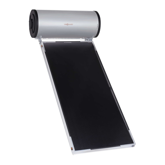
Vitosol 111-F
Type TS1
Thermosiphon solar thermal system with 150, 200 l DHW cylinder and 1 flat-plate
collector
Thermosiphon solar thermal system with 300 l DHW cylinder and 2 flat-plate
collectors
For applicability, see the last page
VITOSOL 111-F
Please keep safe.
5786 170 GB
7/2016
Advertisement
Table of Contents

Related Manuals for Viessmann Vitosol 111-F


Summary of Contents for Viessmann Vitosol 111-F
- Page 1 VIESMANN Service instructions for contractors Vitosol 111-F Type TS1 Thermosiphon solar thermal system with 150, 200 l DHW cylinder and 1 flat-plate collector Thermosiphon solar thermal system with 300 l DHW cylinder and 2 flat-plate collectors For applicability, see the last page VITOSOL 111-F Please keep safe.
- Page 2 These instructions are exclusively intended for author- For replacements, use only original spare parts ised contractors. supplied or approved by Viessmann. Work on electrical equipment must only be carried ■ out by a qualified electrician. ■...
-
Page 3: Table Of Contents
Index Index Information Symbols ....................Intended use ..................Product information ................Commissioning, inspec- Steps - commissioning, inspection and maintenance ......tion, maintenance Parts lists Ordering parts ..................13 Parts list for 150/200 l cylinder ............... 14 Parts list for 300 l cylinder ..............16 Commissioning/service ........................ -
Page 4: Information Symbols
Information Symbols The steps in connection with commissioning, inspec- Symbol Meaning tion and maintenance are found in the "Commission- Reference to other document containing ing, inspection and maintenance" section and identified further information as follows: Step in a diagram: Symbol Meaning The numbers correspond to the order in Steps required during commissioning... -
Page 5: Product Information
Information Product information The thermosiphon solar thermal system consists of a The Vitosol 111-T can be installed on flat roofs and flat-plate collector with highly selective coating and an pitched roofs. enamelled DHW cylinder for DHW heating. A magne- The fixing systems for flat roof installation are available sium anode and an immersion heater are fitted in the for installation angles 15°, 30°... - Page 6 Information Product information (cont.) Fig. 2 Flat-plate collector DHW cylinder Solar return Solar flow...
- Page 7 Information Product information (cont.) Fig. 3 Safety valve, 3 bar (0.3 MPa) and air vent valve DHW connection and pressure/temperature safety valve, 10 bar (1 MPa)/90 °C (T&P valve) Cold water connection, potable water Solar return...
-
Page 8: Commissioning, Inspec-Steps - Commissioning, Inspection And Maintenance
Commissioning, inspection, maintenance Steps - commissioning, inspection and maintenance Commissioning steps Inspection steps Maintenance steps Page • 1. Checks..........................• 2. Filling the DHW cylinder on the DHW side..............• • 3. Filling the DHW cylinder on the solar side..............•... - Page 9 Commissioning, inspection, maintenance Checks Has the safety valve (T&P valve) been installed? Has the hot water drain been installed so that any ■ ■ ■ Has the hot water drain been installed so that any discharged hot water or steam cannot damage the discharged hot water or steam cannot present a risk system and materials in or on the building? to individuals?
- Page 10 Commissioning, inspection, maintenance Checking the safety valve function Cleaning the inside of the DHW cylinder Fig. 5 Immersion heater Magnesium anode 1. Drain the DHW cylinder on the DHW side. 5. Use a chemical cleaning agent to remove hard deposits that cannot be removed with a high pres- 2.
- Page 11 Commissioning, inspection, maintenance Returning the DHW cylinder to use 1. Connect the DHW cylinder to the pipework. 3. Fill the DHW cylinder on the DHW side. Retighten the screws with a maximum torque of 25 Nm. 2. Close the DHW cylinder. Checking connections on the water side for tightness Checking the thermal insulation of the cold water and DHW pipes...
- Page 12 Commissioning, inspection, maintenance Checking the thermal insulation of the cold water and DHW pipes...
-
Page 13: Parts Lists Ordering Parts
Parts lists Ordering parts The following details are required when ordering parts: ■ Serial no. (see type plate) ■ Position number of the part (from this parts list) -
Page 14: Parts List For 150/200 L Cylinder
Parts lists Parts list for 150/200 l cylinder 0001 0002 0003 0004 0008 0005 0006 0007 0010 0011 0012 0009 0015 0016 0013 0014 0019 0020 0017 0018 0021 Fig. 6... - Page 15 Parts lists Parts list for 150/200 l cylinder (cont.) Pos. Part 0001 Elbow 90° 0002 0003 Connection pipe with O-ring 0004 Plug with O-ring 0005 O-rings 0006 Profile clip 0007 Air vent valve 0008 O-rings and guide rings 0009 Safety valve 0010 Immersion heater gasket 0011...
-
Page 16: Parts List For 300 L Cylinder
Parts lists Parts list for 300 l cylinder 0001 0002 0003 0004 0005 0006 0007 0008 0009 0010 0011 0012 0013 0014 0015 0016 0017 0018 0019 0020 0021 0023 0022 0024 0025 Fig. 7... - Page 17 Parts lists Parts list for 300 l cylinder (cont.) Pos. Part 0001 Elbow 90° 0002 0003 Connection pipe with O-ring 0004 Plug with O-ring 0005 O-rings (4 pce) 17.2 x 3 mm 0006 Profile clip 0007 Air vent valve 0008 O-rings (4 pce) 16 x 3 mm 0009 Safety valve...
-
Page 18: Commissioning/Service
Commissioning/service reports Commissioning/service reports Commissioning Maintenance/service Maintenance/service Date: Maintenance/service Maintenance/service Maintenance/service Date: Maintenance/service Maintenance/service Maintenance/service Date: Maintenance/service Maintenance/service Maintenance/service Date: Maintenance/service Maintenance/service Maintenance/service Date:... -
Page 19: Specification
Specification Specification System size 150 l, 2 m 200 l, 2.3 m 300 l, 4 m DIN registration no. Applied for Cylinder capacity Operating pressure on the DHW side Drawable water volume on a sunny day (insolation of 6.7 kWh/m ) with no reheating Draw-off temperature 40 °C (V40) - Page 20 Specification Specification (cont.) Fig. 8 Fig. 9 Fig. 10 Fig. 11...
-
Page 21: Shutdown Final Decommissioning And Disposal
Shutdown Final decommissioning and disposal Viessmann products can be recycled. Components and substances from the system are not part of ordi- nary household waste. For decommissioning the system, isolate the system from the power supply and allow components to cool down where appropriate. -
Page 22: Certificates Declaration Of Conformity
Certificates Declaration of conformity Vitosol 111-F We, Viessmann Werke GmbH & Co. KG, D-35107 Allendorf, declare as sole responsible body that the named product complies with the provisions of the following directives and regulations: 2014/35/EU Low Voltage Directive 2014/30/EU EMC Directive... - Page 24 Serial No.: 7554850 7554851 7554852 7570873 7570874 7571779 7637804 7637808 Viessmann Werke GmbH & Co. KG Viessmann Limited D-35107 Allendorf Hortonwood 30, Telford Telephone: +49 6452 70-0 Shropshire, TF1 7YP, GB Fax: +49 6452 70-2780 Telephone: +44 1952 675000 www.viessmann.com Fax: +44 1952 675040 E-mail: info-uk@viessmann.com...
Need help?
Do you have a question about the Vitosol 111-F and is the answer not in the manual?
Questions and answers