Advertisement
Quick Links
Visit www.clevelandrange.com to locate a
service or sales representative in your area.
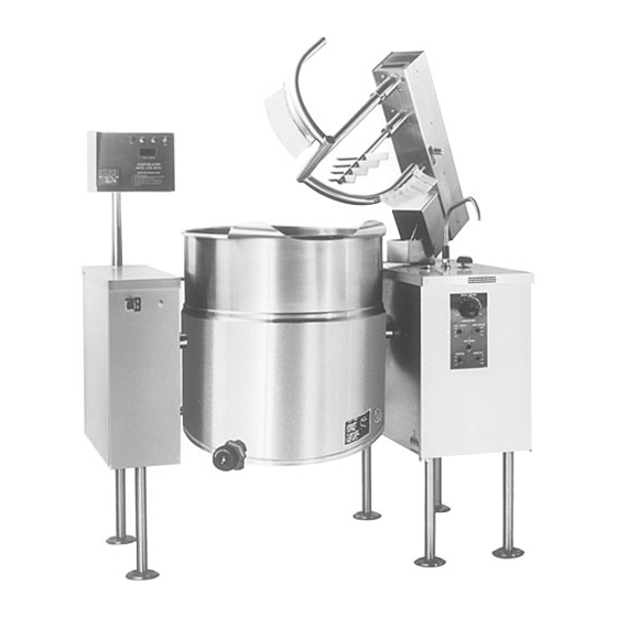
Electric Vertical
Mixer Kettles
Installation, Operation, Maintenance, Parts & Service
This manual is updated as new information and models are released. Visit our website for the latest manual.
MODELS:
MKEL-40-T
MKEL-60-T
MKEL-80-T
MKEL-100-T
TMKEL-40-T
TMKEL-60-T
TMKEL-80-T
TMKEL-100-T
Read the manual thoroughly.
!
Improper installation, operation or
maintenance can cause property
damage, injury or death.
TABLE OF CONTENTS
Statement of Responsibilities . . . . . . . . . . . . . . . . . . . . . . . . . . . . . . . . . . . . . 1
For your safety . . . . . . . . . . . . . . . . . . . . . . . . . . . . . . . . . . . . . . . . . . . . . . . . . . . . 2
Installation . . . . . . . . . . . . . . . . . . . . . . . . . . . . . . . . . . . . . . . . . . . . . . . . . . . . . . . 4
Operating Instructions . . . . . . . . . . . . . . . . . . . . . . . . . . . . . . . . . . . . . . . . . . . . 7
Cleaning Instructions . . . . . . . . . . . . . . . . . . . . . . . . . . . . . . . . . . . . . . . . . . . . 10
Preventative Maintenance . . . . . . . . . . . . . . . . . . . . . . . . . . . . . . . . . . . . . . . 11
Trouble Shooting & Maintenance . . . . . . . . . . . . . . . . . . . . . . . . . . . . . . . . 12
Service Parts . . . . . . . . . . . . . . . . . . . . . . . . . . . . . . . . . . . . . . . . . . . . . . . . . . . . . 25
Part # - KE004011-2 B August 2019
For your future reference.
Model # ______________________________________
Serial # ___________ ____________________________
Model # &
Serial #.
Advertisement

Related Manuals for Welbilt Cleveland MKEL-40-T


Summary of Contents for Welbilt Cleveland MKEL-40-T
-
Page 1: Table Of Contents
Visit www.clevelandrange.com to locate a service or sales representative in your area. Electric Vertical Mixer Kettles Installation, Operation, Maintenance, Parts & Service This manual is updated as new information and models are released. Visit our website for the latest manual. MODELS: For your future reference. -
Page 2: Statement Of Responsibilities
STATEMENT OF RESPONSIBILITIES / DÉCLARATION DES RESPONSABILITÉS / DECLARACIÓN DE RESPONSABILIDADES This document is for use by experienced Ce document est destiné à l’usage des Este documento está destinado para el uso and trained Qualified Cleveland Range, Représentants de Service qualifiés et de los Representantes de Servicio LLC Authorized Service Representatives autorisés de Cleveland Range, LLC qui... -
Page 3: For Your Safety
FOR YOUR SAFETY / POUR VOTRE SÉCURITÉ / PARA SU SEGURIDAD FOR YOUR SAFETY POUR VOTRE SÉCURITÉ PARA SU SEGURIDAD Do not store or use Ne pas entreposer ou No guarde ni use gasolina gasoline or any other utiliser d'essence ou o cualesquiera otros flammable liquids and d'autres liquides ou... - Page 4 WARNING / AVERTISSEMENT / ADVERTENCIA Improper installation, operation, adjustment, alteration, Heavy / Lourd / Pesado service or maintenance can cause property damage, Team or mechanical lift. / Équipe ou remontée injury or death. Read the installation and operating mécanique. / Equipo o elevador mecánico. instructions thoroughly before installing, operating or servicing this equipment.
-
Page 5: Installation
INSTALLATION UNCRATING GENERAL Caution: Environment: Straps under tension and will Operating Criteria Acceptable Range snap when cut. Ambient Air Temperature 15-40 degrees Celsius Relative Humidity 0-80% Carton may contain staples and Altitude 0-3000 meters skid contains nails. Voltage 208-480, 3ph Location Inside building, under ventiltation hood Use proper safety equipment... - Page 6 Postitioning Note: Instructions reflect a more complicated twin Shim as mixer kettle - process for required single mixer kettles is the to make same. level with center console (front and back) Jack 4"x4" or larger (front and back) Skid Fork Lift Tongs Flanged Feed MOVING UNIT While still on skid, move unit as close to final installation...
- Page 7 ELECTRICAL INSTALLATION CHECKS ENSURE THE ELECTRICAL SUPPLY MATCHES THE Although the kettle has been thoroughly tested before leaving KETTLE'S REQUIREMENTS AS STATED ON THE RATING the factory, the installer is responsible for ensuring the proper LABEL. operation of kettle once installed. 1.
-
Page 8: Operating Instructions
OPERATING INSTRUCTIONS WARNING If for any reason this unit is not functioning correctly DO NOT OPERATE. Contact your authorized service agent. OPERATING CONTROLS AND INDICATORS ITEM # DESCRIPTION FUNCTION MAIN POWER SWITCH Power switch for unit. MIX/LIFT SWITCH Sets hydraulics to mix or lift mode. UP/DOWN SWITCH When unit is in lift mode, mixer bridge can be raised or lowered with this switch. - Page 9 OPERATING WARNING: THE KETTLE This unit has been fitted with a warning buzzer for bridge movement and a cover Intended Use: and screen to prevent contact with moving mixer arms. Do not remove or Processing of food and pharmaceuticals in non-residential bypass these safeties.
- Page 10 General Operation Turn MAIN POWER SWITCH on. Turn Steam Control Valve to control heat kettle. Lifting & Lowering Bridge WARNING: Insure FAUCET SPOUT is out of way before raising or lowering bridge. Turn MIX/LIFT SWITCH to lift icon "A". Turn MIXER SPEED CONTROL to "0" and back up to "5".
-
Page 11: Cleaning Instructions
CLEANING INSTRUCTIONS CLEANING INSTRUCTIONS Turn unit off. Remove drain screen (if applicable). Thoroughly wash and rinse the screen either in a sink or a dishwasher. Prepare a warm water and mild detergent solution in the unit. CARE AND CLEANING Remove food soil using a nylon brush. Loosen food which is stuck by allowing it to soak at a low temperature setting. -
Page 12: Preventative Maintenance
PREVENTATIVE MAINTENANCE FOR MAINTENANCE AND REPAIRS CONTACT YOUR AUTHORIZED MANITOWOC SERVICE AGENCY AND HAVE A QUALIFIED SERVICE TECHNICIAN MAINTAIN YOUR EQUIPMENT. WARNING: If for any reason this unit is not functioning correctly DO NOT OPERATE. Contact your authorized service agent. DAILY PRE-STARTUP INSPECTION... -
Page 13: Trouble Shooting & Maintenance
TROUBLESHOOTING AND MAINTENANCE PROCEDURES The following trouble shooting guide and maintenance procedures are meant to be used by Qualified Service Technician ANY REPAIRS TO THE PRESSURE VESSEL MUST BE DONE BY A CERTIFIED PRESSURE VESSEL REPAIR SHOP AND ALL REPAIR METHODS AND MATERIALS MUST BE APPROVED BY THE MANUFACTURER. - Page 14 Measure continuity of ON/OFF switch. Is it operating properly? Go to step #10. Replace defective ON/OFF switch. Unplug control box and measure the resistance across potentiometer. Is it approximately 0 ohms at maximum setting and 50,000 ohms at minimum? Go to step #11. Replace defective potentiometer.
- Page 15 Unplug the control box and measure the resistance across the potentiometer, Is the resistance approximately 0 ohms at maximum and 50,000 ohms at minimum setting? Go to step #3. Replace defective thermistor. Remove kettle thermistor and allow to cool Remove edge connector from control box. Test resistance across edge connector’s pins #2 and #7.
- Page 16 C/ CONTACTOR TEST 1. Remove power to unit. 2. Remove nut holding component mounting plate to console. 3. Pull plate out and place on top of console. (Depending on how the installer wired the kettle you may have to remove the supply wire and reconnect).
- Page 17 F/ SAFETY VALVE Installation Check: Physical Checks 1. Check that the PSI rating ✘ ✔ on the valve matches MAWP (maximum ✔ Tube diameter 4" allowable working ✘ reduced maximum pressure) on the plate Correct Plug length welded to the kettle. Installation 2.
- Page 18 REPAIRING LEAKS IN STEAM JACKETED KETTLE FITTINGS Water Level Probe Pressure Gauge Remove wire from ground lug. Pressure Relief Valve Remove thermistor from tube. If unit will not hold a vacuum the most likely cause is a leak at one of the fittings. Often, the easiest way to eliminate a leak is reseal the suspect areas.
- Page 19 KETTLE JACKET CLEANOUT AND PASSIVATION PROCEDURES The following procedure should be preformed at least once every three years to prevent possible corrosion and ensure the optimum life of the kettle. DANGER: WARNING: Rust inhibitor can be Improper refilling of kettle dangerous.
- Page 20 SSK SOLID STATE CONTROL LUBRICATION PROCEDURE TEST INSTRUCTIONS Lubricate the following parts every three months to insure smooth operation and reduce wear. SSK Solid State Control (part number KE00458-1) TRUNNION HOUSING, Adjusting WORM SCREW AND SWITCH - Push for 5 seconds to enter TEST #1 Screw Press again for TEST #2 and again for TEST #3 TILT GEAR...
- Page 21 RESERVOIR FILL PROCEDURES SPRING WATER REQUIREMENTS The kettle's water level must be maintained at the proper level to submerge the heater When Red “Low Water When the Reservoir is Kettle Light” comes on, Completely Empty, elements. Under normal operating conditions, the sealed water reservoir should never Capacity add Distilled Water Add Distilled Water...
- Page 22 RE-INSTALLING SPEED LUBRICATION CONTROL CABLE Lubricate the following parts every three months to insure smooth operation and reduce wear. MIXER BRIDGE HOUSING There are two grease nipples Front Back on the mixer bridge swivel Cover Cover housing which are accessed by removing the front and Grease back covers on the 18"...
- Page 23 WIRING DIAGRAM SINGLE KETTLES (consult factory for other wiring configurations)
- Page 24 WIRING DIAGRAM TWIN KETTLES (consult factory for other wiring configurations)
- Page 25 FLOW PATH FOR HYDRAULIC SYSTEM Primary Secondary Hydraulic Motor Hydraulic Motor Lift Flow C (Blocking Valve) Control Valve 2 Way Solenoid Valve Raise Lower bridge bridge B (Mix/Lift) 3 Way Fuse (velocity) Solenoid Valve D (Up/Down) 2 Way Solenoid Valve Lift Hydraulic Cylinder...
-
Page 26: Service Parts
SERVICE PARTS WARRANTY Our Company supports a worldwide network of Maintenance and Repair Centers. Contact your nearest Maintenance and Repair Centre for replacement parts, service, or information regarding the proper maintenance and repair of your cooking equipment In order to preserve the various agency safety certification (UL, NSF, ASME/Ntl. Bd., etc.), only factory-supplied replacement parts should be used. - Page 27 HYDRAULIC COMPONENTS (page 2 of 2) ITEM NO. PART NO. DESCRIPTION QTY. KE51607 Flow Control Valve ............2 KE51848 Jack .
- Page 28 PUMP AND MOTOR ASSEMBLY SECTION A-A SECTION B-B VIEW FROM D ITEM PART NUMBER DESCRIPTION KE51889 FILTER & TANK BRETHER KE00860 SPEED CONTROL CABLE & BRACKET ASS"Y FA20030 HEX NUT 3/8-16 FA10747 HEX. HEAD BOLT 3/8-16 X 4'' LG. KE603833 BRACKET KE52050 CABLE CLAMP ARENS #MT304-3...
- Page 29 HYDRAULIC FLOW CONTROL HARNESS PUMP TANK KE01700 PRESS RELIEF VALVE ASSEMBLY 1 (per kettle) KE52382 PRESSURE GAUGE; LIQUID FILL KE51874 PRESSURE RELIEF VALVE FI05054 MALE BRANCH TEE FITTING FI05069 STREET TEE FI05034 STRAIGHT THREAD ADAPTER FI05030-1 ELBOW; 3/8-1 1/4 - 90 DEG. KE00713I &...
- Page 30 TEMPERATURE CHART RECORDER BOX ASSEMBLY MKDL-T / TMKDL-T / MKGL-T / HA-MKGL SECTION A-A CONTROLLER WATER METER KE003730A * NOTE: PARTS NOT SHOWN ON DWG. KE003209-B...
- Page 31 ELECTRICAL COMPONENT ASSEMBLY DIAGRAM ILLUSTRATES CONTROL PANEL OF TWIN KETTLE WITH ALL OPTIONS. INDIVIDUAL CONTROL PANELS MAY VARY. NOTE: ITEMS #40 TO #43 AND #45 ARE NOT SHOWN KE00888-1 MKDL & MKEL COMMON PARTS KE00888R DESCRIPTION DESCRIPTION KE52936-6 FUSE- 3 AMP KE50343-7 COMPONENT MOUNTING PLATE KE95242-2...
- Page 32 REMOTE CONTROL ASSEMBLY For units with Water Meter and/or DTCI option e l a ITEM NO. PART NO. DESCRIPTION QTY. KE53479-1 Digital Temperature Controller and Indicator ......1 KE53257 Digital Counter .
- Page 33 ELECTRIC KETTLE COMPONENT PLATE ITEM NO. PART NO. DESCRIPTION QTY. KE50343-29 COMPONENT PLATE, 25 gallon ..........1 KE50343-9 COMPONENT PLATE, 30 gallon and up .
- Page 34 MAIN CONSOLE CONTROLS For standard Mixer Kettles INCLUDED WITH ALL SWITCHES. ITEM NO. PART NO. DESCRIPTION QTY. KE52190 Knob, Speed Control ..........1 KE00860 Cable and Bracket, Speed Control (includes Micro Switch, item 9) .
- Page 35 WATER METER ASSEMBLY - 18" CONSOLE ITEM NO. PART NO. DESCRIPTION QTY. FI05058 3/4" Cross ............1 KE02055-2 Steam Valve Modification .
- Page 36 MANUAL & POWER TILT, ELECTRIC AND DIRECT STEAM - 10" CONSOLE 31 32 40 41 DETAIL 21 3 (MKEL & MKDL) MKEL 31 32 40 41 FOOT DETAIL (MKEL & MKDL) 21 3 MKDL ITEM PART # DESCRIPTION ITEM PART # DESCRIPTION HANDWHEEL ASS'Y.;...
- Page 37 COMPONENT PLATE ASSEMBLY - POWER TILT KETTLES SEE ABOVE KE02185-C...
- Page 38 TANGENT DRAW-OFF VALVES 1.5” & 3” TANGENT DRAW-OFF VALVE ITEM NO. PART NO. DESCRIPTION QTY. 1. - 7. KE50219 1.5” DRAW-OFF ASSEMBLY ........1 KE50973 3”...
- Page 39 BUTTERFLY VALVE, 3” ITEM NO. PART NO. DESCRIPTION QTY. 1. - 7. KE52286 Butterfly Valve (includes housing) ........1 FA11224 Bolt, 5/16-18 x1"...
- Page 40 AIR VALVE ASSEMBLY FOR FPVA-3 KE02291-1 AIR SOLENOID ASSEMBLY FOR FPVA-3 KE02340-C CONSULT FACTORY CONSULT FACTORY SPARE PARTS LIST PART NO. DESCRIPTION ............QTY. KE51834 SCRAPER BLADES .
- Page 42 To learn how Welbilt Foodservice and its leading brands can equip you, visit our global web site at www.welbilt.com, then discover the regional or local resources available to you. ©2016 Welbilt Foodservice except where explicitly stated otherwise. All rights reserved. Con nuing product improvement may necessitate change of specifia ons without no ce.
Need help?
Do you have a question about the Cleveland MKEL-40-T and is the answer not in the manual?
Questions and answers