Table of Contents
Advertisement
Quick Links
Visit www.clevelandrange.com to locate a
service or sales representative in your area.
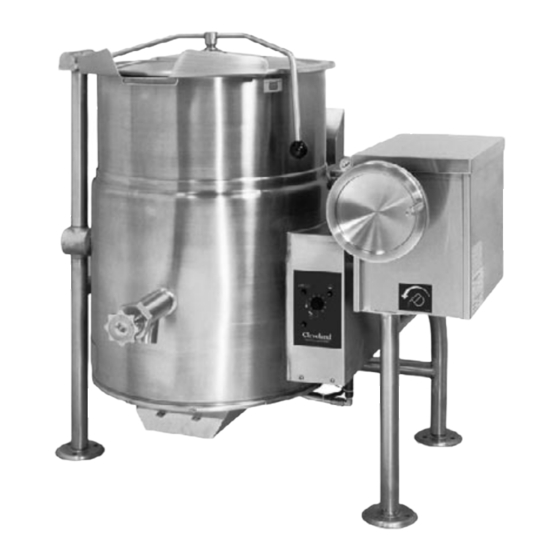
Gas 25 Gallon Kettle
Installation, Operation, Maintenance, Parts & Service
This manual is updated as new information and models are released. Visit our website for the latest manual.
MODELS:
KGL-25
KGL-25-T
Read the manual thoroughly.
!
Improper installation, operation or
maintenance can cause property
damage, injury or death.
TABLE OF CONTENTS
Statement of Responsibilities . . . . . . . . . . . . . . . . . . . . . . . . . . . . . . . . . . . . . 1
For your safety . . . . . . . . . . . . . . . . . . . . . . . . . . . . . . . . . . . . . . . . . . . . . . . . . . . . 2
Installation . . . . . . . . . . . . . . . . . . . . . . . . . . . . . . . . . . . . . . . . . . . . . . . . . . . . . . . 4
Operating Instructions . . . . . . . . . . . . . . . . . . . . . . . . . . . . . . . . . . . . . . . . . . . . 6
Cleaning Instructions . . . . . . . . . . . . . . . . . . . . . . . . . . . . . . . . . . . . . . . . . . . . . 7
Preventative Maintenance . . . . . . . . . . . . . . . . . . . . . . . . . . . . . . . . . . . . . . . . 8
Safety Inspection Checklist . . . . . . . . . . . . . . . . . . . . . . . . . . . . . . . . . . . . . . . . 9
Operating Sequences . . . . . . . . . . . . . . . . . . . . . . . . . . . . . . . . . . . . . . . . . . . . 11
Troubleshooting Guide . . . . . . . . . . . . . . . . . . . . . . . . . . . . . . . . . . . . . . . . . . .12
Service Procedures . . . . . . . . . . . . . . . . . . . . . . . . . . . . . . . . . . . . . . . . . . . . . . .16
Service Parts . . . . . . . . . . . . . . . . . . . . . . . . . . . . . . . . . . . . . . . . . . . . . . . . . . . . . 21
Part # - KE004021-2 B August 2019
KGT-25-T
For your future reference.
Model # ______________________________________
Serial # ___________ ____________________________
KGT-25
Model # &
Serial #.
Advertisement
Table of Contents

Related Manuals for Welbilt KGL-25


Summary of Contents for Welbilt KGL-25
-
Page 1: Table Of Contents
Installation, Operation, Maintenance, Parts & Service This manual is updated as new information and models are released. Visit our website for the latest manual. MODELS: For your future reference. KGL-25 Model # ______________________________________ KGL-25-T Serial # ___________ ____________________________ Model # &... -
Page 2: Statement Of Responsibilities
STATEMENT OF RESPONSIBILITIES / DÉCLARATION DES RESPONSABILITÉS / DECLARACIÓN DE RESPONSABILIDADES This document is for use by experienced Ce document est destiné à l’usage des Este documento está destinado para el uso de and trained Qualified Cleveland Range, Représentants de Service qualifiés et los Representantes de Servicio calificados y LLC Authorized Service Representatives autorisés de Cleveland Range, LLC qui... -
Page 3: For Your Safety
FOR YOUR SAFETY / POUR VOTRE SÉCURITÉ / PARA SU SEGURIDAD FOR YOUR SAFETY POUR VOTRE SÉCURITÉ PARA SU SEGURIDAD Do not store or use Ne pas entreposer ou No guarde ni use gasolina gasoline or any other utiliser d'essence ou o cualesquiera otros flammable liquids and d'autres liquides ou... - Page 4 WARNING / AVERTISSEMENT / ADVERTENCIA Improper installation, operation, adjustment, alteration, Heavy / Lourd / Pesado service or maintenance can cause property damage, Team or mechanical lift. / Équipe ou remontée injury or death. Read the installation and operating mécanique. / Equipo o elevador mecánico. instructions thoroughly before installing, operating or servicing this equipment.
-
Page 5: Installation
U.S.A. National Fire Protection Associations NFPA96 regulations. These standards Unit with Model # Unit shipping have also been adopted by the National Building Code in Canada. KGL-25 320 lbs. 360 lbs. KGL-25-T 320 lbs. 360 lbs. POSITIONING UNCRATING This unit must be installed in accordance with the clearances shown on the rating label which is adhered to the unit. - Page 6 2. Feed permanent copper wiring through the cut-out in the rear or bottom of the console, and fasten to the terminal ENSURE THE GAS SUPPLY MATCHES THE KETTLE'S block. Be sure to connect the ground wire to the separate REQUIREMENTS AS STATED ON THE RATING PLATE. ground terminal connector (ground lug).
-
Page 7: Operating Instructions
WARNING OPERATING INSTRUCTIONS If for any reason this unit is not functioning correctly DO NOT OPERATE. Contact your authorized service agent. OPERATING THE KETTLE Perform daily startup inspection. Temperature Approximate Control Product Temperature Setting ° F ° C OPERATING CONTROLS AND INDICATORS NOTE: Certain combinations of ingredients will result in temperature variations... -
Page 8: Cleaning Instructions
CLEANING INSTRUCTIONS CLEANING INSTRUCTIONS Turn unit off. Remove drain screen (if applicable). Thoroughly wash and rinse the screen either in a sink or a dishwasher. Prepare a warm water and mild detergent solution in the unit. CARE AND CLEANING Remove food soil using a nylon brush. Cooking equipment must be cleaned Loosen food which is stuck by allowing it to soak at a low temperature setting. -
Page 9: Preventative Maintenance
PREVENTATIVE MAINTENANCE FOR MAINTENANCE AND REPAIRS CONTACT YOUR AUTHORIZED MANITOWOC SERVICE AGENCY AND HAVE A QUALIFIED SERVICE TECHNICIAN MAINTAIN YOUR EQUIPMENT. WARNING: If for any reason this unit is not functioning correctly DO NOT OPERATE. Contact your authorized service agent. DAILY PRE-STARTUP INSPECTION... -
Page 10: Safety Inspection Checklist
SAFETY INSPECTION CHECKLIST NOTE: The following instructions are intended for use by qualified service personnel. The following steps should be completed IN SEQUENCE. A/ KETTLE PREPARATION 1. Disconnect main power at fused disconnect switch. 2. Kettle should be cold. If necessary add water to kettle pot to cool unit. 3. - Page 11 E/ SAFETY THERMOSTAT Installation Check Correct Incorrect Installations Installation ✔ Safety thermostat probe is not completely inserted into tubing (except KET-3-T that Probe has a small loop). fully Safety thermostat probe inserted is removed from tubing. in tube ✘ ✘ ✘...
-
Page 12: Operating Sequences
G/ CALIBRATING PROCEDURE 260º - 265º 1. Kettle must be empty when this procedure is executed. 265º MAXIMUM ✔ 2. Insure the unit has a vacuum before you begin calibrating procedures. If unit KETTLE TEMPERATURE requires venting see REFERENCE SECTION (KETTLE VENTING INSTRUCTIONS). -
Page 13: Troubleshooting Guide
TROUBLESHOOTING GUIDE PROBLEM: KGL-25 Does red light Replace the Does red light go Add water to come on when unit wire harness in off shortly after Kettle Won't jacket of Kettle. is first turned on? the trunion unit is turned on? - Page 14 PROBLEM: KGL-25 Kettle Not Does the kettle See Problem: heat at all? kettle won't heat. Hot Enough With kettle pot empty and temperature knob Unit is set at 10, is the operating temperature of the properly surface of the pot...
- Page 15 PROBLEM: With the kettle empty and the KGL-25 temperature set at Kettle Gets kettle is working 10, is the surface properly. temp 260-265 Too Hot degrees? Does the kettle Is the resistance of continue to call for ;the thermister heat (green light...
-
Page 16: Service Procedures
SERVICE PROCEDURES FOR MAINTENANCE AND REPAIRS CONTACT YOUR AUTHORIZED MANITOWOC SERVICE AGENCY AND HAVE A QUALIFIED SERVICE TECHNICIAN MAINTAIN YOUR EQUIPMENT. KETTLE VENTING INSTRUCTIONS 3. Turn kettle OFF. Add cold water to kettle until its surface temperature is below 100°F. The pressure gauge needle should be in the green zone, Pressure... - Page 17 CALIBRATING PROCEDURE RESERVOIR FILL PROCEDURES Insure the unit has a vacuum before you begin calibrating procedures. If unit requires venting refer to Kettle Venting Instructions. Turn dial to "10" (Max.). Allow the unit to cycle twice. Check temperature of the inner kettle surface with a digital surface thermometer.
- Page 18 KETTLE JACKET CLEANOUT AND PASSIVATION PROCEDURES The following procedure should be preformed at least once every three years to prevent possible corrosion and ensure the optimum life of the kettle. Remove Attach Fill unit via Street Elbow Pressure Street Relief Elbow Valve Important-...
- Page 19 Atmospheric Burner Gas Kettles BTU's per Water # of INSTRUCTIONS - Hour Type Column Orifices KGL-25, KGL-25-T 90000 Natural Gas to Propane Gas 90000 TO MAIN GAS SUPPLY CAUTION The gas supply shall be shut off prior to disconnecting PIPE...
- Page 20 REPAIRING LEAKS IN STEAM JACKETED KETTLE FITTINGS Water Level Probe Pressure Gauge Pressure Relief Valve Remove wire from ground lug. Remove thermistor from tube. If unit will not hold a vacuum the most likely cause is a leak at one of the fittings. Often, the easiest way to eliminate a leak is reseal the suspect areas.
- Page 21 SSK SOLID LUBRICATION PROCEDURE SSK Solid State Control (part number KE00458-1) STATE SWITCH - Push for 5 seconds to enter TEST #1 Lubricate the following parts every three months to insure Press again for TEST #2 and again for TEST #3 CPU - Rapid flashing during normal operation TEST #1 = 1 flash/sec Water level test...
-
Page 22: Service Parts
SERVICE PARTS WARRANTY Our Company supports a worldwide network of Maintenance and Repair Centers. Contact your nearest Maintenance and Repair Centre for replacement parts, service, or information regarding the proper maintenance and repair of your cooking equipment In order to preserve the various agency safety certification (UL, NSF, ASME/Ntl. Bd., etc.), only factory- supplied replacement parts should be used. - Page 23 COMPONENT MOUNTING PLATES TILTING MODELS STATIONARY MODELS 3 5 10 2 6 9 ITEM NO. PART NO. DESCRIPTION QTY. KE01927-1 COMPONENT MOUNTING PLATE (STATIONARY MODELS) ....1 KE01927 COMPONENT MOUNTING PLATE (TILTING MODELS) .
- Page 24 BURNER ASSEMBLY 4 5 6 ITEM NO. PART NO. DESCRIPTION QTY. KE54897-1 MANIFOLD ........... . .1 KE54890-1 IGNITION GUARD .
- Page 25 TANGENT DRAW-OFF VALVE ITEM NO. PART NO. DESCRIPTION QTY. 1. - 7. KE50973 2” DRAW-OFF ASSEMBLY .........1 KE50972-B 3”...
- Page 26 GENERAL ASSEMBLY - STATIONARY MODELS (pg. 1 of 2) VIEW "B" 7 8 10 MANIFOLD & BURNER TUBE PIPING DETAIL 10 L1 14 15 16 VIEW "A" COMPONENT MOUNTING BOX WITH LID REMOVED 19 20...
- Page 27 GENERAL ASSEMBLY - STATIONARY MODELS (pg. 2 of 2) ITEM NO. PART NO. DESCRIPTION QTY. KE00099 ADJUSTABLE FOOT ..........3 KE01928-2 COMPONENT MOUNTING PLATE ASSEMBLY .
- Page 28 SUPPLY CORD ..........1 CHS-KGL-25-T SPRING HINGE COVER .
- Page 29 GENERAL ASSEMBLY - TILTING MODELS (pg. 2 of 3) 39 40 41 36 42 43 45 43 42 47 48 49 50 52 53 54 FI05134-1 COMPRESSION FITTING ......... .2 FI05198-5 COMPRESSION ELBOW .
- Page 30 GENERAL ASSEMBLY - TILTING MODELS (pg. 3 of 3) FI00040 ELBOW ............1 FA19177 HEX SOCKET SET SCREW .
- Page 31 CONSOLE CONTROLS ITEM NO. PART NO. DESCRIPTION QTY. SE00114 POTENTIOMETER WITH ON/OFF SWITCH, C/W ITEM #2 ....1 KE51005 RUBBER BOOT ..........1 KE50569-1 KNOB, POTENTIOMETER .
- Page 32 HINGE ASSEMBLY ITEM NO. PART NO. DESCRIPTION QTY. Hinge Assembly 1. - 11 KE00597-1 25 - 40 Gallon, 20 Gallon Full Jacketed .......1 KE00597-2 60 - 80 Gallon, 30 - 40 Gallon Full Jacketed .
- Page 34 To learn how Welbilt Foodservice and its leading brands can equip you, visit our global web site at www.welbilt.com, then discover the regional or local resources available to you. ©2016 Welbilt Foodservice except where explicitly stated otherwise. All rights reserved. Con nuing product improvement may necessitate change of specifia ons without no ce.
Need help?
Do you have a question about the KGL-25 and is the answer not in the manual?
Questions and answers