Table of Contents
Advertisement
Quick Links
Advertisement
Table of Contents

Related Manuals for Ironton 46463


Summary of Contents for Ironton 46463
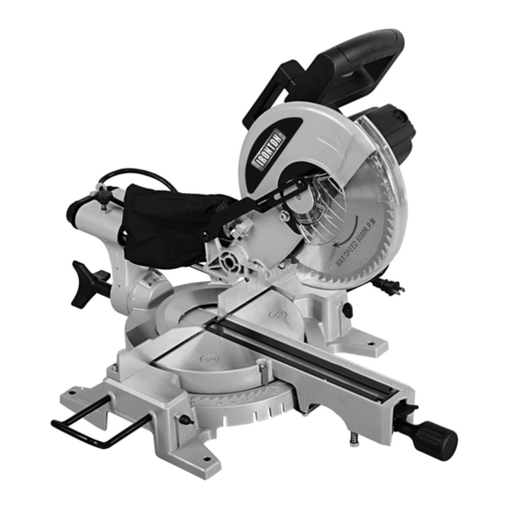
- Page 1 10IN. COMPOUND MITER SAW OWNER’S MANUAL WARNING: Read carefully and understand all ASSEMBLY AND OPERATION INSTRUCTIONS before operating. Failure to follow the safety rules and other basic safety precautions may result in serious personal injury. Item # 46463 1 OF 20...
-
Page 2: Intended Use
For technical questions and replacement parts, please call 1-800-222-5381. INTENDED USE The Ironton Compound Miter Saw’s impressive 2.4 HP, 15 Amp motor gives you the power you need to cut both wood and composite materials without slowing down. TECHNICAL SPECIFICATIONS... -
Page 3: General Safety Rules
GENERAL SAFETY RULES Read and understand all instructions. Failure to follow all instructions listed below WARNING: may result in serious injury. CAUTION: Do not allow persons to operate or assemble this Compound Miter Saw until they have read this manual and have developed a thorough understanding of how the Compound Miter Saw works. -
Page 4: Electrical Safety
Dress properly. Do not wear loose clothing or jewelry. Contain long hair. Keep your hair, clothing, and gloves away from moving parts. Loose clothes, jewelry or long hair can be caught in moving parts. Avoid accidental starting. Be sure the switch is OFF before plugging in the tool. Carrying tools with your finger on the switch or plugging in tools that have the switch ON invites accidents. - Page 5 If you use an extension cord, make sure to use only UL listed cords having the correct gauge and length (see chart A). Chart A: RECOMMENDED MINIMUM WIRE GAUGE FOR EXTENSION CORDS (120 VOLTS) NAME PLATE AMPERES (at full load) 25’...
-
Page 6: Miter Saw Safety Warnings
from the unit. Never reach around saw. Keep hands out of path of saw blade. Never reach in back of the fence. MITER SAW SAFETY WARNINGS For Your Own Safety Read Instruction Manual Before Operating Miter Saw Wear eye protection. Keep hands out of path of saw blade. -
Page 7: Vibration Safety
close proximity to heart pacemaker could cause pacemaker interference or pacemaker failure. VIBRATION SAFETY This tool vibrates during use. Repeated or long-term exposure to vibration may cause temporary or permanent physical injury, particularly to the hands, arms and shoulders. To reduce the risk of vibration-related injury: Anyone using vibrating tools regularly or for an extended period should first be examined by a doctor and then have regular medical check-ups to ensure medical problems are not being... -
Page 8: Work Piece And Work Area Setup
home made saw table. There are bolt holes provided in each of the four legs of the base. These should be firmly mounted using bolts (not included) to your saw stand or saw table (not included). This will help prevent tipping or movement of the saw, preventing injury. Also, the use of a saw table will make it easier to efficiently handle work materials and make more accurate cuts. -
Page 9: Adjusting The Miter Angle
ADJUSTING THE MITER ANGLE A miter cut is one that is at an angle across the horizontal surface of the material. You will commonly make 45º miter cuts to join two pieces in a right angle corner. A 30º cut is often used for a scarf joint or to make a chamfered end. -
Page 10: Making A Cut
the Slide Lock Wing Screw at the back of the saw. To make a bevel cut, release the Bevel Lock Lever; rotate the blade assembly to the desired bevel angle, then lock the blade assembly in place using the Bevel Lock Lever. Making bevel cuts is discussed in more detail later in this manual. -
Page 11: Replacing The Blade
WARNING: TO PREVENT SERIOUS INJURY FROM TOOL FAILURE: Do not use damaged equipment. If abnormal noise or vibration occurs, have the problem corrected before further use. Cleaning, Maintenance, and Lubrication BEFORE EACH USE, inspect the general condition of the tool. Check for loose screws, misalignment or binding of moving parts, cracked or broken parts, damaged electrical wiring, and any other condition that may affect its safe operation. - Page 12 Figure B: Removing Bolt 4. Remove the Safety Screw. (See Figure C.) Figure C: Removing Safety Screw 5. Raise the Blade Guard and Center Cover. (See Figure D.) Figure D: Raise Blade Guard 6. While holding in the Arbor Lock Button, use the Wrench to loosen the Arbor Bolt by turning it clockwise.
-
Page 13: Adjusting The Fence
(See Figure F.) Be sure to match the direction marked on the new blade with the direction marked on the saw Blade Housing. Figure F: Removing Blade 9. Replace the Outer Flange and Arbor Bolt. Tighten the Arbor Bolt securely using the Wrench by turning it counterclockwise. -
Page 14: Adjusting Or Replacing The Kerf Board
ADJUSTING THE BEVEL ANGLE For making accurate cuts, the Saw Blade must be adjusted to be exactly vertical to the Table. To check the angle, have the blade assembly in its normal upright position. Make a cut on a piece of flat sided, fairly thick scrap material. -
Page 15: Troubleshooting
TROUBLESHOOTING Problem Possible Causes Likely Solutions 1. No power at outlet. 1. Check power at outlet. Tool will not start 2. Cord not connected. 2. Check that cord is plugged in. 1. Low power supply or improper extension 1. Check power supply and power cords. Tool operates sporadically cords. - Page 16 DIAGRAM 16 OF 20...
-
Page 17: Parts List
PARTS LIST Name Name Bolt M6x25 Lock Handle Base Bolt M5x14 Extension Arm Bushing Screw Oil Cover Foot Bearing Bolt M8x50 Bolt M5x10 Mount Spring Washer Line Button Flat Washer Washer Plate Bolt M6x10 Rub Slice Limit Plate Knob M6x20 Spring Handle Ball Pin 3x20... - Page 18 Name Name Dust Hood Knob Blade Cover Lock Washer Link Pole Plank Bearing Switch Spring Washer Switch Spring Gear Switch Button Front Cover Handle Up Part Bearing Bolt ST4.2X18 Outer Axis Handle Key 4x13 Bolt ST6.3x25 Bearing Cover Bolt M5x45 Bolt M5x18 Bolt ST4.2X14 Inner Flange...
- Page 19 Northern Tool and Equipment Company, Inc. ("We'' or '"Us'') warrants to the original purchaser only ("You'' or “Your”) that the Ironton Power Tool product purchased will be free from material defects in both materials and workmanship, normal wear and tear excepted, for a period of one year from date of purchase. The foregoing warranty is valid only if the installation and use of the product is strictly in accordance with product instructions.
- Page 20 WARNING Some dust created by power sanding, sawing, grinding, drilling, and other construction activities contains chemicals known to the State of California to cause cancer, birth defects or other reproductive harm. Some examples of these chemicals are: • Lead from lead-based paints, •...
Need help?
Do you have a question about the 46463 and is the answer not in the manual?
Questions and answers