Table of Contents
Advertisement
Quick Links
Advertisement
Table of Contents

Subscribe to Our Youtube Channel
Related Manuals for Ironton 58123


Summary of Contents for Ironton 58123
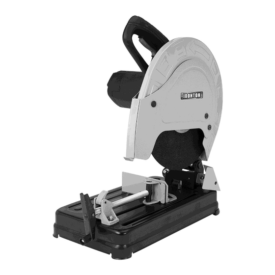
- Page 1 14 Inch Abrasive Chop Saw Owner’s Manual WARNING: Read carefully and understand all ASSEMBLY AND OPERATION INSTRUCTIONS before operating. Failure to follow the safety rules and other basic safety precautions may result in serious personal injury. Item #58123 READ & SAVE THESE INSTRUCTIONS...
- Page 2 ® Thank you very much for choosing an Ironton product! For future reference, please complete the owner’s record below: Serial Number/Lot Date Code: ________________________________ Purchase Date: ____________________________________________ Save the receipt, warranty, and this manual. It is important that you read the entire manual to become familiar with this product before you begin using it.
-
Page 3: Table Of Contents
Table of Contents Intended Use ............................4 Packaging Contents ..........................4 Technical Specifications ........................4 Important Safety Information ....................... 4 Specific Operation Warnings ....................... 6 Grounding .............................. 7 Extension Cords ............................ 8 Main Parts of Saw ..........................9 Assembly Instructions ........................11 Before Each Use .......................... -
Page 4: Intended Use
Intended Use The Ironton 14 Inch Abrasive Chop Saw has the power to easily cut through cast iron piping, angle iron, threaded rods, conduit, square tubing, and more. The saw can cut 4 inches round or 3 1/2 inches square stock at angles up to 45 degrees. - Page 5 ⚠WARNING WORK AREA SAFETY Inspect the work area before each use. Keep work area clean, dry, free of clutter, and well-lit. Cluttered, wet, or dark work areas can result in injury. Using the product in confined work areas may put you dangerously close to cutting tools and rotating parts. ...
-
Page 6: Specific Operation Warnings
Do not force the saw. Products are safer and do a better job when used in the manner for which they are designed. Plan your work, and use the correct product for the job. Check for damaged parts before each use. Carefully check that the product will operate properly and perform its intended function. -
Page 7: Grounding
blade to break. Check for misalignment or binding of moving parts, breakage of parts and any other condition that may affect the power tool’s operation. Grounding ⚠WARNING This machine must be grounded while in use to protect the operator from electrical shock. This unit is equipped with an electrical cord that has an equipment grounding conductor and a grounding plug. -
Page 8: Extension Cords
Extension Cords ⚠WARNING USE A PROPER EXTENSION CORD. Make sure your extension cord is in good condition. When using an extension cord, be sure to use one heavy enough to carry the current your product will draw. An undersized cord will cause a drop in line voltage, resulting in loss of power and cause overheating. -
Page 9: Main Parts Of Saw
Main Parts of Saw Page 9 of 21... - Page 10 Reference Subassembly trigger switch lock-off button screws for shield flake disk guard front spark shield cutting off disc spindle lock rear spark shield base rubber foot Vice lock release lever vice handle vice handle nut vice fence lockdown knob depth stop hex key Page 10 of 21...
-
Page 11: Assembly Instructions
Assembly Instructions ⚠WARNING Always remove the plug from the power source. Replacing a Cut-Off Disc 1. Loosen and remove the screws for shield flake (fig. 1). 2. Hold the spindle lock lever and at the same time, rotate the hex key supplied to remove the disc bolt. -
Page 12: Before Each Use
4. Replace and turn the new disc by hand, ensuring that it rotates fully and does not wobble (fig 4). Tighten the bolt in a clockwise direction. 5. Replace the front spark shield by locating the center pivot section of the spark shield into the raised center section of the upper disc guard (fig 4). - Page 13 Adjusting the Machine Head Push the machine head down, and at the same time, insert the lock down knob (fig 5) into the hole to lower the head, confirming that it’s attached. Similarly, pull the lock down knob out of the hole to raise the machine head upward.
- Page 14 Operating 1. Push the lock-off button and pull the trigger to start the saw. 2. Bring the disc down onto the workpiece and allow it to cut its way through the workpiece without undue force (fig 7). 3. Once the cut is finished, raise the arm to clear the disc from the workpiece, release the trigger and the cut off grinder will stop.
-
Page 15: After Each Use
To change the cutting angle, loosen the 2 hex screws securing the fence using the hex key supplied (fig 8). 1. Move the rear fence to the desired angle using the scale as a guide (fig. 9). 2. Tighten the 2 hex bolts to secure the fence is in position. Attaching the Vice Handle The vice can be adjusted quickly by pulling the vice handle nut. -
Page 16: Maintenance
Store idle power tools out of the reach of children and do not allow persons unfamiliar with the power tool or these instructions to operate the saw. Maintenance ⚠WARNING Keep cutting tools sharp and clean. Properly maintained cutting tools with sharp cutting edges are less likely to bind and are easier to control. -
Page 17: Parts Diagram
Parts Diagram Parts List Reference Part Description Quantity rivet adjusting handle flat washer open pin advancing nut spring support hexagon spring washer adjustable pliers board Page 17 of 21... - Page 18 Reference Part Description Quantity hexagon bolt fixed pliers board hexagon bolt spring washer flat washer hexagon bolt hexagon nut fixation pin cross screw spring washer spring spring washer fixation pin anti-loose nut chain hexagon holt spring hexagon bolt metal base rubber foot anti-dust board connecting rod...
-
Page 19: Replacement Parts
Reference Part Description Quantity fixation washer inductance drawn stator ball bearing rotor ball bearing anti-wind ring cross screw screw cross screw rear cover carbon brush holder carbon brush carbon brush cover cross screw cross screw cross screw switch capacitor plastic support left housing right housing cord plug... -
Page 20: Limited Warranty
Northern Tool and Equipment Company, Inc. ("We'' or ''Us'') warrants to the original purchaser only (''You'' or ''Your'') that the Ironton product purchased will be free from material defects in both materials and workmanship, normal wear and tear excepted, for a period of one year from date of purchase. - Page 21 Distributed by: Northern Tool & Equipment Company, Inc. Burnsville, Minnesota 55306 www.northerntool.com Made in China Page 21 of 21...
Need help?
Do you have a question about the 58123 and is the answer not in the manual?
Questions and answers