Table of Contents
Advertisement
Quick Links
Advertisement
Table of Contents

Subscribe to Our Youtube Channel
Related Manuals for Ironton 45988


Summary of Contents for Ironton 45988
- Page 1 10IN. TABLE SAW OWNER’S MANUAL WARNING: Read carefully and understand all ASSEMBLY AND OPERATION INSTRUCTIONS before operating. Failure to follow the safety rules and other basic safety precautions may result in serious personal injury. Item# 45988...
-
Page 2: Intended Use
For technical questions please call 1-800-222-5381. INTENDED USE The Ironton Table Saw has been designed to cut timber and timber products. The large work table with easy to install side tables provide greater stability when cutting larger workpieces. Designed for multi-purpose applications such as ripping and crosscuts of timber, chipboard and plywood. -
Page 3: General Safety Rules
GENERAL SAFETY RULES WARNING: Read and understand all instructions. Failure to follow all instructions listed below may result in serious injury. CAUTION: Do not allow persons to operate or assemble this Table Saw until they have read this manual and have developed a thorough understanding of how the Table Saw works. - Page 4 3) Personal safety a) Stay alert, watch what you are doing and use common sense when operating a power tool. Do not use a power tool while you are tired or under the influence of drugs, alcohol or medication. A moment of inattention while operating power tools may result in serious personal injury.
- Page 5 TABLE SAW USE AND CARE Do not modify the Table Saw in any way. Unauthorized modification may impair the function • and/or safety and could affect the life of the equipment. There are specific applications for which the Table Saw was designed. Always check of damaged or worn out parts before using the Table Saw.
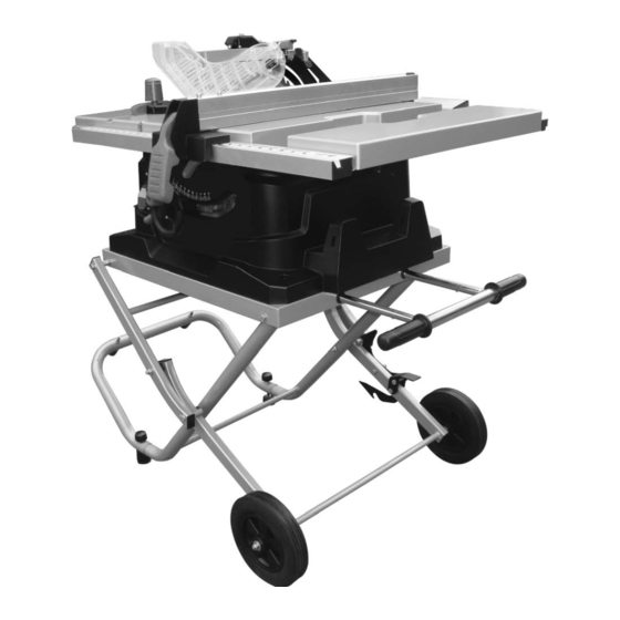
- Page 6 ASSEMBLY Riving knife Table insert Blade guard Miter gauge Working table ON/OFF switch with key Mounting holes Rip fence Right extension table Blade bevel lock knob Blade tilt/elevation handwheel Kickback pawls Rear table Blade wrench Push stick Blade Overload reset switch Stand Wheel Handle...
-
Page 7: Assembly And Adjustments
B. Stand parts WARNING: If any part is missing or damaged, do not plug in the table saw until you have replaced the missing or damaged parts. To avoid injury, the styrofoam block should be removed between the motor and the table. ASSEMBLY AND ADJUSTMENTS WARNING: DO NOT CONNECT THE PLUG TO THE OUTLET UNTIL ALL... - Page 8 ASSEMBLE THE STAND (fig. 1-6) • Unpack all of the parts, and group them by type and size. Refer to the parts list for correct quantities. (See Fig. 1) • Attach the tubes of the stand assembly (B) with the corresponding tubes of the stand assembly (A) and align the holes.
- Page 9 • Slide the flat washer M10 (G), roller sleeves (E), wheels (C), and flat washer M8 (H) and nut M8 (J) onto the axle through the hole in the center of the wheel as illustrated. Secure in place using the wrench. (See Fig. •...
- Page 10 for height. TO OPEN THE LEG STAND (Fig. 9-11) • Grasp the grips on the stand and stand the table saw upright as shown Fig. 9. • Step on the leaser lever and pull the grips toward you at the same time. •...
- Page 11 TO CLOSE THE LEG STAND AND MOVE THE SAW (Fig. 12-15) • Remove any workpieces from the tool. • Remove and securely store any tools or accessories such as rip fence, miter gauge blade guard, push stick, etc. • Lower the saw blade. To close the leg stand: •...
- Page 12 MOUNTING THE TABLE SAW TO A WORKBENCH (FIG.16-17) • Step.1: If the stand will not be used, the table saw must be properly secured to a sturdy workbench using the four mounting holes on the base. • Step.2: The workbench must have a hole that is large enough to allow for sawdust fall through and removal.
- Page 13 TO REMOVE/REPLACE/ALIGN THE TABLE INSERT (Fig. 19) WARNING: The table insert must be level with the saw table. If the table insert is too high or too low, the workpiece can catch on the uneven edges resulting in binding or kickback which could result in serious personal injury.
- Page 14 • Place the jaws of the open-ended wrench (7) on the flats of the flange (5) in order to prevent the arbor from turning while tightening. Tighten the arbor nut by turning it clockwise using the open-ended wrench (7) (See Fig. 23). WARNING: MAKE SURE THE SAW BLADE, ARBOR FLANGE, AND NUT ARE PROPERLY SEATED, AND VERIFY THAT THE ARBOR NUT IS...
- Page 15 TO INSTALL THE ANTI-KICKBACK PAWLS AND BLADE GUARD (FIG.27-30) NOTE: Anti-kickback pawls should only be installed for through cuts. • Unplug the saw. • Raise the saw blade. • Place the riving knife in “up” position. TO INSTALL ANTI-KICKBACK PAWLS: •...
- Page 16 CHECK AND ALIGN THE RIVING KNIFE AND SAW BLADE (FIG.31-32) If the riving knife is out of alignment with the saw blade, adjustment is needed. • Unplug the saw. • Raise the saw blade by turning the height adjusting knob clockwise. •...
- Page 17 • Push the handle down to lock it, and tighten both screws. • If fence is loose when handle is in the lock (down) position, follow these steps: • Lift the handle (2) and turn the adjusting nut (5) clockwise until the rear clamp is snug. Do not turn the adjusting screw more than 1/4 turn at a time.
-
Page 18: Operation
45º STOP (FIG. 38) • Raise the blade to the maximum height by turning the control handle counter-clockwise. • Loosen the bevel angle locking knob. • Tilt the blade to the 45° bevel. • Using a square (1), verify that the blade is at a 45º angle to the table top. - Page 19 • If the switch key is removed while the saw is running, it can be turned OFF, but it cannot be restarted without inserting the switch key (2). OVERLOAD PROTECTION (FIG. 41) This saw has a reset overload relay button (3) that will restart the motor after it shuts off due to overloading or low voltage.
- Page 20 freehand: ripping requires the use of the rip fence, and crosscutting requires the use of the miter gauge. RIPPING (FIG. 43-44) WARNING: To prevent serious injury: a. Never use the miter gauge when ripping. b. Never use more than one rip fence during a single cut.
- Page 21 fence, use one or more push sticks. Use the push sticks to hold the workpiece against the table top and the fence, and to push the workpiece completely past the blade (see Fig. 46) CROSSCUTTING (FIG. 45) CAUTION! To prevent serious injury: a.
- Page 22 0º~45º BLADE BEVEL & 0º~45ºMITER ANGLE (FIG.47) This sawing operation combines a miter angle with a bevel angle. This operation must be performed with the miter gauge in the right side groove. • Set the miter gauge (3) to the desired angle. •...
- Page 23 Size: inch Page of 30...
-
Page 24: Maintenance
MAINTENANCE • Maintain your Table Saw. It is recommended that the general condition of any Table Saw be examined before it is used. Keep your Table Saw in good repair by adopting a program of conscientious repair and maintenance. Have necessary repairs made by qualified service personnel. -
Page 25: Troubleshooting Guide
TROUBLESHOOTING GUIDE WARNING! To avoid injury from an accidental start-up, always turn switch OFF! And unplug the table saw before moving, replacing the blade or making adjustments. SYMPTOM POSSIBLE CAUSE(S) CORRECTIVE ACTION The saw will not start 1. The saw is not plugged in 1. - Page 26 DIAGRAM AND PARTS LIST Page of 30...
- Page 27 Part Name Part Name Hex bolt M8 x 60 Junction box groupware Flat washer 8 Switch board Absorbing pad (B) Flat washer 4 Stand E Overloading protection label Knob Overloading protection nut Hex bolt M8 x 70 Switch Absorbing pad (A) Reinforce side board - - - Bolt M5 x 8...
- Page 28 Part Name Part Name Guard (left) Dust extraction port Cover (right) Scale label Guard support base Scale seat Bolt M3 x 10 Scale seat insert (A) Locking nut M6 Bolt ST4.2 x 8 Spring pin 4 x 12 - - - Circumgyrate wrench parts Limited block (B) Bolt M4 x 15...
- Page 29 Part Name Part Name - - - Brush cover Table insert Brush Washer Brush holding Permanent seat Body Screw M6 x 14 Bolt ST4.2 x 8 Closing plate (A) for rear rail - - - Compress spring Limited block (B) - - - Compaction washer Compress board...
- Page 30 WARNING Some dust created by power sanding, sawing, grinding, drilling, and other construction activities contains chemicals known to the State of California to cause cancer, birth defects or other reproductive harm. Some examples of these chemicals are: • lead from lead-based paints, •...
Need help?
Do you have a question about the 45988 and is the answer not in the manual?
Questions and answers