Table of Contents
Advertisement
Quick Links
Advertisement
Table of Contents

Related Manuals for Ironton 73134


Summary of Contents for Ironton 73134
- Page 1 10 Amp Portable Band Saw Owner’s Manual WARNING: Read carefully and understand all ASSEMBLY AND OPERATION INSTRUCTIONS before operating. Failure to follow the safety rules and other basic safety precautions may result in serious personal injury. Item #73134 READ &SAVE THESE INSTRUCTIONS...
- Page 2 ® Thank you very much for choosing an Ironton product! For future reference, please complete the owner’s record below: Serial Number/Lot Date Code: ________________________________ Purchase Date: ____________________________________________ Save the receipt, warranty, and this manual. It is important that you read the entire manual to become familiar with this product before you begin using it.
-
Page 3: Table Of Contents
Table of Contents Intended Use ............................4 Packaging Contents ..........................4 Technical Specifications ........................4 Important Safety Information ....................... 4 Specific Operation Warnings ....................... 6 Grounding .............................. 7 Extension Cords ............................ 7 Main Parts of Band Saw ........................8 Assembly Instructions .......................... 9 Before Each Use .......................... -
Page 4: Intended Use
Intended Use The Ironton 10 Amp Portable Band Saw provides high-speed, balanced portability with an extra-large 5'' x 5'' deep cut capacity, making this portable band saw one of the most useful tools on any jobsite. With three-wheel bearings for precision and accuracy, this deep cut band saw zips through tubing, pipes, rebar, wood, metal, and plastic. - Page 5 ⚠WARNING WORK AREA SAFETY • Inspect the work area before each use. Keep work area clean, dry, free of clutter, and well-lit. Cluttered, wet, or dark work areas can result in injury. Using the product in confined work areas may put you dangerously close to cutting tools and rotating parts. •...
-
Page 6: Specific Operation Warnings
• Check for damaged parts before each use. Carefully check that the product will operate properly and perform its intended function. Replace damaged or worn parts immediately. Never operate the product with a damaged part. • Do not use a product with a malfunctioning switch. Any power tool that cannot be controlled with the power switch is dangerous and must be repaired by an authorized service representative before using. -
Page 7: Grounding
Grounding ⚠WARNING • This machine must be grounded while in use to protect the operator from electrical shock. This unit is equipped with an electrical cord that has an equipment grounding conductor and a grounding plug. The plug MUST be plugged into a matching receptacle that is properly installed and grounded in accordance with ALL local codes and ordinances. -
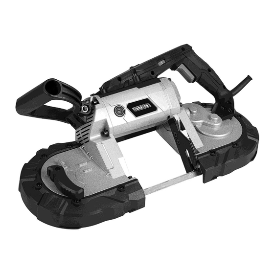
Page 8: Main Parts Of Band Saw
draw. An undersized cord will cause a drop in line voltage, resulting in loss of power and cause overheating. • Be sure your extension cord is properly wired and in good condition. Always replace a damaged extension cord or have it repaired by a qualified person before using it. Protect your extension cords from sharp objects, excessive heat and damp or wet areas. -
Page 9: Assembly Instructions
Subassembly Tension handle (A) External carbon brush (B) Auxiliary handle (C) Motor housing (D) Speed dial (E) On/Off switch (F) Guide bar (G) Blade (H) Screw (I) Guide bearing (J) LED on/off switch (K) LED Light (L) Assembly Instructions ⚠WARNING •... - Page 10 Installing Blades 1. Position the blade so that the teeth are on the bottom and angled toward the work stop, as shown in Figures 1 and 3. 2. Slip the blade into the guide bearing (J), as shown in Figure 2. 3.
-
Page 11: Before Each Use
Before Each Use ⚠WARNING • Always check that the supply voltage is the same as the voltage indicated on the rating label of the tool. Operating Instructions ⚠DANGER • Keep hands and other body parts clear of the cutting blade. Contact with the blade will result in serious injury. -
Page 12: Maintenance
• Set the guide bar against the workpiece, keeping the blade at a 90° angle. • Tilt the unit so that the blade is vertical (as shown below). To start a cut, use minimal force to start a groove. Once the groove is started, allow the rest of the blade to cut into the workpiece. This will prevent the blade from moving from side-to-side while cutting. -
Page 13: Troubleshooting
Maintenance Interval Maintenance Point operate freely. 7. Replace the carbon brush covers. Do not overtighten. Note: When first used, new carbon brushes tend to spark until they wear and conform to the motor’s armature. Regularly inspect and tighten all mounting screws and knobs. - Page 14 Failure Possible Cause Corrective Action 2. Keep blades sharp. Replace as 2. Blade dull or damaged. needed. Excessive noise Internal damage or wear. (Carbon Have technician service tool. or rattling. brushes or bearings, for example.) 1. Forcing tool to work too fast. 1.
-
Page 15: Parts Diagram
Parts Diagram Page 15 of 19... -
Page 16: Parts List
Parts List Part Number Part Description Quantity Sub handle Screw M8X14 Anti-loose screw M6 Handle base Screw M8×70 Light back cover LED light LED cover Light base Screw M4×8 Left handle Speed controller Switch Right handle Sleeve Cable Cable plate Screw M4×16 Screw M4×12 Adjustable wrench... -
Page 17: Replacement Parts
Part Number Part Description Quantity Holder Screw Nut M6x11 Adjusting support Screw M6×20 Wheel Extension spring Movable support Driving shaft Locating sleeve Drive plate Non-slip band Copper bush Dust-proof washer Circlet Φ16 Drive plate cover Needle bearing Class II gear Class III gear shaft Class III gear Collar φ35... -
Page 18: Limited Warranty
Northern Tool and Equipment Company, Inc. ("We'' or ''Us'') warrants to the original purchaser only (''You'' or ''Your'') that the Ironton product purchased will be free from material defects in both materials and workmanship, normal wear and tear excepted, for a period of one year from date of purchase. - Page 19 Distributed by: Northern Tool & Equipment Company, Inc. Burnsville, Minnesota 55306 www.northerntool.com Made in China Page 19 of 19...
Need help?
Do you have a question about the 73134 and is the answer not in the manual?
Questions and answers