
Subscribe to Our Youtube Channel
Related Manuals for Cabletron Systems FDMMIM


Summary of Contents for Cabletron Systems FDMMIM
- Page 1 FDMMIM, FDMMIM-04, FDMMIM-24, and FDMMIM-30 FDDI CONCENTRATOR ETHERNET to FDDI BRIDGE MODULES INSTALLATION and USER’S GUIDE The Complete Networking Solution Cabletron Systems, P. O. Box 5005, Rochester, NH 03867-0505...
- Page 2 Printed in the United States of America Part number: 9030670-03 July 1994 Multi Media Access Center, SPECTRUM, Remote LANVIEW, and LANVIEW are registered trademarks and FDMMIM, FDMMIM-04, FDMMIM-24, FDMMIM-30, FDCMIM-04, FDCMIM-08, FDCMIM-24, FDCMIM-28, IRM, IRM-2, IRM-3, IRBM, EMME, TRMM, CXRMIM, TPRMIM, FORMIM, Flexible Network Bus, MMAC-3FNB, MMAC-5FNB, MMAC-8FNB, and MMAC-M8FNB are trademarks of Cabletron Systems, Inc.
-
Page 3: Fcc Notice
FCC NOTICE FCC NOTICE This device complies with Part 15 of the FCC rules. Operation is subject to the following two conditions: (1) this device may not cause harmful interference, and (2) this device must accept any interference received, including interference that may cause undesired operation. NOTE: This equipment has been tested and found to comply with the limits for a Class A digital device, pursuant to Part 15 of the FCC rules. - Page 4 CLASS 1 LASER TRANSCEIVERS LASER PRODUCT Class 1 Laser Products The FDMMIM-30 connectors use Class 1 Laser transceivers. Read the following safety information before installing or operating the FDMMIM-30. The Class 1 laser transceivers use an optical feedback loop to maintain Class 1 operation limits.
- Page 5 FCC NOTICE SAFETY INFORMATION CLASS 1 LASER TRANSCEIVERS Laser Radiation and Connectors When the connector is in place, all laser radiation remains within the fiber. The maximum amount of radiant power exiting the fiber (under normal conditions) is -12.6dBm or 55x10 -6 watts. Removing the optical connector from the transceiver allows laser radiation to emit directly from the optical port.
-
Page 6: Table Of Contents
Bridging Modules ...1-4 1.4 FDMMIM Features ...1-7 CHAPTER 2 INSTALLING THE FDMMIM 2.1 Before you Install the FDMMIM ..2-1 2.1.1 Adding MIMs to an MMAC ...2-2 2.1.2 MMAC Configurations ...2-4 2.1.3 IRM-3 and Ethernet MIMs with FDMMIMs ...2-4 2.1.4 EMME and RMIMs with an FDMMIM ...2-5... - Page 7 6.3.1 TFTP Code Download Setup Screen Data ...6-10 6.3.2 TFTP Code Download Setup Screen Commands ...6-10 6.4 Image File Download with UNIX ...6-11 6.5 Forcing an Image File Download ...6-13 6.5.1 Forcing a Download with FDMMIM/LM ...6-13 6.5.2 Forcing a Download with BOOTP ...6-14...
- Page 8 CHAPTER 7 SPANNING TREE 7.1 The Bridge Protocol Screen ...7-1 7.1.1 Bridge Protocol Screen Data ...7-2 7.1.2 Bridge Protocol Screen Commands ...7-5 7.2 The Bridge Port Parameters Screen ...7-5 7.2.1 Bridge Port Parameters Screen Data ...7-6 7.2.2 Bridge Port Parameter Screen Commands ...7-7 CHAPTER 8 THE FILTERING DATABASES 8.1 Bridge Operation ...8-1 8.2 The Filter Database Screen ...8-2...
- Page 9 CONTENTS APPENDIX A FDMMIM/LM MESSAGES Information Messages ...A-1 Warning Messages ...A-1 Error Messages ...A-9 APPENDIX B SPECIFICATIONS APPENDIX C BASIC FDDI NETWORKS Basic FDDI Concepts ...C-1 FDDI Media Access Protocol ...C-1 Reliability ...C-3 ANSI Standard X3T9.5 ...C-4 FDDI Connection Rules ...C-8 FDDI Devices ...C-9...
-
Page 10: Chapter 1 Introduction
The FDMMIM, FDMMIM-04, and the FDMMIM-24 A and B ports are multimode fiber optic devices. • The FDMMIM-30 is a single mode fiber optic module that uses a class 1 laser. This laser increases the link length from the multimode maximum drive distance of 2 kilometers (km) to a single mode maximum of 40 km. -
Page 11: Using This Manual
1.1 USING THIS MANUAL You should have a general working knowledge of FDDI networks and the ANSI X3T9.5 standard prior to installing the FDMMIM. (If you need a review of FDDI, see Appendix C.) The following summarizes the organization of this manual. - Page 12 Chapter 6, Setting Up the FDMMIM, explains the following Local Management screens: Setup Community Names Table TFTP Code Download Setup This chapter also provides basic TFTP code downloading instructions, and guidelines for setting up a UNIX workstation to handle an image file download.
-
Page 13: Getting Help
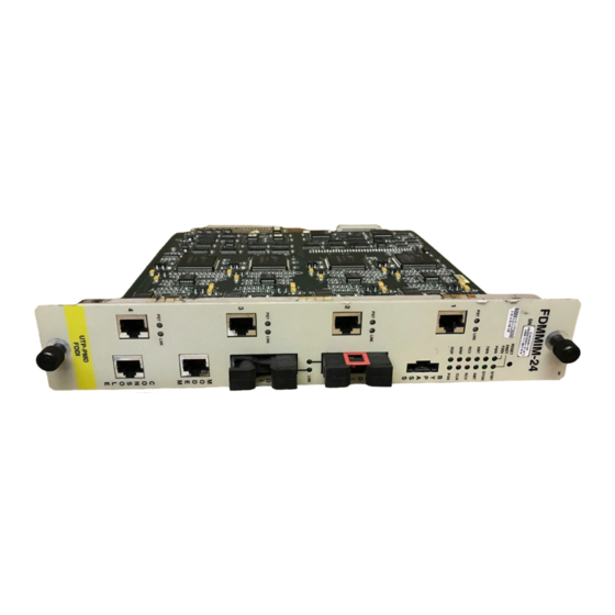
1.3 THE FDMMIM FDDI CONCENTRATOR AND ETHERNET TO FDDI BRIDGING MODULES The FDMMIM provides an ANSI X3T9.5 and IEEE 802.1d compliant media interface that connects an Ethernet and FDDI network using translation bridging. It contains the A and B ports of a modular Dual Attached Station (DAS) or Dual Attached Concentrator (DAC). - Page 14 SYOK LINK FDDI FDDI Figure 1-1. FDMMIM Modules Local Management for the FDMMIM provides module and network information such as frame counts, error breakdowns, and bridge information. You can view LM on a Digital Equipment Corporation VT220 or VT320 terminal, or a PC with terminal emulation software.
- Page 15 INTRODUCTION The FDMMIM can accept an Optical Bypass Switch (Figure 1-2). If you use this optional device, the fiber optic connections pass through the switch, automatically switching to a bypass mode. This feature maintains ring continuity, if the bridge module loses power.
-
Page 16: Fdmmim Features
LANVIEW LANVIEW is a visual diagnostic and status monitoring system developed by Cabletron Systems. LEDs on the FDMMIM front panel indicate the status of the FDMMIM and can help identify module and physical layer problems. Hot Swapping Like all Cabletron Systems Media Interface Modules, you can remove the FDMMIM from, and insert it into, an MMAC without turning off the power to the rest of the modules in the hub. - Page 17 SNMP network management tools such as Cabletron Systems’ SPECTRUM products. Shared Memory The FDMMIM has 4 Mbytes of DRAM buffer memory which it uses for storing data frames. The on-board processor and other support logic also use this memory. Local Memory...
-
Page 18: Chapter 2 Installing The Fdmmim
CHAPTER 2 INSTALLING THE FDMMIM The FDMMIM is a media interface module (MIM) that fits into a Cabletron Systems MMAC network hub. You can install the FDMMIM in any MMAC slot except for slot 1 (the right-most slot). This chapter describes: •... -
Page 19: Adding Mims To An Mmac
2.1.1 Adding MIMs to an MMAC The following examples provide only a sampling of possible MIM and MMAC combinations. Refer to Appendix B for a list of FDMMIM and FDCMIM power requirements. In addition, when configuring an MMAC, remember the following: •... - Page 20 Figure 2-3 represents an MMAC-M8FNB equipped with a full complement of power supplies, two FDCMIM-08s, and one FDMMIM-04. The MMAC power supplies produce up to 80 amps of power, providing more than double the power necessary for operation. This configuration provides redundant power to the hub.
-
Page 21: Mmac Configurations
2.1.2 MMAC Configurations The FDMMIM can bridge FDDI and Ethernet. Since the Ethernet interface to the FDMMIM is through an MMAC Ethernet bus, the bridging function requires that you have both Ethernet and FDDI modules in the same MMAC. To help you configure your MMAC, consider two common MMAC configurations: •... -
Page 22: Emme And Rmims With An Fdmmim
FDDI FDDI Figure 2-4. FDDI and Ethernet MIMs in the Same Hub 2.1.4 EMME and RMIMs with an FDMMIM The EMME, a narrow Ethernet management module, works with the repeater interface controller family of MIMs (RMIM): TPRMIM, CXRMIM, and FORMIM. RMIMs can take full advantage of the MMAC’s Flexible Network Bus (FNB), making them unique. - Page 23 2.2.1 Setting Jumpers Your FDMMIM uses a Nicad battery to maintain power to the RAM in the event of power loss. The RAM holds all bridge configuration data. To prevent the battery from discharging during shipment, the factory sets the battery jumper to the disabled position.
-
Page 24: Installing The Fdmmim
FDMMIM, LM settings default to their corresponding configuration switch settings. Locate the switch bank along the top edge of the FDMMIM and FDMMIM-30 (Figure 2-5). On the FDMMIM-04 and FDMMIM-24, the switch bank resides just below the daughter board containing the M type ports. - Page 25 INSTALLING THE FDMMIM Figure 2-6 shows the general location of the switch bank and the configuration switch options. Note: The FDMMIM is shipped with all switches in the ON position. 1. ON - Forward broadcast packets OFF - Filter broadcast packets 2.
-
Page 26: Installing Into The Mmac
1. Turn off the power to the MMAC. Remember that MMACs with multiple power supplies have an On/Off switch for each supply. 2. Holding the FDMMIM by the front panel or by the edges of the circuit board, align the bottom and top edges of the card with the slot guides in the MMAC chassis. -
Page 27: Connecting Fiber Optic Cabling
You can install the FDMMIM as a Dual Attached Station (DAS), with or without an optical bypass switch. Figure 2-8 illustrates the main ring cabling to the FDDI A and B ports on the FDMMIM. Figure 2-9 shows the duplex cable connections to the A and B ports. - Page 28 The Optical Bypass Switch (also known as a Station Bypass Switch or a Bypass Relay) is an X3T9.5 compliant device that automatically isolates the FDMMIM from the ring if the FDMMIM fails or the FDMMIM power source fails. The bypass switch is optional. If you use this optional device, you should remember the following: •...
- Page 29 Otherwise, begin with step 3. Note: If you install the bypass switch with the FDMMIM powered-up, it can take up to five seconds before the FDMMIM recognizes the switch. 1. Attach the main ring cables to the optical bypass switch by inserting the A and B duplex connectors into their respective keyed receptacles on the optical bypass switch.
-
Page 30: Fdmmim-04 And Fdmmim-24 Master Port Cable Connections
Figure 2-10. Bypass Switch Cable Configuration 2.4 FDMMIM-04 AND FDMMIM-24 MASTER PORT CABLE CONNECTIONS The FDMMIM-04 and FDMMIM-24 have four M type concentrator ports. The FDMMIM-04 ports are fiber connections (keyed green), and the FDMMIM-24 ports are Unshielded Twisted Pair connections. -
Page 31: Master Ports And Lanview
INSTALLING THE FDMMIM RJ-45 TP-PMD PORT Contact Caution: Ground only one end of an STP segment. For Cabletron TP-PMD products, the port casing is grounded. Figure 2-11. TP-PMD Port Pinouts 2.6 MASTER PORTS AND LANVIEW Each master port has two LEDs — PST and LNK. These LEDs show the status of that M type port. -
Page 32: Fdmmim And Lanview
2.7 FDMMIM AND LANVIEW LANVIEW gives you a window into the physical layer of your network. The FDMMIM has two sets of system/bridge LEDs. One set indicates activity on the Ethernet side of the bridge, the other set of LANVIEW LEDs shows FDDI information. - Page 33 INSTALLING THE FDMMIM STBY (STANDBY) When ON, this amber LED indicates that the FDMMIM is in Standby mode. During power-up with STA disabled, the FDMMIM is in Standby mode for approximately 15 seconds, learning addresses, before going on line. During power-up with STA enabled, the bridge...
-
Page 34: Fddi Leds
2.7.2 FDDI LEDs Figure 2-12 shows the six FDDI LEDs on the front of the FDMMIM. ENET FDDI Figure 2-12. LANVIEW FDDI LEDs PWR (POWER) When ON, this green LED indicates that the FDMMIM is receiving power from the MMAC. - Page 35 INSTALLING THE FDMMIM WRP (WRAP) This red LED illuminates when the FDMMIM detects an FDDI ring wrap, meaning that there is a break in the ring, and the system has combined the primary and secondary rings into one ring. ROP (RING OP) When ON, this green LED indicates that the Token Claim Process has completed successfully and the FDDI ring is operational.
-
Page 36: Chapter 3 Connecting To Local Management
• Manually resetting the FDMMIM. 3.1 CONNECTING A CONSOLE Access LM through the RJ-45 CONSOLE port on the FDMMIM front panel. This port supports asynchronous communication through a Digital Equipment Corporation (DEC) VT220 or VT320 terminal, or a PC emulation of one of these terminals. - Page 37 CONNECTING TO LOCAL MANAGEMENT If you have a VT220 or VT320 series terminal, press F3 (Set-Up) to access the Setup Directory and set the options as follows: Display Set-Up Menu Columns Controls Auto Wrap Text Cursor General Set-Up Menu Mode Cursor Keys Communications Set-Up Menu Transmit...
- Page 38 1. Using the components of the Console Cable Kit, connect the RJ-45 end of the RS-232 cable to the port labeled CONSOLE on the FDMMIM. 2. Connect the other end of the RS-232 cable into the COMM port on the terminal or a communication port on a PC. The Console Cable Kit contains adapters to connect to either a DB-9 or DB-25 port.
-
Page 39: Powering-Up The Fdmmim: Diagnostic Tests
CONNECTING TO LOCAL MANAGEMENT Note If you turn on the FDMMIM while you are viewing Local Management, you first see the FDMMIM power-up diagnostics, and then the Password screen appears. If the FDMMIM is already on, the Password screen appears. - Page 40 When the FDMMIM transmits or receives frames via the primary or secondary FDDI network ring, the frames must pass through the FDMMIM A or B ports. The FDDI A and B tests check the hardware components that control communications through the FDMMIM A and B ports.
-
Page 41: Manually Resetting The Fdmmim
Downloads the code in FLASH memory to RAM • Runs its power-up diagnostic tests. Resetting the FDMMIM has the same effect as turning the MMAC power off and on, except that it does not affect any of the other modules in the MMAC. -
Page 42: Chapter 4 Getting Started With Fdmmim Local Management
Local Management default values, and where you can change these values. 4.1 UNDERSTANDING THE SCREENS AND COMMANDS Local Management lets you control FDMMIM bridge parameters and ports of adjacent FDDI modules. To change a setting: • Open the appropriate screen •... -
Page 43: Using The Management Keyboard
GETTING STARTED WITH FDMMIM/LM 4.2 USING THE MANAGEMENT KEYBOARD Use the keyboard arrows (up, down, left, and right) to highlight a command or field (you can only highlight changeable fields). Local Management rejects an incorrect entry, and displays a message that explains the problem. -
Page 44: Screen Organization
GETTING STARTED WITH FDMMIM/LM PASSWORD SCREEN Access FDMMIM Local Management screens. SYSTEM INFORMATION View FDMMIM status and network activity; Access all major LM screens. MESSAGE LOG History log showing warning and error messages reported by LM. NETWORK TRAFFIC Ethernet and FDDI packet counters. - Page 45 Note: Other chapters that refer to specific screens do not repeat this information. Appearing in All Screens Date and time displays the FDMMIM date and time. To change the date and time, go to the Setup screen. Title describes the screen purpose, such as SETUP, or the type of information that the screen provides, such as NETWORK TRAFFIC.
- Page 46 GETTING STARTED WITH FDMMIM/LM Detect Non-Op-Dup Ring-Op-Dup Directed Trace Status/Bridge Status indicates the current status of the FDMMIM. Three potential status conditions could appear in this field: On-Line Standby Disabled The claim (beacon) process of the FDDI ring protocol has exceeded 1 second.
-
Page 47: Data Sections And Command Menus
The default location is Local. Last Reset provides the date and time the FDMMIM was last reset. Restarts provides the number of times the FDMMIM has experienced a restart/power cycle since its battery was enabled. -
Page 48: Setting Fdmmim Operating Parameters
4.5 SETTING FDMMIM OPERATING PARAMETERS Tables 4-1 and 4-2 list, in alphabetical order, each changeable FDMMIM parameter. In addition, the tables also provide the default setting, allowed range, and name of the Local Management screen where you can edit the parameter. - Page 49 GETTING STARTED WITH FDMMIM/LM FDDI port - 80 (0 to FF) Screen Refresh Time 2 seconds (1 to 999 sec.) Type of STA Protocol 802.1 (802.1, DEC, None) Setup Table 4-1. FDMMIM Defaults Parameter Default (Range) Community Names Basic Read - public...
-
Page 50: Chapter 5 Using The Information Screens
INFORMATION SCREENS This chapter concentrates on the data sections and command menus of the Local Management information screens. These screens provide status information on FDMMIM functions. This chapter includes data and command information on the following screens: • System Information •... -
Page 51: Network Traffic Data
5.1.1 NETWORK TRAFFIC Data NETWORK TRAFFIC gives you a summary of frame activity since the last time the FDMMIM was reset or the counters cleared. Traffic statistics ignore frame type (Ethernet or FDDI). See section 5.2 for information on the Network Traffic screen. -
Page 52: Fddi Data
Ring Op Count keeps track of the number of times the FDDI ring has initialized since the last time the FDMMIM was reset. If this number grows steadily, it means that the ring is unstable. MAC Configuration describes the current configuration of the MAC and physical layers of the A and B ports. - Page 53 USING THE INFORMATION SCREENS Wrap-A Note: Dotted line indicates unused path or connection. Wrap-B Note: Dotted line indicates unused path or connection. Isolated Note: Dotted line indicates unused path or connection. PHY-A is wrapped via the MAC (from PHY-A/Primary In to MAC to Secondary Out/PHY-A).
-
Page 54: Filter Database Data
Tnotify is the interval (in seconds) at which an FDMMIM transmits Neighbor Information Frames (NIFs). The station uses NIFs to periodically announce its address and basic station description. -
Page 55: Bridge Protocol Data
10 and 1 million seconds. Dynamics are those addresses that the bridge learns from network traffic. The FDMMIM does not retain Dynamic entries in its memory, in the event it loses power, is turned off, or is reset. Statics are addresses that the FDMMIM copies from the Permanent Database to the Acquired Database when the Acquired Database initializes. - Page 56 USING THE INFORMATION SCREENS Ethernet Port and FDDI Port display the port state of the respective bridge ports. The possible port states include: DISABLED LEARNING LISTENING FORWARDING BLOCKING Bridge Priority displays the part of the bridge address containing the identifier. Spanning Tree uses this identifier for priority comparisons.
-
Page 57: System Information Screen Commands
USING THE INFORMATION SCREENS 5.1.5 System Information Screen Commands The System Information screen is the starting point for any activity in Local Management. The System Information screen contains the following commands: MESSAGE LOG opens the Message Log screen to display all messages, warnings, and errors reported by Local Management. -
Page 58: The Network Traffic Screen
USING THE INFORMATION SCREENS 5.2 THE NETWORK TRAFFIC SCREEN The Network Traffic screen provides a detailed breakdown of the information provided in the Network Traffic section of the System Information screen. Below the header information (described in Chapter 4), the Network Traffic screen data section shows frames and error counts for both the Ethernet port and the FDDI port. -
Page 59: Network Traffic Screen Data
The Network Traffic screen displays the following: Received shows the total number of frames received by the FDMMIM at each bridge port. The totals include both data and Bridge Protocol Data Unit (BPDU) frames. Filtered shows the total number of frames NOT passed from one bridge port to the other, because the frame’s destination was located... - Page 60 USING THE INFORMATION SCREENS Rx Overflow Shows the number of frames lost due to a lack of buffer memory space. An overflow condition is usually due to a high traffic level and collision rate on the Ethernet network. The bridge’s buffer memory space fills while the bridge is waiting to make valid transmissions to the Ethernet or...
-
Page 61: Network Traffic Screen Commands
Note: When you reset the counters, you reset ALL Local Management counters to zero, including those displayed on the System Information screen. This also affects the information displayed by an SNMP remote management tool, since the FDMMIM is the source for MMAC FDDI information. 5-12... -
Page 62: The Ring Map Screen
USING THE INFORMATION SCREENS 5.3 THE RING MAP SCREEN The FDDI Ring Map screen shows FDDI formatted addresses of ring stations in a graphic illustration of the FDDI ring topology, and provides access to a Node Information screen for each device. To display the Ring Map: •... -
Page 63: Ring Map Screen Data
The FDDI Ring Map shows the address and sequence of each FDDI device attached to the ring. When first displayed, the station at the upper left corner of the ring is this station (FDMMIM). The screen displays node class, node address, and twisted and/or wrapped conditions (T for twisted and/or W for wrapped) in parentheses. -
Page 64: Ring Map Screen Commands
3. Press RETURN. The Ring Map scrolls n number of shifts. The scroll number remains the same until you change it, or leave and re-enter FDMMIM Local Management. key (to 5-15... -
Page 65: The Node Information Screen
USING THE INFORMATION SCREENS 5.4 THE NODE INFORMATION SCREEN The Node Information screen provides information for each selected node on the FDDI Ring Map. Note: The Node Information screen reflects node status at the time the node was selected. The Node Information screen does not change dynamically with network adjustments. - Page 66 Master Count shows the number of master ports controlled by the selected node. This number includes any master ports on the selected node (i.e., FDMMIM-04) as well as the ports of all contiguous FDCMIMs that reside to the left of the selected node in the MMAC.
-
Page 67: The Message Log Screen
Error The Message Log is non-volatile; the FDMMIM retains log entries even if you reset the FDMMIM or turn off the power. This function makes it possible to see the log recording of an error that caused the FDMMIM to reset. - Page 68 Date Time Message 10 07/04/94 08:43:11 WARNING: A-A connection accepted 9 07/04/94 08:43:00 MESSAGE: FDMMIM Selftest Complete 8 07/04/94 08:42:22 WARNING: A-A connection accepted 7 07/04/94 08:42:11 MESSAGE: FDMMIM Selftest Complete 6 07/04/94 08:34:29 WARNING: M-M connection rejected 5 07/04/94 08:32:27 WARNING: B-B connection rejected...
-
Page 69: Message Log Data
USING THE INFORMATION SCREENS 5.5.1 Message Log Data The Message Log screen displays the following information: Total Messages is a counter that indicates the number of entries currently held in the log. The log can hold up to 10 messages. The Message Log screen displays up to 10 log entries. -
Page 70: Chapter 6 Setting Up The Fdmmim
CHAPTER 6 SETTING UP THE FDMMIM This chapter explains the screens that let you customize FDMMIM default settings: • Setup • Community Names Table • TFTP Code Download Setup In addition to explaining the TFTP Code Download Setup screen, this chapter provides basic downloading instructions, and guidelines for setting up a UNIX workstation to handle an image file download. -
Page 71: Setup Screen Data
6.1.1 Setup Screen Data The Setup screen contains the following information: Last Reset indicates how long the FDMMIM has been running since the last power interruption. The Last Reset field defaults to the current date and time under the following conditions: •... - Page 72 SETTING UP THE FDMMIM Restarts is a counter that tracks the number of times that the FDMMIM has been reset since the last time FDMMIM was powered- up. If this number grows steadily, it may indicate a hardware problem with the FDMMIM or the MMAC.
- Page 73 Date - MM/DD/YY Time - HH:MM:SS (The default settings are indeterminate. The internal calendar and clock begin running as soon as you activate the FDMMIM battery during installation.) Set IP Address shows the Internet Protocol address currently assigned to the bridge. You can set this field according to your network requirements.
- Page 74 SETTING UP THE FDMMIM FDMMIM Slot Location is a toggle choice that lets you define, to Local Management, the MMAC slot location of the FDMMIM. (Default = SLOT 2. Slot 1, the farthest right MMAC slot, houses only half-width management modules. Available toggle choices depend on the Chassis Type field setting.
-
Page 75: Setup Screen Commands
ENABLE BRIDGE enables the bridging function of the FDMMIM. DISABLE BRIDGE lets you disable the bridge function of the FDMMIM. The FDMMIM still functions as an FDDI DAS or DAC, but does not pass data between the two bridge ports. -
Page 76: The Community Names Table Screen
6.2 THE COMMUNITY NAMES TABLE SCREEN The Community Names Table screen allows you to set access privileges for local and remote management access to the FDMMIM. The SUPER-USER community name acts as the Local Management password. BASIC READ/READ ONLY, and READ-WRITE/SUPER- USER Community names provide different access privileges in remote management. -
Page 77: Community Names Table Screen Data
BASIC READ READ-WRITE SUPER-USER To control remote access to the FDMMIM, edit the Community Names list. Each of the four Community Names is a password that you must enter into a remote access tool before it can gain access to the FDMMIM information and management functions. -
Page 78: Community Names Table Screen Commands
Protocol (TFTP). The TFTP Code Download Setup screen lets you define the location of the system that holds the download file and direct the download to place the new code into the FDMMIM’s RAM, the FLASH EEPROM, or both. (Refer to section 6.4, Image File Download with UNIX, or to your specific remote management documentation for downloading instructions/guidelines.) -
Page 79: Tftp Code Download Setup Screen Data
Filename is a text field where you specify the pathname to and the file name of the new FDMMIM software. The Filename field can hold up to 69 characters. 6.3.2 TFTP Code Download Setup Screen Commands RETURN closes the TFTP Code Download screen, and returns you to the Setup screen. -
Page 80: Image File Download With Unix
(e.g., 00:00:1d:12:12:ce fdm). Note: Colons replace dashes in the ethernet address. 2. Edit the /etc/hosts file by adding the FDMMIM IP address and follow it with the same unique name you used in step #1 (e.g., 132.177.118.24 fdm). - Page 81 Note: You must request a process status and grep for inetd to obtain the process ID number (see step 3 above). 9. Force the download using either FDMMIM/Local Management, or the FDMMIM BOOTP switch. 6-12 12:00 grep rarpd...
-
Page 82: Forcing An Image File Download
Refer to specific package documentation for image file download procedures. 6.5.1 Forcing a Download with FDMMIM/LM Use the following instructions to force a download through FDMMIM Local Management. Using a VT220/VT320 (or emulator), access FDMMIM/LM: 1. Highlight the Setup screen Download option and press Enter. -
Page 83: Forcing A Download With Bootp
1. Unscrew the knurled knobs at the top and bottom of the FDMMIM front panel. 2. Slide the MIM out of the chassis until you can easily access the FDMMIM switch panel located at the top of the mother board. (See Figure 6-4.) Top of Module FDMMIM Switch FDM 01.02.00... - Page 84 Note: The FDMMIM boot PROM must recognize the switch position change to use BOOTP. This means, you must power-up the FDMMIM at least one time (i.e., since taking it out of the shipping package), with its battery enabled, for the device to load initial switch positions into memory.
-
Page 85: Chapter 7 Spanning Tree
The Spanning Tree Algorithm (STA) is the method by which multiple bridges in a network coordinate their activities. This chapter explains how you can control FDMMIM participation in the network STA operation. The two Local Management screens that affect Spanning Tree activities are: •... -
Page 86: Bridge Protocol Screen Data
The Bridge Protocol screen contains information about the network’s Root bridge and about the FDMMIM. Bridge ID is the unique bridge identifier for the FDMMIM. The Bridge ID is computed from the bridge address and the bridge priority, which is explained later in this section. STA compares Bridge IDs to determine the relative priority of the bridges in the network when selecting a Root bridge. - Page 87 Spanning Tree operation to select a new Root. The Bridge Max Age is set by the Root bridge. You can edit the Bridge Max Age value but, unless the FDMMIM is the Root bridge, the new value has no effect. The new value becomes effective only when the FDMMIM becomes the Root.
- Page 88 Bridge Hello Time indicates, in seconds, the length of time the Root bridge waits before resending a Configuration BPDU. You can edit the Bridge Hello Time but, unless the FDMMIM is the Root bridge, the new value has no effect. The new value becomes effective only when the FDMMIM becomes the Root.
-
Page 89: Bridge Protocol Screen Commands
7.1.2 Bridge Protocol Screen Commands RETURN closes the Bridge Protocol screen, and returns you to the System Information screen. SAVE saves the STA operating parameters currently displayed on the Bridge Protocol screen. PORT PARAMETERS opens the Port Parameters screen. 7.2 THE BRIDGE PORT PARAMETERS SCREEN The Bridge Port Parameters screen shows the port-specific parameters related to the Spanning Tree protocol, and lets you change the Port Priority and Path Cost. -
Page 90: Bridge Port Parameters Screen Data
SPANNING TREE 7.2.1 Bridge Port Parameters Screen Data Port-specific Spanning Tree information includes: Port Priority shows the port priority portion of the port identifier. The port priority is one of the values used by STA to choose a Root port for the bridge. A lower number indicates a higher priority. (Default = 80. -
Page 91: Bridge Port Parameter Screen Commands
SPANNING TREE Path Cost displays the portion of the total path cost associated with this port. In a parallel bridge network, the Spanning Tree Algorithm selects the bridge with the lowest path cost as the Root bridge. Changing a port’s path cost can affect the selection of the Root bridge. -
Page 92: Chapter 8 The Filtering Databases
CHAPTER 8 THE FILTERING DATABASES FDMMIM/LM lets you examine entries in the Acquired, Permanent, and Special Databases. This chapter explains how the FDMMIM bridge uses these databases and how you can view their contents. Local Management gives you access to the Filtering Database through five screens: •... -
Page 93: The Filter Database Screen
THE FILTERING DATABASES • The bridge checks the destination address of the frame to determine how to treat it. If the bridge finds the destination address in its Acquired Database, it knows the frame’s destination network (port). At this point the bridge decides whether to filter or forward the frame: —... -
Page 94: Filter Database Screen Data
04/02/94 05:14:34 Filter Database Ethernet Address: 00-00-1D-06-F9-D6 FDDI Address: 00-00-B8-60-9F-EB Uptime: 10 Days 22 Hours Acquired Database Maximum Entries: 8191 Current Entries: Dynamics: Statics: Dynamic Ageing Time: Type of Filtering: RETURN CREATE ENTRY DELETE ENTRY Figure 8-1. Filtering Database Screen 8.2.1 Filter Database Screen Data The Filter Database screen data section displays status information about the databases, and lets you change both the database Dynamic... -
Page 95: Filter Database Screen Commands
THE FILTERING DATABASES addresses that the bridge loads at start-up. The count never drops below the 17 Permanent Database entries. Dynamic Ageing Time is the length of time, in seconds, that the Acquired Database retains a Dynamic entry. To set the Dynamic Ageing time, highlight the Dynamic Ageing Time field and type a new value. -
Page 96: Display Filter Entries Screen
8.3 DISPLAY FILTER ENTRIES SCREEN The Display Filter Entries screen lets you examine the contents of the Acquired and Permanent Databases. To open the Display Filter Entries screen: • Highlight the DISPLAY ENTRIES command in the Filter Database screen, and press RETURN. 04/02/94 05:14:34 Display Filter Entries... -
Page 97: Display Filter Entries Screen Data
THE FILTERING DATABASES 3. Select the type of entry to display by highlighting the Type field and pressing RETURN to toggle between Dynamic and Static. 4. Highlight the DISPLAY ENTRIES command at the bottom of the screen, and press RETURN. The screen lists up to the first ten addresses that match the selected parameters. -
Page 98: Display Filter Entries Screen Commands
Enet Port defines the action the bridge takes on frames entering the Ethernet port: Relay Filter FDDI Port defines the action the bridge takes on frames entering the FDDI port: Relay Filter 8.3.2 Display Filter Entries Screen Commands RETURN closes the Display Filter Entries screen, and returns you to the Filter Database screen. -
Page 99: Create Filter Entry Screen Data
THE FILTERING DATABASES To open the Create Filter Entry screen: • Highlight the CREATE ENTRY command in the Filter Database screen, and press RETURN. 04/02/94 05:14:34 Create Filter Entry Ethernet Address: 00-00-1D-06-F9-D6 FDDI Address: 00-00-B8-60-9F-EB Uptime: 10 Days 22 Hours Acquired Database Maximum Entries: 8191 Current Entries:... -
Page 100: Create Filter Entry Screen Commands
Action on frame entering Enet Port defines the action the bridge takes on packets entering the Ethernet port. Use the RETURN key to toggle between Forward and Filter: Relay Filter Action on frame entering FDDI Port defines the effect on packets entering the FDDI port. -
Page 101: Delete Filter Entry Screen Data
THE FILTERING DATABASES 04/02/94 05:14:34 Delete Filter Entry Ethernet Address: 00-00-1D-06-F9-D6 FDDI Address: 00-00-B8-60-9F-EB Uptime: 10 Days 22 Hours Acquired Database Maximum Entries: 8191 Current Entries: Dynamics: Statics: RETURN Figure 8-4. Delete Filter Entry Screen 8.5.1 Delete Filter Entry Screen Data Database selects the database containing the entry you want to delete. -
Page 102: Special Database Screen
8.6 SPECIAL DATABASE SCREEN You can store up to ten filter entries in the Special Database. These filters, like those in the Acquired Database, determine if the bridge filters or forwards certain frames. However, the Special Database allows you to define one or more fields to participate in the filter/ forward decision. -
Page 103: Special Database Screen Data
THE FILTERING DATABASES 8.6.1 Special Database Screen Data Enable shows whether or not the associated entry is enabled (filtering frames). Highlight this field and use the RETURN key to toggle between Yes (apply the filter) and No (do not apply the filter). Enet defines the action the bridge takes on frames entering the Ethernet port. -
Page 104: Special Database Screen Commands
THE FILTERING DATABASES Data Field provides the bridge with 16 hex integers to compare to the first 16 hex integers of an incoming frame’s information field. Highlight this field and enter the desired 16 hex integers. An X (wildcard) in any integer position forces a match for that integer. Default Action provides the bridge with an action to take, in the event it cannot find a match within the Special Database. -
Page 105: Chapter 9 Controlling Concentrator Modules And Ports
CHAPTER 9 CONTROLLING CONCENTRATOR MODULES AND PORTS The FDMMIM, and adjacent FDCMIMs, make up a modular dual- attached FDDI Concentrator. This chapter explains how to use the FDDI Configuration screen to enable and disable the FDMMIM concentrator and FDCMIM modules and ports. -
Page 106: Fddi Configuration Screen Data
Chassis Type in the Setup screen takes precedence. For example, if your FDMMIM is physically installed in Slot 7 of an MMAC 8, but you have the Chassis type set to MMAC 3 with a Slot 2 location, the configuration screen shows the FDMMIM in Slot 2 of an MMAC 3. - Page 107 CONTROLLING CONCENTRATOR MODULES AND PORTS FDDI Ring Connection Status, when ON, indicates that the FDMMIM is connected to the FDDI ring. When OFF, the FDMMIM is isolated from the ring. (FDCMIMs do not have A and B connectors.) To connect/disconnect the FDMMIM from the FDDI ring: 1.
-
Page 108: Fddi Configuration Screen Commands
Changing FDMMIM concentrator fields does not change bridge operation. Turning the concentrator OFF, only disconnects M ports. The FDMMIM can still pass packets between the FDDI ring and the Ethernet port. The bridge still participates in Spanning Tree Algorithm functions and is still part of the network. -
Page 109: Information Messages
Connecting an FDDI A port to another A port is undesirable. The FDMMIM supports A-A connections unless your Connection Policy specifies otherwise. Action: If possible, reconnect the FDMMIM’s A port cable to a B port. The FDMMIM supports an A-A connection. A-A connection rejected Cause: Connecting an FDDI A port to another A port is undesirable. - Page 110 Cause: Connecting an FDDI A port to an S port is an undesirable connection. The FDMMIM supports A-S connections. Action: If possible, reconnect the FDMMIM’s A port cable so that it connects to a B port. A-S connection rejected Cause: Connecting an FDDI A port to an S port is an undesirable connection.
- Page 111 The FDMMIM rejects B-S connection when directed to do so by your Connection Policy. Action: If possible, reconnect the FDMMIM’s B port cable so that it connects to an A port. Ageing Time must be greater than or equal to 0 and less than...
- Page 112 If this is an isolated incident, no action is required. If this warning continues, reset Spanning Tree as follows: 1. Open the FDMMIM/LM Setup screen. 2. Highlight Type of STA Protocol and press RETURN until the toggle select NONE appears.
- Page 113 Retype the date. Use all numerical values in the format: MM/DD/YY. Illegal BPDU type Cause: The FDMMIM has received a Bridge Protocol Data Unit of an unknown type. Not all bridges on the network are using the same Spanning Tree Algorithm protocol. Action: Check each bridge in the network.
- Page 114 Reconnect the M port cable to an S port. Message history full Cause: The FDMMIM has 100 entries, the maximum, in the Message log. No more entries can be added. Action: Delete the Message log. Open the Message Log screen and execute the DELETE command.
- Page 115 Contact Cabletron Systems Technical Support. Received BPDU not a (DEC IEEE) BPDU type Cause: The FDMMIM has received a Bridge Protocol Data Unit of an unknown type. Not all bridges on the network are using the same Spanning Tree Algorithm protocol.
- Page 116 FDMMIM/LM MESSAGES smt_mib_set (hex address) failed for this instance Cause: Internal error. Action: Contact Cabletron Systems Technical Support. This entry must be greater than or equal to . . . Cause: You entered a number that is smaller than the numbers that this field can accept.
-
Page 117: Error Messages
FDMMIM operations have been interrupted. These errors usually result in disconnecting one or both bridge ports from the network and require that someone fix the problem condition before the FDMMIM can reconnect. Here is a list of potential messages and recommended resolution actions. - Page 118 FDMMIM/LM MESSAGES BSI MAC_DEVICE_ABORT_REQ_STATUS Cause: Internal error. Action: Contact Cabletron Systems Technical Support. BSI MAC_RESET_REQ_STATUS Cause: Internal error. Action: Contact Cabletron Systems Technical Support. BSI NO_REQ_STATUS Cause: Internal error. Action: Contact Cabletron Systems Technical Support. BSI PART_NONE_REQ_STATUS Cause: Internal error.
- Page 119 Internal error. Action: Contact Cabletron Systems Technical Support. FDDI Port A failed self test Cause: The FDMMIM A port has an internal circuit failure that prevents it from connecting to the ring. Action: Contact Cabletron Systems Technical Support. FDMMIM/LM MESSAGES...
- Page 120 FDMMIM/LM MESSAGES FDDI Port B failed self test Cause: The FDMMIM B port has an internal circuit failure that prevents it from connecting to the ring. Action: Contact Cabletron Systems Technical Support. FDDI Test 1 failed self test Cause: The FDMMIM has an internal circuit failure that prevents it from connecting to the ring.
- Page 121 FNB failed self test Cause: The FDMMIM has an internal circuit failure that prevents it from connecting to the MMAC buses. Action: Contact Cabletron Systems Technical Support. Hardware filter ‘display counter’ timeout Cause: A request to the bridge’s filter database hardware could not be completed.
- Page 122 Contact Cabletron Systems Technical Support. Invalid FDDI receive descriptor Cause: Packet buffering error. Action: No action required. The FDMMIM should discard the packet and continue operation. If this error becomes persistent, contact Cabletron Systems Technical Support. Invalid hardware filter ‘display counter’ response Cause: A request to the bridge’s filter database hardware could not...
- Page 123 Cause: Internal error. Action: Contact Cabletron Systems Technical Support. Received POST/GET/SET cmd while FNB protocol locked Cause: The communication between the FDMMIM and an FDCMIM has been unexpectedly interrupted. Action: Contact Cabletron Systems Technical Support. Reset error Cause: Internal error.
- Page 124 FDMMIM/LM MESSAGES Unexpected interrupt, IRM backplane Cause: Internal error. Action: Contact Cabletron Systems Technical Support. Unexpected interrupt, spurious Cause: Internal error. Action: Contact Cabletron Systems Technical Support. Unknown type Cause: Internal error. Action: Contact Cabletron Systems Technical Support. A-16...
-
Page 125: Operating Specifications
This section lists the operating specifications for all of the FDMMIMs. Cabletron Systems reserves the right to change these specifications at any time, without notice. Fiber Optic Interface Depending on the FDMMIM, interfaces have the following characteristics: Multimode Transmitter Optical wavelength: 1330 nm typical... - Page 126 SPECIFICATIONS Unshielded Twisted Pair Transmitter Amplitude: Rise time: Fall time: Rise/Fall variation: Overshoot: Droop(14 symbols): Unshielded Twisted Pair Receiver (Signal Detect) Assert Time: Deassert Time: Single Mode Transmitter Optical wavelength: 1300 nm typical Optical output: Optical rise time: Optical fall time: Spectral width: Supply current: Single Mode Receiver (Signal Detect)
- Page 127 Cable Types The FDDI Multimode Fiber Physical Layer Medium Dependent (MMF-PMD), Twisted Pair Physical Layer Medium Dependent (TP-PMD), and Single Mode Fiber Physical Medium Dependent (SMF-PMD) standards define FDDI cable requirements as follows: Multimode Fiber (as specified in X3T9.5 / 48 - 84 section 7.1): Core diameter: Cladding diameter: Cable attenuation:...
- Page 128 FDDI Ring Connections You can attach the FDMMIM to the ring as a Dual Attached Station (DAS). The two duplex receptacles (FDDI A and FDDI B) on the front of the FDMMIM are keyed to accept Type A (Primary In/Secondary Out) and Type B (Secondary In/Primary Out) Media Interface Connectors.
- Page 129 0671 is the same as one starting with 9400671. Use the following power consumption numbers to help plan your chassis / MIM configuration. Refer to Chapter 2, Installing the FDMMIM, for information on adding MIMs to an MMAC, and configuring your MMAC with FDDI modules. FDMMIM (SN 0671):...
- Page 130 EN 55022 Class A; and the EMC requirements of EN 50082-1. Note: It is the responsibility of the person who sells the system to which the FDMMIM will be a part to ensure that the total system meets allowed limits of conducted and radiated emissions.
-
Page 131: Appendix C Basic Fddi Networks
APPENDIX C BASIC FDDI NETWORKS This Appendix covers basic Fiber Distributed Data Interface (FDDI) network operation and concepts that are critical to FDDI network design and installation. ANSI Standard X3T9.5 provides greater detail on FDDI access methods and should be referenced whenever more complete information is needed. - Page 132 BASIC FDDI NETWORKS When a station has a frame waiting to transmit, the station captures the token at the next opportunity, transmits the data frame, and then reissues the token. (A Token Holding Timer (THT) controls the maximum length of time that any station may retain the token.) As the data frame circulates around the ring, it is received and repeated by each station on the ring.
-
Page 133: Reliability
Ethernet/802.3 Network Ethernet/802.3 Network FDDI BRIDGE ETHERNET to FDDI Ethernet BRIDGE to FDDI Bridge DUAL ATTACHED CONCENTRATOR Single Attached Stations Figure C-1. Typical FDDI Physical Installation Reliability Since FDDI networks employ a ring topology, the entire network is vulnerable to the frailties of each ring segment and failures of the individual stations. -
Page 134: Ansi Standard X3T9.5
BASIC FDDI NETWORKS CONCENTRATOR 3 PRIMARY RING SECONDARY CONCENTRATOR 2 Figure C-2. Wrapping a Broken Ring ANSI Standard X3T9.5 The X3T9.5 standard is divided into five sections: Station Management (SMT), Media Access Control (MAC), two Physical Layer Medium Dependent (PMD) standards (one for multimode fiber and another, SMF-PMD, for single mode fiber) and a Physical Layer Protocol (PHY). - Page 135 Application Presentation Session Transport Network Data Link Physical Figure C-3. FDDI Structure and the OSI Network Model The PMD standard establishes the physical characteristics of the network connection, including the fiber optic transmitter power levels, receiver sensitivity, the fiber optic cable type, the type of connectors, and acceptable losses between nodes.
- Page 136 BASIC FDDI NETWORKS The MAC entity is the lower sublayer of the Data Link layer. The upper sublayer, Logical Link Control (LLC) serves as an interface between the OSI model and the FDDI network. The MAC element, under control of Station Management, performs many of the tasks associated with frame preparation and media access: ring scheduling, token generation, timers that monitor ring activity, ring initialization, and beaconing.
- Page 137 FDDI STATION Configuration Path Switch Bypass Switch (optional) Figure C-5. SMT Management Organization SMT Frame Services generates and interprets special FDDI frames that are used to control and monitor the network. Ring Management (RMT) monitors status information from the MAC and Configuration Management and controls several functions related to the health of the ring.
-
Page 138: Fddi Connection Rules
BASIC FDDI NETWORKS Connection Management (CMT) controls physical layer insertion and removal of stations. CMT has three main components: • Entity Coordination Management (ECM) controls bypass switches and coordinates trace (recovery) functions. • Configuration Management (CFM) controls how the PHY and MAC entities are configured within a node. -
Page 139: Fddi Devices
BASIC FDDI NETWORKS Port A Port A Port B Port B Port M Port M Port M Port M Backup Primary Port A Port B Connection Connection Figure C-6. Dual Homing Topology Concentrator 3 in Figure C-6 has redundant connections to the main ring through either concentrator 1 or 2. - Page 140 BASIC FDDI NETWORKS Single Attached Concentrator PMD-3 PMD-2 PMD-1 PHY-3 PHY-2 PHY-1 Single Attached Station Figure C-7. Valid Station Configurations FDDI devices are physically attached to the ring using Fixed Shroud Duplex (FSD) media interface connectors. Four connectors are defined in the X3T9.5 Physical Layer, PMD standard (see Figure C-7).
- Page 141 FDDI RECEPTACLES PRIMARY IN SECONDARY OUT TYPE A DUAL ATTACHMENT SECONDARY IN PRIMARY OUT TYPE B TYPE M SINGLE ATTACHMENT TYPE S Figure C-8. Duplex Fiber Optic Receptacles and Connectors Optical bypass switches, concentrators, and bridges are found throughout FDDI networks. These devices are used to create ring topologies to meet the specific needs of different network applications.
- Page 142 BASIC FDDI NETWORKS An optical bypass switch is a device that can be inserted between a station and the FDDI ring connections that lets you remove the station from the ring without disturbing ring continuity. They are usually electrically actuated and provide passive optical switching of both the primary and secondary ring cables.
- Page 143 Bridging devices for FDDI connect multiple FDDI networks and link an FDDI ring to a network that uses a different MAC layer protocol (Token Ring or Ethernet). A bridge does not expand an existing FDDI ring, it connects rings. Bridges used to link two different MAC layer protocols, such as FDDI and Ethernet, typically use one of two bridging techniques, encapsulation or translation.
-
Page 144: Design Considerations For Fddi Networks
BASIC FDDI NETWORKS DESIGN CONSIDERATIONS FOR FDDI NETWORKS The main variables that are of interest to the FDDI network designer are ring length, drive distance (distance between nodes), and the maximum number of stations. While there are many factors that determine the limits set for these design elements, this section examines the ANSI standard and focuses on those factors that you can control in your network. -
Page 145: Attenuation
BASIC FDDI NETWORKS In some multimode applications, existing 50/125 m or 100/140 m fiber can be used over longer distances. However, the cable must conform to the FDDI standard for bandwidth and attenuation to remain compliant with the FDDI standard. Attenuation The maximum attenuation (attenuation budget) between any two active connections to the ring, as defined by the FDDI standard, is 11... - Page 146 BASIC FDDI NETWORKS 16 PHYSICAL CONNECTIONS Figure C-11. Physical Device Connections C-16...
-
Page 147: Index
access levels 6-8 Alignment Errors 5-11 Basic Read 6-8 battery 2-6 back-up RAM 1-8 jumper location 2-7 BLOCKING 5-7, 7-6 bridge configuration switches 2-7 Bridge Forward Delay 7-3 Hello Time 7-3 ID 7-2 Max Age 7-3 Name 4-7, 6-3 Operation 8-1 Priority 5-7, 7-4 Protocol Data Unit 5-3, 5-10... - Page 148 INDEX Disabled 4-6 Display Filter Entries Screen 8-5 downloading 6-9, 6-11 dual attached concentrator 5-14 station 5-14 duplex cable connections 2-11 Dynamic Ageing Time 5-6, 8-4 Dynamics 5-6 EMME 2-5 ENABLE BRIDGE command 6-6 EEPROM, FLASH 1-8 Error 5-18 Errors, Rx 5-10 Ethernet Address 4-5 interface 1-6...
- Page 149 memory Flash EEPROM 1-8 local 1-8 RAM 1-8 shared 1-8 Message 5-18 Bar 4-5 Duration 6-3 Log 4-7 Log capacity 5-19 Log screen 5-19 5-14 Neighbor Information Frames 5-5 Network Name 6-3 Network Traffic screen 5-1, 5-9 Non-Op 4-5 Non-Op-Dup 4-6 None 5-6 Null Attached Station 5-14 On-Line 4-6...
- Page 150 INDEX single attached concentrator 5-14 station 5-14 Slot Location 6-5 SMT 1-5 SNMP 1-4 Source Address Table size 1-8 Spanning Tree Algorithm 5-6, 7-1 Special Database screen 8-11 STA 5-6 Standby 2-16, 4-6 Statics 5-6 station bypass switch 2-12 management 1-5 setup 6-11 Status 4-6...
Need help?
Do you have a question about the FDMMIM and is the answer not in the manual?
Questions and answers