Table of Contents
Advertisement
Advertisement
Table of Contents
Troubleshooting

Related Manuals for Enterasys SmartSwitch 6G302-06


Summary of Contents for Enterasys SmartSwitch 6G302-06
- Page 1 6G302-06 and 6G306-06 Gigabit Ethernet Installation Guide 9033322-01...
- Page 3 Enterasys Networks reserves the right to make changes in specifications and other information contained in this document and its web site without prior notice. The reader should in all cases consult Enterasys Networks to determine whether any such changes have been made.
-
Page 4: Fcc Notice
FCC NOTICE This device complies with Part 15 of the FCC rules. Operation is subject to the following two conditions: (1) this device may not cause harmful interference, and (2) this device must accept any interference received, including interference that may cause undesired operation. -
Page 5: Safety Information
SAFETY INFORMATION CLASS 1 LASER TRANSCEIVERS THE SINGLE MODE INTERFACE MODULES USE CLASS 1 LASER TRANSCEIVERS. READ THE FOLLOWING SAFETY INFORMATION BEFORE INSTALLING OR OPERATING THESE MODULES. The Class 1 laser transceivers use an optical feedback loop to maintain Class 1 operation limits. This control loop eliminates the need for maintenance checks or adjustments. - Page 6 This document is an agreement (“Agreement”) between You, the end user, and Enterasys Networks, Inc. (“Enterasys”) that sets forth your rights and obligations with respect to the Enterasys software program (“Program”) in the package. The Program may be contained in firmware, chips or other media. UTILIZING THE ENCLOSED PRODUCT, YOU ARE AGREEING TO BECOME BOUND BY THE TERMS OF THIS AGREEMENT, WHICH INCLUDES THE LICENSE AND THE LIMITATION OF WARRANTY AND DISCLAIMER OF LIABILITY.
- Page 7 52.227-19 (a) through (d) of the Commercial Computer Software-Restricted Rights Clause and its successors, and (iii) in all respects is proprietary data belonging to Enterasys and/or its suppliers. For Department of Defense units, the Product is considered commercial computer software in accordance with DFARS section 227.7202-3 and its successors, and use, duplication, or disclosure by the Government is subject to restrictions set forth herein.
-
Page 8: Declaration Of Conformity
Manufacturer’s Address: European Representative Address: Conformance to Directive(s)/Product Standards: Equipment Type/Environment: Networking Equipment, for use in a Commercial Enterasys Networks, Inc. declares that the equipment packaged with this notice conforms to the above directives. 73/23/EEC 500 Spaulding Turnpike PO Box 3060 Portsmouth, NH 03801 Enterasys Networks Ltd. -
Page 9: Table Of Contents
Remote Monitoring (RMON) ... 1-5 Broadcast Suppression ... 1-5 Port/VLAN Redirect Functions ... 1-6 Traffic Rate Limiting ... 1-6 Flow Control ... 1-7 GARP Switch Operation... 1-7 1.10 802.1 Port Priority ... 1-7 1.11 Distributed Chassis Management ... 1-8 1.11.1 1.11.2... - Page 10 Using LANVIEW... 4-1 Troubleshooting Checklist... 4-4 Using the Reset Button ... 4-7 SPECIFICATIONS Module Specifications ...A-1 COM Port Pinout Assignments ...A-2 Regulatory Compliance...A-3 MODE SWITCH BANK SETTINGS AND OPTIONS Required Tools...B-1 Setting the Mode Switches...B-2 FLASH Upgrade...B-4 B.3.1 B.3.2 viii Contents Side Clip GPIMs...
- Page 11 GPIM SPECIFICATIONS Gigabit Ethernet Specifications ... C-1 C.1.1 C.1.2 C.1.3 Physical and Environmental Specifications... C-4 Regulatory Compliance... C-4 INDEX GPIM-01 Specifications (1000BASE-SX) ... C-1 GPIM-08 Specifications ... C-2 GPIM-09 Specifications (1000BASE-LX)... C-3 Contents...
-
Page 12: Figures
GPIM-09 Launch Mode Conditioning Cable Connection ... 3-18 3-15 Fiber GPIM Connections... 3-20 3-16 Module Fiber Port LEDs... 3-21 LANVIEW LEDs ... 4-1 RESET Button... 4-7 Mode Switch Location... B-2 FLASH Module Location ... B-4 Installing the FLASH ... B-5 Figures Page... - Page 13 Table GPIM Options ... 1-4 Contents of the Module Carton... 3-2 LANVIEW LEDs... 4-2 Troubleshooting Checklist ... 4-4 Specifications ... A-1 COM Port Pin Assignments ... A-2 GPIM-01 Optical Specifications ... C-1 GPIM-01 Operating Range ... C-2 GPIM-08 Optical Specifications ... C-2 GPIM-08 Operating Range ...
-
Page 15: About This Guide
6G302-06 and 6G306-06 modules and provides information concerning network requirements, installation, and troubleshooting. For information about how to use Local Management to configure and manage the modules, refer to the Enterasys Networks Matrix E7 Series and SmartSwitch 6000 Series Modules Local Management User’s Guide. -
Page 16: Structure Of This Guide
Specifications, lists the operating specifications and regulatory compliance for the GPIMs. RELATED DOCUMENTS The following Enterasys Networks documents may help to set up and manage the module: • Matrix E7 Series and SmartSwitch 6000 Series Modules Local Management User’s Guide •... -
Page 17: Document Conventions
Warning symbol. Warns against an action that could result in personal injury or death. GETTING HELP For additional support related to this device or document, contact Enterasys Networks using one of the following methods: World Wide Web http://www.enterasys.com/... - Page 18 A description of any action(s) already taken to resolve the problem (e.g., changing mode switches, rebooting the unit, etc.) • The serial and revision numbers of all involved Enterasys Networks products in the network • A description of your network environment (layout, cable type, etc.) •...
-
Page 19: Introduction
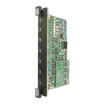
Ether type. Detailed information about VLANs is provided in the local management user’s guide. The modules receive power and backplane connectivity when inserted into an Enterasys Networks’ 6C107 Matrix E7 chassis or 6C105 SmartSwitch 6000 chassis. Important Notice 1-1, View A) features six 1000BASE-T Gigabit Ethernet ports with 1-1, View B) features six Gigabit Ethernet ports. -
Page 20: G302-06 And 6G306-06 Modules
Figure 1-1 6G302-06 and 6G306-06 Modules Introduction... -
Page 21: Connectivity
CONNECTIVITY 6G302-06 The 6G302-06 connects to Gigabit Ethernet networks or workstations through its six RJ45 front panel port connectors. These ports are IEEE 802.3 1000BASE-T compliant, and support the connection of category 5 cables that are up to 100 meters long. 6G306-06 The 6G306-06 has six ports that support Gigabit Ethernet Port Interface Modules (GPIMs), which allow the user to make connections to Gigabit Ethernet networks. -
Page 22: Options
Runtime IP Address Discovery 1.1.1 Options The GPIM options for the module are listed in changes or additions to this information. Table 1-1 GPIM Options Part Number GPIM-01 GPIM-08 GPIM-09 RUNTIME IP ADDRESS DISCOVERY This feature enables the module to automatically accept an IP address from a Boot Strap Protocol (BootP) server on the network without requiring a user to enter an IP address through Local Management. -
Page 23: Smarttrunk
SmartTrunk provides the ability to take full advantage of the network’s redundant bandwidth. SmartTrunk divides network traffic across multiple ports in parallel to provide additional throughput. The SmartTrunk application can be used with any of the Enterasys Networks switch modules (except ATM modules). -
Page 24: Port/Vlan Redirect Functions
VLAN classification of the frames received. Multiple VLANs can be directed to the same destination port. The VLAN redirect function is only supported when the module is operating as an 802.1Q switch. TRAFFIC RATE LIMITING The Traffic Rate Limiting feature allows the module to control traffic rates on a per-port, per-priority basis. -
Page 25: Flow Control
GARP attributes such as VLAN and multicast group membership. For more details on how GVRP and GMRP handle frames under GARP, and how to configure the switch ports to take advantage of this operation, refer to the Matrix E7 Series and SmartSwitch 6000 Series Modules Local Management User’s Guide. -
Page 26: Distributed Chassis Management
1.12 MANAGEMENT Management of the module can be either in-band or out-of-band. In-band remote management is possible through any SNMP compliant Network Management Software, such as Enterasys Networks’ WebView and Aprisma’s SPECTRUM for Open Systems suite of management products. Out-of-band Local Management is provided through the RJ45 COM port on the front panel using a VT100 terminal or a VT100 terminal emulator. -
Page 27: Switching Options
(Bridge MIB), RFC 1354 (FIB MIB), and RFC 1190 (Path MTU Discovery). A full suite of Enterasys Networks’ Enterprise MIBs provide a wide array of statistical information to enhance troubleshooting. For information on how to extract and compile individual MIBs, contact Enterasys Networks. -
Page 29: Network Requirements
NOTE: The Matrix E7 Series and SmartSwitch 6000 Series Modules Local Management User’s Guide referred to in the following sections can be found on the Enterasys Networks World Wide Web site: SMARTTRUNK FEATURE Before connecting the module to a network so it can take advantage of the SmartTrunk feature, there are certain rules concerning port connections and configurations that must be followed for proper operation. -
Page 30: 1000Base-Sx/Lx Network
1000BASE-SX/LX Network 1000BASE-SX/LX NETWORK The removable GPIMs for the 6G306-06 provide a Gigabit Ethernet connection that, when using the GPIM-01, GPIM-08, and GPIM-09, support fiber connections operating at 1000 Mbps (1 Gbps). Other GPIMs may support different types of cabling connections. The device at the other end of the fiber connection must meet IEEE 802.3z Gigabit Ethernet requirements for the devices to operate at Gigabit speed. - Page 31 WARNING: Only qualified personnel should install the 6G302-06 or 6G306-06. NOTE: Read the Release Notes shipped with the module to check for any exceptions to the supported features and operation documented in this guide. Unless otherwise noted, the following instructions apply to both the 6G302-06 and 6G306-06.
-
Page 32: Installation
Manual Accessory Kit 3. Remove the tape seal on the non-conductive bag to remove the module. 4. Perform a visual inspection of the module for any signs of physical damage. Contact Enterasys Networks if there are any signs of damage. Refer to... -
Page 33: Side Clip Gpims
CAUTION: The GPIM and the module are sensitive to static discharges. Use an antistatic wrist strap and observe all static precautions during this procedure. Failure to do so could result in damage to the GPIM or module. Always leave the GPIM in the antistatic bag in which it was shipped or an equivalent antistatic container until ready to install it. -
Page 34: Installing The Side Clip Gpim
Installing Options into the 6G306-06 3.2.1.1 Installing the Side Clip GPIM The GPIMs are installed into the module as follows: 1. Attach the antistatic strap (refer to the instructions in the antistatic wrist strap package) before removing the GPIM from the antistatic packaging. 2. -
Page 35: Removing The Side Clip Gpim
Figure 3-3 Installing a Side Clip GPIM into the Module 3.2.1.2 Removing the Side Clip GPIM CAUTION: Do NOT remove a GPIM from a slot without unlocking the tabs. This can damage the GPIM. The GPIM and the module are sensitive to static discharges. Use an antistatic wrist strap and observe all static precautions during this procedure. -
Page 36: Locking Bar Gpims
Installing Options into the 6G306-06 3.2.2 Locking Bar GPIMs This section describes how to install and remove GPIMs that are equipped with a metal locking bar. Refer to Appendix C for cable specifications for the GPIMs. CAUTION: This section applies only to GPIMs equipped with a metal locking bar. Damage can result to the GPIM and module if the directions in this manual are not followed carefully. - Page 37 If there is significant resistance while attempting to close the locking bar, remove the GPIM. Inspect it for any problems with the connectors. If there are any problems, contact Enterasys Networks for technical support (refer to This Guide).
-
Page 38: Removing The Locking Bar Gpim
Installing Modules into the Matrix E7 Chassis 3.2.2.2 Removing the Locking Bar GPIM CAUTION: Do NOT remove a GPIM from a slot without unlocking the metal locking bar. This can damage the GPIM. The GPIM and the module are sensitive to static discharges. Use an antistatic wrist strap and observe all static precautions during this procedure. - Page 39 Observe all precautions to prevent damage from Electrostatic Discharge (ESD). 5. Examine the module for damage. If any damage exists, DO NOT install the module. Immediately contact Enterasys Networks. Refer to CAUTION: To prevent damaging the backplane connectors in the following step, take care that the module slides in straight and properly engages the backplane connectors.
-
Page 40: Installing The Module In The Matrix E7 Chassis
Installing Modules into the Matrix E7 Chassis Figure 3-6 Installing the Module in the Matrix E7 Chassis 3-10 Installation... -
Page 41: Installing The Module Into The 6C105 Chassis
INSTALLING THE MODULE INTO THE 6C105 CHASSIS CAUTION: Failure to observe static safety precautions could cause damage to the module. Follow static safety handling rules and wear the antistatic wrist strap provided with the 6C105 chassis. Do not cut the non-conductive bag to remove the module. Sharp objects contacting the board or components can cause damage. -
Page 42: Installing The Module In The 6C105 Chassis
Installing the Module into the 6C105 Chassis Figure 3-7 Installing the Module in the 6C105 Chassis 3-12 Installation... -
Page 43: Connecting The 6G302-06 To The Network
CONNECTING THE 6G302-06 TO THE NETWORK This section describes how to connect unshielded twisted pair (UTP) segments from the network or other devices to the 6G302-06 NOTE: If the module is being installed in a network using Port Trunking, there are rules concerning the network cable and port configurations that must be followed for Port Trunking to operate properly. -
Page 44: Connecting A Twisted Pair Segment To The 6G302-06
(computer). Refer to Figure 3-11 Figure 3-12 d. If a link is not established, contact Enterasys Networks. Refer to This Guide for details. 4. Repeat all the steps above until all connections have been made. -
Page 45: Four-Wire Crossover Cable Rj45 Pinouts For 10/100Base-T
Connecting the 6G302-06 to the Network Figure 3-9 Four-Wire Crossover Cable RJ45 Pinouts for 10/100BASE-T Figure 3-10 Four-Wire Straight-Through Cable RJ45 Pinouts for 10/100BASE-T Installation 3-15... -
Page 46: Eight-Wire Crossover Cable Rj45 Pinouts For 10/100/1000Base-T
Connecting the 6G302-06 to the Network Figure 3-11 Eight-Wire Crossover Cable RJ45 Pinouts for 10/100/1000BASE-T Figure 3-12 Eight-Wire Straight-Through Cable RJ45 Pinouts for 10/100/1000BASE-T 3-16 Installation... -
Page 47: Connecting The 6G306-06 To The Network
The GPIM-01, GPIM-08, and GPIM-09 each have an SC style connector for the network port that is used to connect to the Gigabit Ethernet network. Enterasys Networks offers fiber optic cables that use SC style connectors, which are keyed to ensure proper crossover of the transmit and receive fibers. -
Page 48: Gpim-09 Connection Using Multimode Cable
(Section single mode fiber cable to the GPIM-09. Launch Mode Conditioning cables are available from Enterasys Networks. To connect the GPIM-09 to the network using multimode fiber, perform the following steps: 1. Connect Launch Mode Conditioning cable to the multimode fiber on both ends of the multimode cable, before connecting the SmartSwitch with a GPIM-09 to the multimode fiber cabling. -
Page 49: 6G306-06 Network Connection
3.6.3 6G306-06 Network Connection To connect the module using fiber cable to the network, perform the following steps: NOTE: If connecting the module with a GPIM-09 to the network using multimode fiber cable, refer to Section 3.6.2 1. Remove any protective covers from the fiber optic ports and from the ends of the connectors. WARNING: The GPIM-08 and GPIM-09 use Class 1 lasers. -
Page 50: Fiber Gpim Connections
Connecting the 6G306-06 to the Network Figure 3-15 Fiber GPIM Connections 3. At the other end of the fiber optic cable, attach the SC connector to the other device. Verify that a link exists by checking that the port Receive LED is ON (flashing amber, blinking green, or solid green). -
Page 51: Completing The Installation
Series and SmartSwitch 6000 Series Modules Local Management User’s Guide for information on how to access and use Local Management. Chapter 4 for LED troubleshooting details. If a problem in About This Guide for details on contacting Enterasys Completing the Installation Installation 3-21... -
Page 53: Troubleshooting
• Using the RESET Button (Section 4.3) USING LANVIEW The modules use Enterasys Networks’ built-in visual diagnostic and status monitoring system called LANVIEW. The LANVIEW LEDs (Figure 4-1) allow quick observation of the network status to aid in diagnosing network problems. -
Page 54: Lanview Leds
Green Troubleshooting Table 4-1 indicate the following: Recommended Action Ensure chassis has adequate power. Contact Enterasys Networks for technical support. If the LED remains red for several minutes, contact Enterasys Networks for technical support. Contact Enterasys Networks for technical support. - Page 55 Solid. Diagnostic failure. Recommended Action None. None. None. None. Contact Enterasys Networks for assistance. Ensure that the Spanning Tree Algorithm (STA) is enabled and that there is a valid link. None. Ensure that the port is not disabled. None.
-
Page 56: Troubleshooting Checklist
Community Names Table setup. 2. If the Community Names have been forgotten, refer to Section B.2 instructions on how to set the mode switch to reset the Community Names to their default values. 3, and that the host Section B.2... - Page 57 SmartSwitch 6000 Series Modules Local Management User’s Guide for instructions to enable/disable ports. 1. Verify that all network connections between the network management station and the module are valid and operating. 2. If the problem continues, contact Enterasys Networks for technical support. Troubleshooting...
- Page 58 Tree Algorithm (STA). 2. Review the network design and delete unnecessary loops. 3. If the problem continues, contact Enterasys Networks for technical support. 1. Reenter the lost parameters as necessary. Refer to the Matrix E7 Series and SmartSwitch 6000 Series Modules Local Management User’s Guide for the...
-
Page 59: Using The Reset Button
USING THE RESET BUTTON The RESET button shown in CAUTION: Pressing the RESET button resets the device, and all current switching being performed by the module is halted. A module downtime of up to two minutes will result from this action for any devices connected to the module. Figure 4-2 RESET Button To reset the module processor, press and release the RESET button. -
Page 61: Module Specifications
This appendix provides operating specifications for the 6G302-06 and 6G306-06 modules. Enterasys Networks reserves the right to change the specifications at any time without notice. MODULE SPECIFICATIONS Table A-1 provides the I/O ports, processors and memory, physical, and environmental module specifications for the 6G302-06 and 6G306-06. -
Page 62: Com Port Pinout Assignments
COM Port Pinout Assignments Table A-1 Specifications (Continued) Item Physical Dimensions Approximate Weight (Unit) MTBF (Predicted) Environmental Operating Temperature Storage Temperature Operating Relative Humidity COM PORT PINOUT ASSIGNMENTS The COM port is a serial communications port that supports Local Management or connection to an Uninterruptible Power Supply (UPS). -
Page 63: Regulatory Compliance
REGULATORY COMPLIANCE The modules meet the following safety and electromagnetic compatibility (EMC) requirements: Safety: Electromagnetic Compatibility (EMC): UL 1950, CSA C22.2 No. 950, 73/23/EEC, EN 60950, IEC 950, and EN 60825 FCC Part 15, CSA C108.8, 89/336/EEC, EN 55022, EN 61000-3-2, EN 61000-3-3, EN 55024, AS/NZS 3548, and VCCI V-3 Regulatory Compliance Specifications... -
Page 65: Mode Switch Bank Settings And Options
Mode Switch Bank Settings and Options This appendix covers the following items: • Required tools (Section • Locations, functions, and settings for the mode switches • Upgrading the FLASH (Figure REQUIRED TOOLS Use the following tools to perform the procedures provided in this appendix: •... -
Page 66: Setting The Mode Switches
These switches are set at the factory and rarely need to be changed. Switch definitions and positions are as follows: • Switches 1 through 4 – For Enterasys Networks use only. • Switch 5 – COM Port Autobaud. The default (OFF) position enables Autobaud sensing on the COM port for Local Management sessions. - Page 67 (TFTP) server containing the module image file. When the position of Switch 6 is changed and the power is cycled to the module, the device requests the image file location from the BootP server and uses TFTP to download the image from the TFTP server.
-
Page 68: Flash Upgrade
For details on getting help, refer to B.3.1 Locating the FLASH Module Figure B-2 shows the location of the FLASH module. Figure B-2 FLASH Module Location Mode Switch Bank Settings and Options “Getting Help”, in About This Guide. Flash Module Memory Board... -
Page 69: Installing The Flash Module
2. Pivot the FLASH module downward so the connector clips align with the two side notches of the FLASH module and the connector clips lock the FLASH module into place. Figure B-3 Installing the FLASH Figure B-3 and proceed as follows: Figure B-3, insert the FLASH module down Mode Switch Bank Settings and Options FLASH Upgrade... -
Page 71: Gpim Specifications
This appendix lists the specifications and regulatory requirements for the GPIMs and the media they use. Enterasys Networks reserves the right to change these specifications at any time without notice. The available GPIM options are the GPIM-01, GPIM-08, and GPIM-09. All three devices use SC connectors. -
Page 72: Gpim-08 Specifications
Gigabit Ethernet Specifications Table C-2 GPIM-01 Operating Range 62.5 µm MMF 62.5 µm MMF 50 µm MMF 50 µm MMF C.1.2 GPIM-08 Specifications Table C-3 GPIM-08 Optical Specifications Transmit Power (minimum) Receive Sensitivity Link Power Budget Table C-4 GPIM-08 Operating Range 10 µm SMF (1550 nm Wavelength) GPIM Specifications Modal Bandwidth @... -
Page 73: Gpim-09 Specifications (1000Base-Lx
C.1.3 GPIM-09 Specifications (1000BASE-LX) Table C-5 GPIM-09 Optical Specifications Transmit Power (minimum) Receive Sensitivity Link Power Budget Table C-6 GPIM-09 Operating Range 62.5 µm MMF 50 µm MMF 50 µm MMF 10 µm SMF A. In order to obtain the distance of 550 m for the GPIM-09 using multimode fiber, Launch Mode Conditioning cable must be used. -
Page 74: Physical And Environmental Specifications
Physical and Environmental Specifications PHYSICAL AND ENVIRONMENTAL SPECIFICATIONS Physical: Dimensions Weight Environmental: Operating Temperature Storage Temperature Operating Humidity REGULATORY COMPLIANCE The GPIMs meet the following safety and electromagnetic compatibility (EMC) requirements: • 21 CFR 1040.10, 1040.11, and CDRH (U.S. Department of Health and Human Services) (FDA). - Page 75 Numerics 1000BASE-FL requirements 1000BASE-T connection 3-13 1000BASE-T Network Connections requirements for 802.1p Port Priority introduction to GPIM locking Broadcast Suppression introduction to Cable specifications 10BASE-T network COM port pin assignments Connecting to the network 3-13, Connectivity 6G302-06 6G306-06 introduction to Distributed Chassis Management Document conventions FLASH...
- Page 76 Management use of Mode Switch setting Module features 6G302-06 6G306-06 Pinouts crossover 3-15, 3-16 straight-through 3-15, 3-16 Port redirect function introduction to Redirect functions port and VLAN introduction to Regulatory Compliance A-3, Related manuals Remote Monitoring (RMON) introduction to RESET button...
Need help?
Do you have a question about the SmartSwitch 6G302-06 and is the answer not in the manual?
Questions and answers