Table of Contents
Advertisement
SDM630 MOBILE RADIO
USER MANUAL
ISSUE 1.5
Document Number: TNM--U-E-0108
Unrestricted
Date: June 2019
© Simoco Wireless Solutions 2019
Simoco Wireless Solutions
Uttoxeter Old Road,
Tel: +44 (0) 1332 375500
Fax: +44 (0) 1332 375501
www.simocowirelesssolutions.com
Field House,
Derby.
DE1 1NH.
Simoco Wireless Solutions
1270 Ferntree Gully Road,
Scoresby Victoria,
3179
Australia.
Tel: +61 (0)3 9730 3999
Fax: +61 (0)3 9730 3988
www.simocowirelesssolutions.com
Advertisement
Table of Contents

Related Manuals for Simoco SDM600 Series


Summary of Contents for Simoco SDM600 Series
- Page 1 SDM630 MOBILE RADIO USER MANUAL ISSUE 1.5 Document Number: TNM--U-E-0108 Unrestricted Date: June 2019 © Simoco Wireless Solutions 2019 Simoco Wireless Solutions...
- Page 2 This page has been intentionally left blank. Doc Number: TNM--U-E-0108 ISSUE 1.5 Page...
-
Page 3: Preface
EQUIPMENT AND MANUAL UPDATES In the interests of improving the performance, reliability or servicing of the equipment, Simoco Wireless Solutions reserve the right to update the equipment or this document or both without prior notice. Doc Number: TNM--U-E-0108 ISSUE 1.5... -
Page 4: Errors And Omissions
Whilst every endeavour has been made to eliminate any errors, some may still exist. It is requested that any errors or omissions noted should be reported to either of the following who are part of Simoco Wireless Solutions: Doc Number: TNM--U-E-0108 ISSUE 1.5... -
Page 5: Document History
1. TNM-U-E-0110. SDM630 DMR User Guide. 2. TNM-I-E-0038. SDM600 Installation Guide To order printed copies of this or any of the above publications, please contact Simoco Wireless Solutions. See the Support page for contact information. A comprehensive list of documentation is available for download on the Simoco website www.simocowirelesssolutions.com... -
Page 6: Table Of Contents
RF Exposure Compliance and Control Guidelines and Operating Instructions Guidelines: Instructions: Vehicle Installation Instructions Mobile Antenna Approved Accessories GENERAL NOTES MANUAL COMPILATION PAGINATION SIMOCO SUPPORT ABBREVIATIONS GLOSSARY OF TERMS 1 INTRODUCTION 1.1. OVERVIEW 1.2. CONFIGURATION 1.3. INSTALLATION 1.4. MODES OF OPERATION 2 CONTROLS Doc Number: TNM--U-E-0108 ISSUE 1.5... - Page 7 3 MAIN SCREEN 3.1. LAYOUT 3.1.1. Soft Labels 3.1.2. Text Panel 3.1.3. Icons 4 BASIC OPERATIONS 4.1. TURNING THE RADIO ON AND OFF 4.2. ADJUSTING THE VOLUME 4.3. SELECTING A ZONE 4.4. SELECTING A CHANNEL 4.5. MAKING A CALL 4.6. RECEIVING A CALL 4.6.1.
- Page 8 6.18. CALL DIVERT 6.18.1. To Setup a Diversion 6.18.2. To Cancel a Diversion 6.19. GPS 6.20. MISSED CALLS 6.21. 6.21 TALK GROUPS 6.22. HELP MENU 6.23. TEST MODE MENU 7 SPECIAL FUNCTIONS 7.1. CHANNEL UP AND DOWN 7.2. ZONE UP AND DOWN 7.3.
-
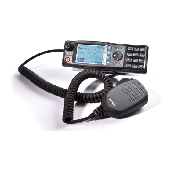
Page 9: List Of Figures
LIST OF FIGURES Figure 1: SDM630 Control Head. Figure 2: Main/Default screen (example). Figure 3: Icon Locations. Figure 4: Menu Navigation. Figure 5: Channel Screen. Figure 6: Zone Menu. Figure 7: Setup Menu. Figure 8: User Options Menu. Figure 9: Mute Adjust Screen. Figure 10: Contact Menu screen. - Page 10 LIST OF TABLES Table 1: Rated Power and Recommended Lateral Distance for General Population Uncontrolled Exposure for SDM600AC (150 MHz to 174 MHz). Table 2: Rated Power and Recommended Lateral Distance for Occu- pational/Controlled Exposure for SDM600AC (150 MHz to 174 MHz). Table 3: Rated Power and Recommended Lateral Distance for General Population Uncontrolled Exposure for SDM600TU and SDM600UW (406.1 MHz to 512 MHz).
-
Page 11: Personal Safety
PERSONAL SAFETY SAFETY PRECAUTIONS These Safety Precautions, Warnings and Cautions advise personnel of specific hazards which may be encountered when using this equipment and that control measures may be required to prevent injury to personnel, and damage to equipment and/or the environment. -
Page 12: Warnings
WARNINGS RADIO FREQUENCY RADIATION WARNING RADIO FREQUENCY RADIATION. A RADIO FREQUENCY (RF) RADIATION HAZARD EXISTS IN THIS EQUIPMENT. TO AVOID RF INJURY, DO NOT TOUCH THE ANTENNA WHEN THE TRANSMITTER IS IN USE. DO NOT OPERATE TRANSMITTER WITH ANTENNA DISCONNECTED. ... -
Page 13: Compliance With Rf Energy Exposure Guidelines (United States And Canada)
RF ENERGY EXPOSURE AWARENESS AND CONTROL INFORMATION AND OPERATIONAL INSTRUCTIONS FOR FCC OCCUPATIONAL USE REQUIREMENTS Before using your Simoco mobile two-way radio, read this important RF energy awareness and control information and operational instructions to ensure compliance with the Federal Communications Commission’s (FCCs) RF exposure guidelines. -
Page 14: Federal Communications Commission Regulations
RF exposure and to satisfy compliance regulations. Compliance with RF Exposure Standards Simoco two-way radios are designed and tested to comply with a number of national and international standards and guidelines (listed below) for human exposure to RF electromagnetic energy. -
Page 15: Instructions
• Do not use this device if the operational requirements described herein are not met. Instructions: • Transmit no more than the rated duty factor of 50% of the time. To transmit (talk), push the Push-To-Talk (PTT) button. To receive calls (listen), release the PTT button. -
Page 16: Vehicle Installation Instructions
Vehicle Installation Instructions The antenna(s) used for the SDM600 series of mobile two-way radios must be installed to provide a separation distance of at least 90 cm (35.5 inches) from all persons for SDM600AC (150 MHz -174 MHz), 75 cm (29.5 inches) for SDM600TU and SDM600UW (406.1 MHz –... -
Page 17: Approved Accessories
FCC regulations. Approved Accessories • This radio meets the FCC RF exposure guidelines when used with the Simoco accessories supplied or designated for the product. Use of other accessories may not ensure compliance with the FCCs RF exposure guidelines and may violate FCC regulations. -
Page 18: General Notes
GENERAL NOTES MANUAL COMPILATION This manual provides detailed information on the use of the SDM630 Mobile Radio Transceiver including Introduction, Controls, Basic Operations, Main Screen, Menu System, Menu Screens, Special Functions, Troubleshooting and Options. Details of both “basic” and “optional units” have been included in this User Manual, therefore, some material may not be relevant to every system. -
Page 19: Simoco Support
Email:customer.service@simocowirelesssolutions.com Technical Support In order to streamline support requests and better serve our customers, at Simoco Wireless Solutions we utilize a support ticket system. Every support request is assigned a unique ticket number, which customers can use to track the progress and responses online. - Page 20 A link to the online Simoco Wireless Solutions Support Centre Ticket Tracking system is provided www.simocowirelesssolutions.com/support If you still require further technical assistance after raising a support ticket, please contact us via the email addresses or via the Technical Support Helpline numbers below.
-
Page 21: Abbreviations
PABX Private Automatic Branch Exchange PSTN Public Switched Telephone Network Push (Press) To Talk Radio Frequency RSSI Received Signal Strength Indicator Receiver Simoco Digital Mobile SMSG Short Message TGID Talk Group Identification Transmitter TXTMSG Text Message Unit Identification United States Doc Number: TNM--U-E-0108 ISSUE 1.5... -
Page 22: Glossary Of Terms
GLOSSARY OF TERMS The table below contains a list of the common terms used through out this document and their meanings. Term Meaning ‘……’ Reference to a setting or feature (exactly as it is displayed) that may be selected or enabled either directly or through a software application, e.g. ‘Menu’, ‘Control’, ‘Switch’. -
Page 23: Introduction
1.1. OVERVIEW The SDM600 Series Radios are versatile Digital Signal Processor (DSP) controlled, two- way mobile radios. The SDM600 Series is available in a number of frequency bands and versions for specific applications. These Operating Instructions describe the operation of the DMR Tier II Standard compliant Mobile Radio, consisting of an SDM600 Transceiver and SDM630 Control Head. -
Page 24: Controls
2 CONTROLS The SDM630 Control Head has the following features: • 11 programmable direct Function Buttons. • 10 additional indirect Function Buttons (keys 0 – 9). • 2000 Channels. • 40 Zones. • 250 Channels per zone. • Liquid Crystal Display (LCD) 102 x 64 graphic display. Eight lines of 14 characters (small font). -
Page 25: Table 5: Sdm630 - Control Functions
SDM630 Key Label Function Programmable Function key. Function Key F2 Default – Channel Up. Programmable Function key. Function Key F3 Default – Channel Down. Programmable Function key. Function Key F4 Default – Monitor Toggle. Programmable Function key. Function Key F5 Default –... -
Page 26: Main Screen
3 MAIN SCREEN 3.1. LAYOUT An example of the main or default screen that is displayed when the radio is switched on is shown below in Figure 2. Figure 2: Main/Default screen (example). The screen has three main areas: the Icon Area; the Text Panel; and the Soft Labels area. -
Page 27: Icons
3.1.3. Icons The lower part of the display is reserved for Standard and Special Icons. There are only six positions for icons to be displayed (see Figure 3 ), however, the number of icons that can be displayed exceed this. Therefore, some icons will share the same location (see Table 6). -
Page 28: Table 6: Icon Locations Table
Position Icons Locked Keypad Individual Call Table 6: Icon Locations Table. Details of the Icons that can be displayed are contained below in Table 7. ICON INDICATION A filled speaker icon indicates that a signal is present and the radio is unmuted. The outline speaker icon indicates that a signal is present and the radio is muted. -
Page 29: Table 7: Icon Details
ICON INDICATION Connecting icon. Shown when a text message is being sent and the connection is in progress. Connection Fail icon. Shown when a text message transmission has failed. The asterisk symbol indicates whether the radio has been “called” or is in the “on-call”... -
Page 30: Basic Operations
4 BASIC OPERATIONS 4.1. TURNING THE RADIO ON AND OFF On the SDM630, the On/Off power switch is part of the rotary volume control knob, located on the top left hand side of the radio control head. To turn the radio on, press and hold the volume knob until a beep is heard. The radio will turn on after about 1 second. -
Page 31: Selecting A Channel
a. From the main default screen, a zone can quickly be selected by pressing the ‘Zone Up’ or ‘Zone Down’ function keys when these have been programmed. 4.4. SELECTING A CHANNEL The radio can have up to 2000 channels in its channel database. A channel can be selected as follows: 1. -
Page 32: Receiving A Call
Call Icons Icon shown when transmitting a private call. Icon shown When transmitting a group call. Icon shown When receiving an individual emergency call Table 8: Private & group Call Icons. A call can be made as follows: 1. Through the Contact or Call Log menus: a. -
Page 33: Sending A Message
If the caller UID of a newly received unanswered call is already in the Call Log list, the old Call Log record of that UID will be replaced by the new record and added to the top of the list. ... -
Page 34: Scan Functions
During Tx, the radio will generate an emergency broadcast call on either the currently selected channel or an FPP nominated channel. Others may listen to the automatic transmissions to hear conversations near the radio. Turning the radio off and on will disable emergency mode. 4.9. -
Page 35: Keypad Lock
key. Once a channel is “skipped” it will not be scanned for the duration that Zone/Channel selection. When transmitting on a channel, the second line of the display shows the name of the current channel that the radio is transmitting on. ... -
Page 36: Menu System
5 MENU SYSTEM This section details the operation of the menu system for the SDM630. The SDM630 has a menu system that is configurable by the FPP. The FPP has a pool of menu entries that can be applied as required in the order required. In simple configurations, no menu can be programmed, if required. -
Page 37: Menu Navigation
5.1. MENU NAVIGATION Pressing the ‘F4’ key selects Menu mode from the main Channel Screen. Once in menu mode, the ▼ and ▲ keys cycle through the menus. To exit Menu mode, press the ‘F4’ key again or the Menu timeout will exit automatically. -
Page 38: Menu Screens
6 MENU SCREENS The menu structure on the SDM630 is configurable using the FPP. A system administrator usually tailors the order and presence of the menu options to specific customer requirements. This section describes all the menus that are currently available. ... -
Page 39: Zone Menu
6.2. ZONE MENU The Zone menu allows the user to change Zones. A Zone is normally defined as a group of radio channels with a common operational role. Figure 6: Zone Menu. Use the ▼ and ▲ keys to choose the required Zone. Press the ‘S’ key to select the required Zone. -
Page 40: User Options Menu
• RSSI (Received Signal Strength Indication); • Test Mode; • Mute Adjust; • Help; or • User Options. 6.4. USER OPTIONS MENU The User Options menu allows the user access to a preset selection of menu options for user radio interface configuration items. These include the backlight timeout period, the backlight brightness, the display contrast, speaker and alert tone volume control limitations, and the key beeps function. -
Page 41: Contact Menu
The SDM600 series radios have a carrier noise mute and it is recommended that a default mute setting of 4 is used. This means that, with a setting of 4, the mute will open at the point where an analogue signal is sufficiently noise free to be intelligible. -
Page 42: Radio Information
Use the ▼ and ▲ keys to scroll through the available contacts. Pressing the ‘S’ key will display the details for the selected contact (see Figure 11 below). Pressing the PTT key will place a call to the selected contact. ... -
Page 43: Rssi Menu
Figure 13: Radio Info screens. 6.8. RSSI MENU The RSSI menu displays the signal strength of the received RF signal. The current display is in dBm re 50 Ω and 1 mW, and the reading is typically accurate to within ±2 dBm. -
Page 44: Call Log
A lower RSSI number indicates a stronger signal, i.e. –80 dBm is a stronger signal than –100 dBm. 6.9. CALL LOG The Call Log menu displays the list of received individual call records for the radio. The most recently received call record is displayed at the top of the list. ... -
Page 45: Inbox
Figure 17: Messages Menu. Received messages are stored in the ‘INBOX’. Transmitted messages are stored in the ‘OUTBOX’. Both can be viewed and deleted as required. If there are unread messages stored in the radio, the envelope icon will be displayed on the default screen. -
Page 46: Outbox
6.10.2. Outbox The Outbox is used to store the transmitted (sent) messages. Up to 20 messages can be stored in the outbox. These are volatile messages, which means on radio start-up, the outbox will be empty. Figure 19: Messages Outbox. ... -
Page 47: New Messages
To select a different Status message, use the▼ and ▲ keys to scroll through the programmed status messages. Each Status message will be displayed in turn. Press the ‘B’ key to return to the previous screen. Press the ‘S’ key to display the Send screen, which allows you to select a Contact from the Contacts menu. -
Page 48: Sending Status, Template And Text Messages
Each message can be up to 160 characters in length. The number of remaining characters that can be entered is displayed above the message. Text characters are entered using the keypad. Each keypad button is labelled with up to 4 text characters (e.g. -
Page 49: Viewing Received Messages
Figure 23: Send message screen. Sending a message can fail if the destination radio is not available. 6.10.6. Viewing Received Messages When selected, the details of received messages (status, template and text messages) stored in the Inbox will be displayed on the Messages View screen. ... -
Page 50: Scan Menu
The message options are: • REPLY: This will open a text Message screen in order to reply to the selected message. • DELETE: This will delete the received message. • BACK: This will return to the message inbox. The ‘DELETE’... -
Page 51: Alert Volume Menu
Use the ▼ and ▲ keys to choose the required contrast level. Press the ‘S’ key to save the selected contrast level and return to the previous screen. 6.13. ALERT VOLUME MENU This menu allows the user to set the offset of the Alert Volume in relation to the current Volume setting. -
Page 52: Key Beeps
Figure 29: Speaker Volume Menu. Use the ▼ and ▲ keys to select the relative speaker volume level. A beep will sound at the indicated level each time the setting is changed. To accept and save the setting and return to the previous screen, press the ‘S’ key. 6.15. -
Page 53: Brightness Menu
When the Backlight is enabled, the control screen will be illuminated whenever there is any user activity. The backlight will remain on with no further user activity for the set period, after which, the backlight will turn off. The maximum backlight timeout period is programmed by the FPP. The numerical values on the display are in seconds. -
Page 54: To Setup A Diversion
The top part of the screen shows if any diversion are in place, while the lower part of the screen provides the divert options. Use the ▼ and ▲ keys to select the required divert option. Pressing the ‘S’ key will initiate the diversion setup. -
Page 55: To Cancel A Diversion
Press the ‘S’ key to complete the un-divert procedure. 6.19. GPS The SDM600 Series Mobile Radio transceiver can be fitted with a GPS Option Board kit. If required, this GPS receiver can then be activated to provide unit location data to another radio system entity. -
Page 56: Missed Calls
Figure 38: GPS screen. The menu provides ‘Off’ and ‘On’ options, and these will only operate if the radio has been configured by the FPP to have GPS Reporting Enabled. 6.20. MISSED CALLS The Missed Calls menu displays the list of those individual call records that have been received but not answered for the radio. -
Page 57: Talk Groups
Pressing the PTT key will place a call to the selected contact. To return to the previous Menu level, press the ‘B’ key. 6.21. 6.21 TALK GROUPS The Talk Groups menu allows the user to select the Talk Group. ... -
Page 58: Figure 43: Test Mode Menu
Figure 43: Test Mode Menu. When programmed into a radio and then selected, the Test Mode menu simply lists the test modes that are available for use on the radio. Use the ▼ and ▲ keys to select the required test. Press the ‘S’ key initiate the test. Doc Number: TNM--U-E-0108 ISSUE 1.5 Page... -
Page 59: Special Functions
7 SPECIAL FUNCTIONS Special functions can be programmed to each of the keys/buttons on the SDM630 Control Head by the FPP. These special functions can be simple short cuts to specific menus or an on/off toggle facility for specific actions. 7.1. -
Page 60: Menu
7.8. MENU The Menu function key is used for accessing the menu system. 7.9. ZONE, CHANNEL, CONTACT AND MUTE These are specific functions that provide direct access to the ‘Channel’, ‘Zone’, ‘Contact’ and ‘Mute Adjust’ menus. 7.10. RESET The Reset function is usually assigned to the F6 key, and is used as a cancel function when in a menu or as a backspace when entering keypad dial-strings. -
Page 61: Troubleshooting
• That all cables and their connections are secure; and • The vehicle battery is charged. If these checks are OK, please see Simoco Wireless Solutions Support page and contact the relevant Technical Support Helpline or Customer Services for further advice. Doc Number: TNM--U-E-0108 ISSUE 1.5... -
Page 62: Options And Accessories
9 OPTIONS AND ACCESSORIES The options and accessories that are available for the SDM600 Mobile Radio are listed below in Table 10. Contact Simoco Wireless Solutions for further information. Part No. Description Notes MA-LOUDSPKR Loudspeaker, Slimline 75 x 90 mm... -
Page 63: Appendix A: Alert Tones And Messages
Appendix A: ALERT TONES AND MESSAGES ALERT TONES The Alert Tones supported by the SDM600 Series Mobile Radio are listed below in Table 11. Frequency, Tone Duration, Tone Description Repeats Key Beep 940 Hz 60 ms Generated by key presses. Key Beeps can be enabled or disabled in the FPP. - Page 64 This page has been intentionally left blank.
- Page 65 Simoco Wireless Solutions Field House, Uttoxeter Old Road, Derby. DE1 1NH. Tel: +44 (0) 1332 375500 Fax: +44 (0) 1332 375501 www.simocowirelesssolutions.com...
Need help?
Do you have a question about the SDM600 Series and is the answer not in the manual?
Questions and answers