Table of Contents
Advertisement
Quick Links
P25 SRM9022 MOBILE RADIO
CONVENTIONAL/TRUNKING OPERATING INSTRUCTIONS
ISSUE 4.0
Document Number: TNM-U-E-0055
Unrestricted
Date: December 2019
© Simoco Wireless Solutions 2019
Simoco Wireless Solutions
Uttoxeter Old Road,
Tel: +44 (0) 1332 375500
Fax: +44 (0) 1332 375501
www.simocowirelesssolutions.com
Field House,
Derby.
DE1 1NH.
Simoco Wireless Solutions
1270 Ferntree Gully Road,
Scoresby Victoria,
3179
Australia.
Tel: +61 (0)3 9730 3999
Fax: +61 (0)3 9730 3988
www.simocowirelesssolutions.com
Advertisement
Table of Contents

Related Manuals for Simoco P25 SRM9022


Summary of Contents for Simoco P25 SRM9022
- Page 1 P25 SRM9022 MOBILE RADIO CONVENTIONAL/TRUNKING OPERATING INSTRUCTIONS ISSUE 4.0 Document Number: TNM-U-E-0055 Unrestricted Date: December 2019 © Simoco Wireless Solutions 2019 ...
- Page 2 This page has been intentionally left blank. Doc Number: TNM-U-E-0055 ISSUE 4.0 Page...
-
Page 3: Preface
Whilst every endeavour has been made to eliminate any errors, some may still exist. It is requested that any errors or omissions noted should be reported to either of the following who are part of the Simoco group: Doc Number: TNM-U-E-0055 ISSUE 4.0... -
Page 4: Document History
To order printed copies of this or any of the above publications, please contact Simoco. See the Support page for contact information. A comprehensive list of documentation is available for download on the Simoco website www.simocowirelesssolutions.com via the Partner Portal. -
Page 5: Table Of Contents
MANUAL COMPILATION CONVENTIONS PAGINATION SIMOCO SUPPORT ABBREVIATIONS GLOSSARY OF TERMS 1 INTRODUCTION 1.1. CONFIGURATION 1.2. MODES OF P25 SRM9022 OPERATION 2 CONTROLS 3 MAIN SCREEN 3.1. LAYOUT 3.1.1. Soft Labels 3.1.2. Text Panel 3.1.3. Icons 4 MENU SYSTEM 4.1. MENU NAVIGATION 5 MENU SCREENS 5.1. - Page 6 5.6. PHONEBOOK EDIT MENU 5.6.1. Phonebook Edit – To Delete an Entry 5.6.2. Phonebook Edit – To Add a New Entry 5.6.3. Phonebook Edit – To Edit an Existing Entry 5.7. SETUP MENU 5.8. USER OPTIONS MENU 5.9. CONTRAST MENU 5.10.
- Page 7 7.9. MODE 7.10. MUTE 7.11. RESET 7.12. SCAN 7.13. SCAN EDIT 7.14. SCRAMBLER (P25 ANALOGUE) 7.15. SKIP 7.16. SQUELCH (P25 CONVENTIONAL) 7.17. TALK AROUND 7.18. ZONE 7.19. UNDEFINED Appendix A: ALERT TONES AND MESSAGES ALERT TONES Appendix B: COMPLIANCE WITH RF ENERGY EXPOSURE GUIDELINES (UNITED STATES AND CANADA) RF ENERGY EXPOSURE AWARENESS AND CONTROL INFORMATION AND OPERATIONAL INSTRUCTIONS FOR FCC OCCUPATIONAL USE REQUIREMENTS...
-
Page 8: List Of Figures
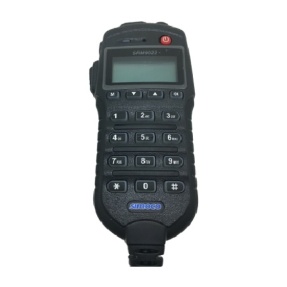
LIST OF FIGURES Figure 1: SRM9022 Controller Microphone. Figure 2: Main/Default screen. Figure 3: Icon Locations. Figure 4: Menu Navigation. Figure 5: Alert Tones. Doc Number: TNM-U-E-0055 ISSUE 4.0 Page... - Page 9 LIST OF TABLES Table 1: SRM9022 – Control Functions. Table 2: LED function. Table 3: Icon Details. Table 4: Rated Power and Recommended Lateral Distance for General Population Uncontrolled Exposure for SDM600AC (150 MHz to 174 MHz). Table 5: Rated Power and Recommended Lateral Distance for Occu- pational/Controlled Exposure for SDM600AC (150 MHz to 174 MHz).
-
Page 10: Personal Safety
PERSONAL SAFETY SAFETY PRECAUTIONS These Safety Precautions, Warnings and Cautions advise personnel of specific hazards which may be encountered during the procedures contained in this document and that control measures may be required to prevent injury to personnel, and damage to equipment and/or the environment. - Page 11 DATED 29 APRIL 2004. DANGEROUS VOLTAGES Dangerous voltages may exist in this equipment, for the appropriate Safety precautions, refer to the relevant Electrical Safety Regulations appropriate to the country of operation. HUMAN EXPOSURE TO RADIO FREQUENCY RADIATION (FCC) WARNING TO COMPLY WITH THE MAXIMUM PERMISSIBLE EXPOSURE (MPE) LIMITS REFERENCED IN 47 CFR 1.1310 TABLE 1, THE FOLLOWING MINIMUM SAFE OPERATING DISTANCES MUST BE OBSERVED: 150 MHz to 174 MHz: 1.8 m...
-
Page 12: Waste Electrical And Electronic Equipment (Weee) Notice
WASTE ELECTRICAL AND ELECTRONIC EQUIPMENT (WEEE) NOTICE The Waste Electrical and Electronic Equipment (WEEE) Directive became law in most EU countries during 2005. The directive applies to the disposal of waste electrical and electronic equipment within the member states of the European Union. ... -
Page 13: General Notes
GENERAL NOTES MANUAL COMPILATION This manual provides information on using the SRM9022 P25 Mobile Radio. Details of both ‘basic’ and ‘optional units’ have been included in this User Manual, therefore, some material may not be relevant to every system. Configuration is dependent upon the specification by the customer when the equipment was ordered and installed. -
Page 14: Simoco Support
Email:customer.service@simocowirelesssolutions.com Technical Support In order to streamline support requests and better serve our customers, at Simoco we utilize a support ticket system. Every support request is assigned a unique ticket number, which customers can use to track the progress and responses online. For reference, Simoco provide complete archives and history of all customer support requests. - Page 15 A link to the online Simoco Group Support Centre Ticket Tracking system is provided www.simocowirelesssolutions.com/support If you still require further technical assistance after raising a support ticket, please contact us via the email addresses or via the Technical Support Helpline numbers below.
-
Page 16: Abbreviations
ABBREVIATIONS Acknowledgement Advanced Encryption Standard Automated Teller Machine Bit Error Rate Command Line Interface Cyclic Redundancy Check Clear To Send decibel relative to the carrier decibel relative to the isotropic decibel relative to the milliwat Data Communication Equipment Doc Number: TNM-U-E-0055 ISSUE 4.0 Page... - Page 17 DHCP Dynamic Host Configuration Protocol Domain Name Server Data Terminal Equipment Electro-Magnetic Compatibility Federal Communications Commission Forward Error Correction Front End Processor General Public License HTTPS Hypertext Transfer Protocol Secure Internet Protocol Doc Number: TNM-U-E-0055 ISSUE 4.0 Page...
- Page 18 kbps kilobit per second Local Area Network Line-of-Sight Media Access Control MDIX Medium Dependant Interface Crossover Management Information Base Maximum Recption Unit Maximum Transmission Unit Normally Closed Network Management System Normally Open Network Time Protocol Doc Number: TNM-U-E-0055 ISSUE 4.0 Page...
- Page 19 Operating System Personal Computer Packet Error Rate Point Of Sale Power Radio Frequency RoHS Restriction of the use of Hazardeous Substances Repeater Received Signal Strength Request To Send REmote Terminal Unit Receiver Doc Number: TNM-U-E-0055 ISSUE 4.0 Page...
- Page 20 SCADA Supervisory Control and Data Acquisition SNMP Simple Network Management Protocol Software Defined Radio Transmission Control Protocol Terminal Server 5 Transmitter User Datagram Protocol VSWR Voltage Standing Wave Ratio WEEE Waste Electrical and Electronic Equipment Radio IP Exchanger Doc Number: TNM-U-E-0055 ISSUE 4.0 Page...
-
Page 21: Glossary Of Terms
GLOSSARY OF TERMS Term Meaning Bank See Zone. Channel A logical combination of: Network Access Code (NAC); Radio Frequency; Default Talk Group Identity (TGID); Encryption Key Index (KID); and other channel associated parameters (CTCSS, Scan etc). DTMF Dual Tone Multi-Frequency signalling. Used to dial into Telephone networks using tone dialling. -
Page 22: Introduction
1.1. CONFIGURATION Before you can use the P25 SRM9022 Radio, it must be configured using the P25 FPP. The configuration process defines and loads the radio channels, signalling and user options/settings so that the radio will operate with your system. -
Page 23: Controls
2 CONTROLS The SRM9022 Controller Microphone has the following features: • 6 programmable direct Function Buttons. • 10 additional indirect Function Buttons (keys 0 – 9). • 1500 Channels. • 40 Zones. • 250 Channels per zone. • Liquid Crystal Display (LCD) 102 x 64 graphic display. Eight lines of 14 characters (small font). -
Page 24: Table 1: Srm9022 - Control Functions
SRM9022 Key Label Function This pushbutton turns the radio on and off. To turn the radio on, press and hold the button Power On/Off until the radio turns on. To turn the radio off, press and hold the button for 2 secs until the radio turns off. -
Page 25: Main Screen
3 MAIN SCREEN 3.1. LAYOUT An example of the main or default screen that is displayed when the radio is switched on is shown below in Figure 2. Figure 2: Main/Default screen. The screen has three main areas: the Icon Area; the Text Panel; and the Soft Labels area. -
Page 26: Icons
ii. The Zone Name shows the text associated with the currently selected radio zone. 2. Non-persistent Text messages, e.g. keypad dial string entries, received status/data messages, error messages, etc. 3.1.3. Icons The lower part of the display is reserved for Standard and Special Icons. There are only six positions for icons to be displayed (see Figure 3), however, the number of icons that can be displayed exceed this. -
Page 27: Table 3: Icon Details
ICON INDICATION Received Signal Strength Indication (RSSI). A stronger signal will display more bars above the “antenna” icon. Encryption Indicator. The icon is shown when the selected channel is programmed for encryption. If an unencrypted signal is received, the icon will not be displayed. -
Page 28: Menu System
4 MENU SYSTEM This section details the operation of the menu system for the SRM9022. The SRM9022 has a menu system that is configurable by the FPP. The FPP has a pool of menu entries that can be applied as required in the order required. In simple configurations, no menu can be programmed, if required. -
Page 29: Menu Navigation
4.1. MENU NAVIGATION Pressing the ‘M’ key selects Menu mode from the main Channel Screen. Once in menu mode, the ▼ and ▲ keys cycle through the menus. To exit Menu mode, press the ‘M’ key again or the Menu timeout will exit automatically. -
Page 30: Menu Screens
5 MENU SCREENS The menu structure on the SRM9022 is configurable using the FPP. A system administrator usually tailors the order and presence of the menu options to specific customer requirements. This section describes all the menus that are currently available. It also describes the Channel Screen, which is the main default screen that is displayed after the radio is switched on. -
Page 31: Zone Menu
If a radio channel is defined as a P25 Conventional Digital Channel, it will only receive P25 digital signals. If a radio channel is defined as an Analogue FM channel, it will receive both P25 Digital* and Analogue FM signals. ... -
Page 32: Squelch Menu
5.3. SQUELCH MENU The Squelch menu allows the channel’s default squelch mode to be modified. If the selected channel is changed or the radio is switched off, the channel’s default squelch setting will be restored. From the main channel screen, press the ‘M’ key to enter Menu Mode. Use the ▼ /▲ keys to scroll through menu options. -
Page 33: Digital Operation
For an analogue channel, the ▼ /▲ keys can be used to select either Monitor or Normal squelch mode. For each channel type, after selecting the required squelch mode, press the OK key to confirm the selection and return to the default channel screen. ... - Page 34 With the Mute Adjust menu option displayed, press the OK key to access the Mute Adjust screen. A numeric value of the present mute level will be displayed. Use the ▼ /▲ keys to adjust the mute threshold as required. Press the OK key confirm the selected mute setting and return to the default channel screen.
-
Page 35: Phonebook Menu
5.5. PHONEBOOK MENU From the main channel screen, press the ‘M’ key to enter Menu Mode. Use the ▼ /▲ keys to scroll through menu options. With the PhoneBook menu option displayed, press the OK key to access the PhoneBook screen. ... -
Page 36: Making An Individual Call With Call Alert
• The radio will return to the default channel screen. 5.5.2. Making an Individual Call with Call Alert From the PhoneBook Screen, with the required phonebook entry displayed, when the OK key is pressed: • A Call Alert is sent to the displayed ID. •... -
Page 37: Phonebook Edit - To Delete An Entry
The pop-up menu items are: • Add. Used to add a new phonebook entry. • Edit. Used to edit (modify) the selected phonebook entry. • Delete. Used to delete the currently selected phonebook entry. Note:-The operations of adding a new phonebook entry and editing an existing entry are very similar and carried out in several steps to ensure that all the required details are entered correctly. -
Page 38: Phonebook Edit - To Edit An Existing Entry
There are six possible types of Phonebook entries. These are: Conv.Unit ID (Option 0) Conv.PSTN (Option 1) Conv.Group (Option 2) Trunk Unit ID (Option 3) Trunk PSTN (Option 1) Trunk Group (Option 4) Using the keypad, make the required selection (0 – 4) and select OK. ... - Page 39 The System ID entry can then be changed using the numeric digits and ▼ key as a destructive backspace. If the System ID has to be changed, use the keypad and the ▼ key to enter the new System ID as required and then press the OK key. ...
- Page 40 The Unit ID can then be changed using the numeric digits and ▼ key as a destructive backspace. If the Unit ID has to be changed, use the keypad and the ▼ /▲ keys to enter the new Unit ID as required and then press the OK key. ...
-
Page 41: Setup Menu
5.6.3.5. Name Upon entering the Edit Name screen, the current Name of the selected phonebook entry is displayed. The name entry can be changed using the numeric digits and the ▼ /▲ keys to move the cursor with the Reset function key to delete. ... -
Page 42: User Options Menu
Use the ▼ /▲ keys to scroll through and select the required Setup sub-menu. The Setup menu structure may include, for example: • User Options; • Contrast; • Alert Volume; • Crypto Key (Select Transmit Encryption Key); • Radio Info (Radio software and hardware information); •... -
Page 43: Contrast Menu
Pressing the Back or ‘M’ key saves all the function settings and returns to the next highest menu level. 5.9. CONTRAST MENU The Contrast menu allows the screen’s contrast setting to be altered. From the Setup menu, use the ▼ /▲ keys to scroll through sub-menus and, with the Contrast menu option displayed, press the OK key to access the Contrast adjustment screen. -
Page 44: Radio Info Menu
From the Setup menu, use the ▼ /▲ keys to scroll through sub-menus and, with the Alert Volume menu option displayed, press the OK key to access the Alert Volume adjustment screen. Use the ▼ /▲ keys to adjust the alert volume numeric setting as required. A beep will sound at the indicated level each time the setting is changed. - Page 45 P25 Conv. ID and Radio Band Radio SW Ver. & Serial No. Application Upgrade Ver., Date & PLA Application SW Ver. & Date Code P25 Radio Unit Trunked ID and IP Addr. P25 Trunked SysID, WACN, GID and UID Feature Authorisation Enables Encryption Status Doc Number: TNM-U-E-0055 ISSUE 4.0...
-
Page 46: Mode Menu
External Application Memory Status The ‘Radio Info’ screens are read-only screens. Press OK to return to the Channel Screen. 5.12. MODE MENU The Mode menu is used for changing from one radio to another, such as Private Mobile Radio/Land Mobile Radio (PMR/LMR) mode to P25 or MPT1327 trunking. ... -
Page 47: Rssi Menu
Keypad shortcuts can be used to change modes from the keypad as follows: • PMR (*60#). • P25 (*80#). • MPT Network 1 (*71#). • MPT Network 2 (*72#). 5.13. RSSI MENU The RSSI screen displays the received signal strength in dBm. When the radio has been correctly calibrated, the reading is typically accurate to within ±2 dBm between the range of −120 dBm and −80 dBm. -
Page 48: Crypto Key Menu
5.14. CRYPTO KEY MENU The Crypto Key menu allows the digital channel’s default transmit encryption key to be modified. On an encrypted radio channel, the radio will attempt to use any of the stored encryption keys to decrypt received signals. ... -
Page 49: Stored Calls Menu
5.15. STORED CALLS MENU The Stored Calls menu is used to display the records of individual calls received. When the Stored Calls screen is accessed, the record of the most recently received call is displayed. OK key to save the changes and return to the main channel screen. ... -
Page 50: To Call Back A Stored Call
With the Stored Calls screen displayed, press the ‘M’ or Back key to return to next highest menu screen. Press the ‘Reset’ function key (if configured) to return to the default screen. 5.15.1. To Call Back a Stored Call From the Stored Calls screen, use the ▼ /▲ keys to scroll through and select the required stored call record from the list. -
Page 51: Messages - Pop-Up Menu
To view, send or delete messages, from the main channel screen, press the ‘M’ key to enter Menu Mode. Use the ▼ /▲ keys to scroll through the menu options. With the ‘Messages’ menu option displayed, press the OK key to access the Messages screen. ... -
Page 52: Messages View Screen
Press the ‘M’ or Back keys to return to the next highest menu screen. 5.16.2. Messages View Screen Received messages (both short messages and text messages) can be viewed from the ‘Messages View’ screen. When this screen is displayed it will show the most recently received message. ... - Page 53 5.16.2.1. Messages View – Pop-Up Menu The Messages View pop-up menu selections are: • DELETE – to delete the currently selected message. • MORE – to view the full (entire) message. • REPLY – to select the method of replying to the selected message. ...
- Page 54 5.16.2.3. Messages Reply – Pop-Up Menu The Messages Reply pop-up menu selections are: • CALL – to call the selected sender. • SMSG – to send a short message to the sender. • TXTMSG – to edit and send a text message to the sender. ...
- Page 55 Use the ▼ /▲ keys to scroll through and select the required short message to be sent from the pre-programmed list. Press the OK key to send the selected short message in reply to the received message. The radio will then return to the default screen. ...
-
Page 56: Send Message (Short Or Text)
Press the ‘Reset’ function key (if configured) to return to the default screen without sending a text message reply. 5.16.3. Send Message (Short or Text) This menu is used to send either a short message or a text message to another party. ... - Page 57 Use the ▼ /▲ keys to select the require option. With ‘CANCEL’ selected, press the OK key to return to the previous screen, i.e. Short Message Screen, or Edit Text Message Screen. With ‘PH.BK’ selected, press the OK key to display the ‘Phone Entry’ selection screen. ...
-
Page 58: Scan Edit Menu
The entered digits can be deleted by using the ▼ key. Press the ‘M’ or Back key to return to the Destination Selection pop-up menu screen. Press the ‘Reset’ function key (if configured) to return to the default screen display. ... - Page 59 The second line from the top shows the name of the selected channel in the scan group. The next line shows the channel type, i.e. ‘Member’ if it is a normal member of the scan group, ‘Priority’ if it is the priority channel, or ‘Skipped’ if the channel is currently skipped from the scan group.
-
Page 60: Scan Group Add Screen
The priority level of the channel to add to the scan group is selected from this screen. The options are: • Member. A member channel is a normal channel with lowest priority in the scan group. • Prty1. A Priority 1 channel will have the highest priority in the scan group. •... -
Page 61: Menu
5.18. NO MENU The ‘No Menu’ option exists in the FPP for when a menu entry is not required. If all entries are ‘No Menu’, there will be no menu system available. This may be desirable for simple configurations. Doc Number: TNM-U-E-0055 ISSUE 4.0 Page... -
Page 62: Common Functions And Facilities
6 COMMON FUNCTIONS AND FACILITIES 6.1. SWITCH ON/SWITCH OFF The On/Off power switch on the SRM9022 is a red push-button located on the top right-hand side of the radio controller microphone. To turn the mobile on, press and hold the button down until a beep is heard. The radio will turn on after about one second. -
Page 63: Volume Adjustment
6.3. VOLUME ADJUSTMENT The Volume Control adjusts the speech level at the radio speaker. The volume is adjusted by the Volume Up and Volume Down buttons on the top of the SRM9022 Controller Microphone. Note:- The radio may be programmed so that the volume cannot be completely turned off. -
Page 64: Received Individual Calls
6.5. RECEIVED INDIVIDUAL CALLS Unanswered received individual calls addressed to the radio are stored in radio memory. The caller unit ID may be viewed, answered and deleted by the user as desired. A newly received individual call addressed to the radio sounds an alert tone periodically until the user presses any key. -
Page 65: Scan/Vote Functions
In most systems it is important to wait a short time between pressing the PTT and commencing to speak. This ensures that the path is properly established and avoids lost, truncated or distorted speech. While transmitting, the vertical bars on the left hand side will indicate the transmit power level programmed for that channel. -
Page 66: Scan/Vote Screen
6.7.1. Scan/Vote Screen A Scan can be started by: • Pressing the function key that has been assigned the scan function by the FPP; or • Selecting a zone channel that has been assigned to automatically scan by the FPP; •... -
Page 67: Keypad Lock
6.8. KEYPAD LOCK The radio has a Keypad Lock function that prevents accidental key presses. The SRM9022 Controller Microphone keypad lock function may be enabled by the FPP during configuration. If this function is activated, a key lock icon will be displayed in the bottom right-hand side of the display when the keypad is locked. -
Page 68: Making An Emergency Call
6.10.2. Making an Emergency Call When the emergency key is pressed and held for a specific time (determined by the FPP), the radio will change to emergency mode. Under emergency mode, the radio can operate in three FPP configurable modes: ... -
Page 69: Special Function Keys
This section lists Functions that may be programmed to the programmable function keys. Consult Simoco for those functions that have been programmed in to your radio. 7.1. ALARM The Alarm function key is used to put the radio into Emergency Mode. -
Page 70: Crypto
If the Talk Around function is enabled and selected, then Talk Around will be cancelled when the channel is changed. 7.4. CRYPTO The Crypto function provides a shortcut to the Encryption select menu for user selection of the current encryption key. 7.5. -
Page 71: Menu
This function is unaffected by channel change. 7.8. MENU The Menu function key is used for accessing the menu system and selects the first main menu entry. This is normally assigned to the F1 key, labelled ‘M’. 7.9. MODE This function is a short cut to the Mode menu. The Mode menu is used to change radio modes, e.g. -
Page 72: Scan Edit
Scan is supported in both analogue and digital mode. If scan is enabled for the current channel in the current zone and auto scan is not enabled, then start scanning the channels defined in the current channel’s scan group. The second press of the scan key will turn scanning off. -
Page 73: Talk Around
7.17. TALK AROUND This function will change the Transmit and Receive frequencies (and CTCSS tones) so that a local Repeater can be bypassed. It is supported in both analogue and digital mode. The first button press will redefine the channel’s Rx\Tx frequencies as specified by the FPP Talk Around field: ... -
Page 74: Appendix A: Alert Tones And Messages
Appendix A: ALERT TONES AND MESSAGES ALERT TONES Figure 5: Alert Tones. Doc Number: TNM-U-E-0055 ISSUE 4.0 Page... -
Page 75: Appendix B: Compliance With Rf Energy Exposure Guidelines (United States And Canada)
RF ENERGY EXPOSURE AWARENESS AND CONTROL INFORMATION AND OPERATIONAL INSTRUCTIONS FOR FCC OCCUPATIONAL USE REQUIREMENTS Before using your Simoco mobile two-way radio, read this important RF energy awareness and control information and operational instructions to ensure compliance with the Federal Communications Commission’s (FCCs) RF exposure guidelines. -
Page 76: Federal Communications Commission Regulations
RF exposure and to satisfy compliance regulations. Compliance with RF Exposure Standards Simoco two-way radios are designed and tested to comply with a number of national and international standards and guidelines (listed below) for human exposure to RF electromagnetic energy. -
Page 77: Instructions
• Do not use this device if the operational requirements described herein are not met. Instructions: • Transmit no more than the rated duty factor of 50% of the time. To transmit (talk), push the Push-To-Talk (PTT) button. To receive calls (listen), release the PTT button. -
Page 78: Vehicle Installation Instructions
Rated Power of Vehicle- installed Recommended Minimum Lateral Distance from Mobile Two-way Radio Transmitting Antenna 25 Watts with l/4 dipole (2.14 dBi 75 cm (29.5 inches) gain) Table 6: Rated Power and Recommended Lateral Distance for General Population Uncontrolled Exposure for SDM600TU and SDM600UW (406.1 MHz to 512 MHz). -
Page 79: Approved Accessories
FCC regulations. Approved Accessories • This radio meets the FCC RF exposure guidelines when used with the Simoco accessories supplied or designated for the product. Use of other accessories may not ensure compliance with the FCCs RF exposure guidelines and may violate FCC regulations. - Page 80 This page has been intentionally left blank.
- Page 81 Simoco Wireless Solutions Field House, Uttoxeter Old Road, Derby. DE1 1NH. Tel: +44 (0) 1332 375500 Fax: +44 (0) 1332 375501 www.simocowirelesssolutions.com...
Need help?
Do you have a question about the P25 SRM9022 and is the answer not in the manual?
Questions and answers