Table of Contents
Advertisement
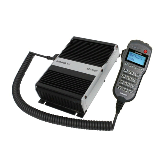
SDM622
User Manual
Issue: 1.0
Document Number: TNM-U-E-0145
Date: October 2017
Field House,
Uttoxeter Old Road,
Derby.
DE1 1NH.
Tel: +44 (0) 1332 375500
Fax: +44 (0) 1332 375501
www.simocowirelesssolutions.com
1270 Ferntree Gully Road,
Scoresby Victoria,
3179
Australia.
Tel: +61 (0)3 9730 3999
Fax: +61 (0)3 9730 3988
www.simocowirelesssolutions.com
©2017 Simoco Wireless Solutions
Advertisement
Table of Contents


Need help?
Do you have a question about the SDM600 Series and is the answer not in the manual?
Questions and answers