Table of Contents
Advertisement
Quick Links
OPERATION AND MAINTENANCE MANUAL FOR SERIES
1702SB1 AND 1702P1 HEAVY DUTY IMPACTOOLS
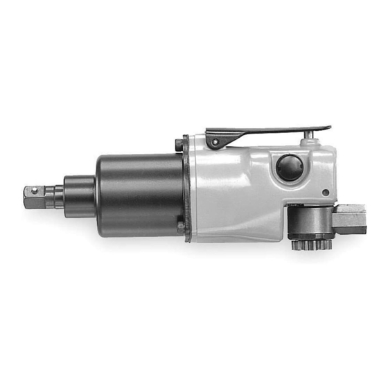
Model 1702SB1 and 1702P1 Impactools are designed for production applications and for
maintenance applications involving repair shops for light equipment such as lawn mowers
and garden tractors.
Ingersoll–Rand is not responsible for customer modification of tools for applications on
which Ingersoll–Rand was not consulted.
IT IS THE RESPONSIBILITY OF THE EMPLOYER TO PLACE THE INFORMATION
IN THIS MANUAL INTO THE HANDS OF THE OPERATOR.
FAILURE TO OBSERVE THE FOLLOWING WARNINGS COULD RESULT IN INJURY.
PLACING TOOL IN SERVICE
Always operate, inspect and maintain this tool in
accordance with American National Standards
Institute Safety Code for Portable Air Tools
(ANSI B186.1)
For safety, top performance, and maximum durability
of parts, operate this tool at 90 psig (6.2 bar/620 kPa)
maximum air pressure at the inlet with 5/16" (8 mm)
inside diameter air supply hose.
Always turn off the air supply and disconnect the air
supply hose before installing, removing or adjusting
any accessory on this tool, or before performing any
maintenance on this tool.
Do not use damaged, frayed or deteriorated air hoses
and fittings.
Be sure all hoses and fittings are the correct size and
are tightly secured. See Dwg. TPD905–1 for a typical
piping arrangement.
Always use clean, dry air at 90 psig (6.2 bar/620 kPa)
maximum air pressure. Dust, corrosive fumes and/or
excessive moisture can ruin the motor of an air tool.
Do not lubricate tools with flammable or volatile
liquids such as kerosene, diesel or jet fuel.
Do not remove any labels. Replace any damaged label.
USING THE TOOL
Always wear eye protection when operating or
performing maintenance on this tool.
Always wear hearing protection when operating this
tool.
The use of other than genuine Ingersoll–Rand replacement parts may result in safety hazards, decreased tool performance, and
increased maintenance, and may invalidate all warranties.
Repairs should be made only by authorized trained personnel. Consult your nearest Ingersoll–Rand Authorized Servicenter.
Refer All Communications to the Nearest
Ingersoll–Rand Office or Distributor.
Ingersoll–Rand Company 1999
Printed in U.S.A.
IMPORTANT SAFETY INFORMATION ENCLOSED.
READ THIS MANUAL BEFORE OPERATING TOOL.
03531548
Keep hands, loose clothing and long hair away from
rotating end of tool.
Note the position of the reversing lever before
operating the tool so as to be aware of the direction of
rotation when operating the throttle.
Anticipate and be alert for sudden changes in motion
during start up and operation of any power tool.
Keep body stance balanced and firm. Do not
overreach when operating this tool. High reaction
torques can occur at or below the recommended air
pressure.
Tool shaft may continue to rotate briefly after throttle
is released.
Air powered tools can vibrate in use. Vibration,
repetitive motions or uncomfortable positions may be
harmful to your hands and arms. Stop using any tool
if discomfort, tingling feeling or pain occurs. Seek
medical advice before resuming use.
Use accessories recommended by Ingersoll–Rand.
Use only impact sockets and accessories. Do not use
hand (chrome) sockets or accessories.
Impact wrenches are not torque wrenches.
Connections requiring specific torque must be
checked with a torque meter after fitting with an
impact wrench.
This tool is not designed for working in explosive
atmospheres.
This tool is not insulated against electric shock.
F
Form P6571
Edition 10
E
January, 1999
P
Advertisement
Table of Contents

Related Manuals for Ingersoll-Rand 1702SB1 Series


Summary of Contents for Ingersoll-Rand 1702SB1 Series
- Page 1 03531548 Form P6571 Edition 10 January, 1999 OPERATION AND MAINTENANCE MANUAL FOR SERIES 1702SB1 AND 1702P1 HEAVY DUTY IMPACTOOLS Model 1702SB1 and 1702P1 Impactools are designed for production applications and for maintenance applications involving repair shops for light equipment such as lawn mowers and garden tractors.
-
Page 2: Warning Label Identification
WARNING LABEL IDENTIFICATION FAILURE TO OBSERVE THE FOLLOWING WARNINGS COULD RESULT IN INJURY. WARNING WARNING WARNING Always turn off the air sup- Always wear eye protection Always wear hearing ply and disconnect the air when operating or perform- protection when operating supply hose before install- ing maintenance on this this tool. - Page 3 6,2 bar (620 kPa). La poussière, les Utiliser les accessoires recommandés par fumées corrosives et/ou une humidité excessive pvent Ingersoll-Rand. endommager le motr d’un outil pnmatique. N’utiliser que les douilles et les accessoires pour clés à Ne jamais lubrifier les outils avec des liquides chocs.
-
Page 4: Mise En Service De L'outil
SIGNIFICATION DES ETIQUETTES D’AVERTISSEMENT ATTENTION LE NON RESPECT DES AVERTISSEMENTS SUIVANTS PT CAUSER DES BLESSURES ATTENTION ATTENTION ATTENTION Couper toujours l’alimentation Porter toujours une Porter toujours des lunettes d’air comprimé et débrancher le protection acoustique de protection pendant flexible d’alimentation avant pendant l’utilisation de cet l’utilisation et l’entretien de d’installer, déposer ou ajuster... -
Page 5: Spécifications
MISE EN SERVICE DE L’OUTIL SPÉCIFICATIONS Modèle Poignée à Entraînement Coups par Gamme de levier minute couples recommandée ft–lbs (Nm) 1702SB1 en ligne 1/2” carré 1.500 13–85 (18–115) 1702P1 pistolet 1/2” carré 1.500 15–100 (21–136) - Page 6 MANUAL DE USO Y MANTENIMIENTO PARA LLAVES DE IMPACTO DE SERVICIO PESADO DE LAS SERIES 1702SB1 Y 1702P1 NOTA Las llaves de impacto modelos 1702SB1 y 1702P1 están diseñadas para trabajos de producción y de mantenimiento en talleres de reparación de equipos ligeros tales como máquinas de cortar césped y tractores hortícolas.
-
Page 7: Etiquetas De Aviso
ETIQUETAS DE AVISO AVISO EL HACER CASO OMISO DE LOS AVISOS SIGUIENTES PODRÍA OCASIONAR LESIONES. ADVERTENCIA ADVERTENCIA ADVERTENCIA Cortar siempre el suministro Usar siempre protección ocular Usar siempre protección de aire y desconectar la man- al manejar o realizar opera- para los oídos al manejar guera de suministro de aire ciones de mantenimiento en... -
Page 8: Especificaciones
ESPECIFICACIONES Modelo Tipo de Accionamiento Impactos por Gama de par Empuñadura minuto recomendada pulg. ft–lbs (Nm) 1702SB1 en linea 1/2” cuadradillo 1.500 13–85 (18–115) 1702P1 pistola 1/2” cuadradillo 1.500 15–100 (21–136) - Page 9 MANUAL DE FUNCIONAMENTO E MANUTENÇÃO PARA AS FERRAMENTAS DE PERCUSSÃO PARA TRABALHO PESADO 1702SB1 E 1702P1 AVISO As Ferramentas de Percussão Modelos 1702SB1 e 1702P1 são concebidas para aplicações de produção e de manutenção que envolvam oficinas de reparação para equipamento ligeiro como corta–relvas e tractores para jardinagem.
- Page 10 IDENTIFICAÇÃO DO RÓTULO DE ADVERTÊNCIA ADVERTÊNCIA O NÃO CUMPRIMENTO DAS SEGUINTES ADVERTÊNCIAS PODE RESULTAR EM FERIMENTO. ADVERTÊNCIA ADVERTÊNCIA ADVERTÊNCIA Use sempre óculos de Use sempre protecção contra o Desligue sempre a alimentação protecção quando estiver ruído ao operar esta ferramenta. de ar e desconecte a mangueira operando ou executando algum de alimentação de ar antes de...
- Page 11 ESPECIFICAÇÕES Modelo Tipo de Pega Accionamento Impactos por Gama de Binário min. Recomendada pol. ft–lbs (Nm) 1702SB1 en linha 1/2 pol. quadr. 1.500 13–85 (18–115) 1702P1 pistola 1/2 pol. quadr. 1.500 15–100 (21–136)
- Page 12 SERIES 1702SB1 (Dwg. TPA978–2)
- Page 13 PART NUMBER FOR ORDERING PART NUMBER FOR ORDERING Motor Housing Assembly ....1702SB–A40 Nameplate Screw (3) ....BN403–302 Throttle Valve .
- Page 14 PART NUMBER FOR ORDERING PART NUMBER FOR ORDERING Hammer Case Gasket ....401–36 Body Lock Pin ..... . I0A902A5–936 Hammer Case Cap Screw (3) .
- Page 15 SERIES 1702P NOTE: PRESS THIS PIN INTO AND OUT OF THE OPPOSITE SIDE OF THE HOUSING. ASSEMBLED HAMMER CASE ASSEMBLED 212–23 EXHAUST MUFFLER KIT HAMMER CASE (AVAILABLE AT EXTRA COST) (Dwg. TPA979–3)
- Page 16 PART NUMBER FOR ORDERING PART NUMBER FOR ORDERING Motor Housing Assembly ....1702P–A40 Nameplate ......1702P–301 Inlet Bushing .
- Page 17 PART NUMBER FOR ORDERING PART NUMBER FOR ORDERING Hammer Case Assembly ....1702–A727 Quick–Change Anvil Assembly ....1702–A926–7 Hammer Case Bushing .
-
Page 18: Maintenance Section
MAINTENANCE SECTION Power Adjustment of 1702P1 for Running Left– Hand Thread Fasteners Always wear eye protection when operating or While facing the back of the Impactool, push the performing maintenance on this tool. Reverse Valve (4) to the extreme right position. Rotate the Reverse Valve so the desired power setting Always turn off the air supply and disconnect the air is aligned with the small indicator line on the Motor... - Page 19 MAINTENANCE SECTION Disassembly of the Impact Mechanism for Using a punch, carefully drive the Throttle Lever Pin (6) from the Motor Housing and remove the Throttle 1702P1 lever (5). Grasp the Motor Housing (1) in vise jaws, square Hold the Motor Housing firmly in a vise, taking care driver upward.
- Page 20 MAINTENANCE SECTION 7. Using a pin punch, tap out the Throttle Valve Retain- 7. Align the holes in the Throttle Lever (5) with the ing Pin (14) to release the Throttle Valve from the holes in the boss on top of the Motor Housing and Throttle Valve Bushing.
- Page 21 MAINTENANCE SECTION 6. Insert the Throttle Valve into the Throttle Valve 7. If the Front Rotor Bearing (23) was removed, press a Bushing, taking care to line up the retaining pin hole new Bearing into the recess of the Front End in the Throttle Valve with the elongated hole in the Plate (29).
- Page 22 MAINTENANCE SECTION Assembly of the Impact Mechanism for 1702SB1 Assembly of the Impact Mechanism for 1702P1 Place the Hammer Frame Washer (35) over the 1. Place the Hammer Frame Washer (37) over the splined hub of the Rotor and against the Front Rotor splined hub of the Rotor and against the Front Rotor Bearing.
-
Page 23: Troubleshooting Guide
TROUBLESHOOTING GUIDE Trouble Probable Cause Solution Low power Dirty Inlet Bushing and/or Air Using a clean, suitable cleaning solution in a well Strainer Screen and/or Exhaust ventilated area, clean Air Strainer Screen, Inlet Silencer Bushing and Exhuast Silencer. Worn or broken Vanes Replace the complete set of Vanes.
Need help?
Do you have a question about the 1702SB1 Series and is the answer not in the manual?
Questions and answers