Table of Contents
Advertisement
Quick Links
P25 SRM9030/SRM9030
P25 – CONVENTIONAL/TRUNKED OPERATING
Field House,
Uttoxeter Old Road
Derby
DE1 1NH
Tel:
+44 (0) 1332 375500
FAX:
+44 (0) 1332 375501
http://www.simocogroup.com
RADIO
INSTRUCTIONS
TNM-U-E-0094, Issue 2.0
October 2015
© Simoco 2015
Plus
MOBILE
1270 Ferntree Gully Road,
Scoresby
Victoria, 3179
Australia
Tel:
+61 (0)3 9730 3999
FAX: +61 (0)3 9730 3988
http://www.simocogroup.com
Advertisement
Table of Contents

Related Manuals for Simoco P25 SRM9030


Summary of Contents for Simoco P25 SRM9030
-
Page 1: Title Page
Plus P25 SRM9030/SRM9030 MOBILE RADIO P25 – CONVENTIONAL/TRUNKED OPERATING INSTRUCTIONS TNM-U-E-0094, Issue 2.0 October 2015 1270 Ferntree Gully Road, Field House, Scoresby Uttoxeter Old Road Victoria, 3179 Derby Australia DE1 1NH Tel: +61 (0)3 9730 3999 Tel: +44 (0) 1332 375500... -
Page 2: Preface
OPYRIGHT All information contained in this document is the property of Simoco. All rights are reserved. This document may not, in whole or in part, be copied, photocopied, reproduced, translated, stored, or reduced to any electronic medium or machine-readable form, without prior written permission from Simoco. - Page 3 TNM-U-E-0102 SRP9180 Brief User Guide (General) To order printed copies of this or any of the above publications, please contact Simoco. See the Support page for contact information. A comprehensive list of documentation is available for download on the Simoco website http://www.simocogroup.com...
-
Page 4: Table Of Contents
Table of Contents (this list) ......................4 List of Figures ..........................7 List of Tables ..........................7 PERSONAL SAFETY ........................8 WEEE Notice ..........................10 General Notes ..........................11 Simoco Support ......................... 12 Abbreviations ..........................13 Glossary ............................. 14 INTRODUCTION ......................... 16 ........................16 VERVIEW ....................... - Page 5 Plus P25 SRM9030/9030 – OPERATING INSTRUCTIONS TNM-U-E-0094 Phone Book Edit – To Add a New Entry ..............29 5.6.2 Phone Book Edit – To Edit an Existing Entry ............30 5.6.3 5.6.3.1 System ID ..................... 30 5.6.3.2 WACN ID ...................... 31 5.6.3.3...
- Page 6 Plus P25 SRM9030/9030 – OPERATING INSTRUCTIONS TNM-U-E-0094 SPECIAL FUNCTION KEYS ....................55 ..........................55 LARM ........................55 NNOUNCE ....................55 HANNEL ........................... 55 RYPTO DTMF S 1/2 (P25 A ) ..................55 NALOGUE ........................55 OWER ..........................56 ..........................56 ..........................
-
Page 7: List Of Figures
Plus P25 SRM9030/9030 – OPERATING INSTRUCTIONS TNM-U-E-0094 LIST OF FIGURES Page Figure 1. SRM9030 Control Head....................17 Figure 2. SRM9030Plus Control Head..................17 Figure 3. Main/Default screen (SRM9030Plus example).............. 19 Figure 4. Icon Locations....................... 20 Figure 5. Menu Navigation......................23 Figure 6. -
Page 8: Personal Safety
Plus P25 SRM9030/9030 – OPERATING INSTRUCTIONS TNM-U-E-0094 PERSONAL SAFETY AFETY RECAUTIONS These Safety Precautions, Warnings and Cautions advise personnel of specific hazards which may be encountered during the procedures contained in this document and that control measures are required to prevent injury to personnel, and damage to equipment and/or the environment. - Page 9 Plus P25 SRM9030/9030 – OPERATING INSTRUCTIONS TNM-U-E-0094 WARNING DANGEROUS VOLTAGES. DANGEROUS VOLTAGES EXIST IN THIS EQUIPMENT. FOR THE APPROPRIATE SAFETY PRECAUTIONS REFER TO THE RELEVANT ELECTRICAL SAFETY REGULATIONS APPROPRIATE TO THE COUNTRY OF OPERATION. HINTS FOR USING THE RADIO When transmitting, hold the microphone a few centimetres from your mouth and speak across it, rather than into it.
-
Page 10: Weee Notice
Plus P25 SRM9030/9030 – OPERATING INSTRUCTIONS TNM-U-E-0094 WASTE ELECTRICAL AND ELECTRONIC EQUIPMENT (WEEE) NOTICE The Waste Electrical and Electronic Equipment (WEEE) Directive became law in most EU countries during 2005. The directive applies to the disposal of waste electrical and electronic equipment within the member states of the European Union. -
Page 11: General Notes
Plus P25 SRM9030/9030 – OPERATING INSTRUCTIONS TNM-U-E-0094 GENERAL NOTES ANUAL OMPILATION This manual provides information on using the SRM9030/SRM9030Plus P25 Mobile Radio. Details of both ‘basic’ and ‘optional units’ have been included in this User Manual, therefore, some material may not be relevant to every system. Configuration is dependent upon the specification by the customer when the equipment was ordered and installed. -
Page 12: Simoco Support
ECHNICAL UPPORT In order to streamline support requests and better serve our customers, at Simoco we utilize a support ticket system. Every support request is assigned a unique ticket number, which customers can use to track the progress and responses online. For reference, Simoco provide complete archives and history of all customer support requests. - Page 13 Plus P25 SRM9030/9030 – OPERATING INSTRUCTIONS TNM-U-E-0094 Technical Support Email Addresses Simoco EMEA: techsupport@simocogroup.com Simoco Australasia: inquiry.aus@simocogroup.com Simoco Americas: techsupport@simocogroup.com Technical Support Helplines Simoco EMEA: Tel: 08717 411 040 International: +44 (0) 1332 375 671 Simoco Australasia: Tel: Within Australia:...
-
Page 14: Abbreviations
Plus P25 SRM9030/9030 – OPERATING INSTRUCTIONS TNM-U-E-0094 ABBREVIATIONS The following abbreviations are used throughout this document. Wherever practicable, whenever the abbreviation is first used, the full meaning is given with the abbreviation in parenthesis, after that only the abbreviation will be used. -
Page 15: Glossary
Plus P25 SRM9030/9030 – OPERATING INSTRUCTIONS TNM-U-E-0094 GLOSSARY OF TERMS A summary of common radio terms and some other terms used in this document, and their meanings, are given below. Bank See Zone. Channel A logical combination of: Network Access Code (NAC); Radio Frequency; Default Talk Group Identity (TGID);... -
Page 16: Introduction
TNM-U-E-0094 INTRODUCTION VERVIEW The Simoco SRM9000 Series Radios are a family of versatile Digital Signal Processor (DSP) controlled, software defined two-way mobile radios. This User Manual describes the operation of the Association of Public safety Communications Officials (APCO) P25 Standard compliant Mobile Radio, which consists of an SRM9000 Transceiver, a MA-MAB-2/4 Option Board, and an SRM9030/SRM9030Plus Control Head. -
Page 17: Controls
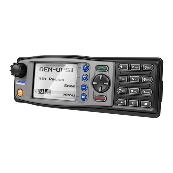
Plus P25 SRM9030/9030 – OPERATING INSTRUCTIONS TNM-U-E-0094 CONTROLS The SRM9030 Control Head has the following features: 11 programmable direct Function Buttons. 10 additional indirect Function Buttons (keys 0 – 9). 1500 Channels. 40 Zones. 250 Channels per zone. -
Page 18: Table 1. Srm9030 - Control Functions
Plus P25 SRM9030/9030 – OPERATING INSTRUCTIONS TNM-U-E-0094 The functions of each of the controls are detailed in below Table 1. Table 1. SRM9030 – Control Functions. Label SRM9030 Key Function (9030/9030Plus) To turn the radio on, press and hold the volume knob for Power On/Off about 1 second. -
Page 19: Main Screen
Plus P25 SRM9030/9030 – OPERATING INSTRUCTIONS TNM-U-E-0094 MAIN SCREEN AYOUT An example of the main or default screen that is displayed when the radio is switched on is shown below in Figure 3. Channel Menu Name Zone Name RSSI Bars Icon Area Figure 3. -
Page 20: Figure 4. Icon Locations
Plus P25 SRM9030/9030 – OPERATING INSTRUCTIONS TNM-U-E-0094 Menu Icon Area Figure 4. Icon Locations. Table 2. Icon Locations. Position Icons Message Talk Around Other Signal Scanning Signal Monitor Normal Selective Connecting Connect Fail Digital Encrypted Scrambler Trunking Locked Keypad Individual Call Oct 15 (Iss. -
Page 21: Table 3. Icon Details
Plus P25 SRM9030/9030 – OPERATING INSTRUCTIONS TNM-U-E-0094 Details of the Icons that can be displayed in the Icon Area are contained below in Table 3. Table 3. Icon Details. ICON INDICATION A filled speaker icon indicates that a signal is present and the audio can be heard from the speaker. -
Page 22: Menu System
Plus P25 SRM9030/9030 – OPERATING INSTRUCTIONS TNM-U-E-0094 MENU SYSTEM This section details the operation of the menu system for the SRM9030. The SRM9030 has a menu system that is configurable by the FPP. The FPP has a pool of menu entries that can be applied as required in the order required. -
Page 23: Figure 5. Menu Navigation
Plus P25 SRM9030/9030 – OPERATING INSTRUCTIONS TNM-U-E-0094 To access this, you can press the ‘F1’ or menu key from the channel screen and then the numeric key assigned to that function. Back Note: Example menus only shown. Back Squelch Submenu Other Menus may be configured with the FPP. -
Page 24: Menu Screens
Plus P25 SRM9030/9030 – OPERATING INSTRUCTIONS TNM-U-E-0094 MENU SCREENS The menu structure on the SRM9030 is configurable using the FPP. A system administrator usually tailors the order and presence of the menu options to specific customer requirements. This section describes all the menus that are currently available. It also describes the Channel Screen, which is the main default screen that is displayed after the radio is switched on. -
Page 25: Zone Menu
Plus P25 SRM9030/9030 – OPERATING INSTRUCTIONS TNM-U-E-0094 The Zone Screen is used for changing Zones. A Zone is normally defined as a group of radio channels with a common operational role. When the ‘Zone’ menu option is displayed, press the OK button to enter the ‘Zone’ select screen. -
Page 26: Digital Operation
Plus P25 SRM9030/9030 – OPERATING INSTRUCTIONS TNM-U-E-0094 For a P25 digital channel, the ▼/▲ keys can be used to select either Monitor, Normal or Selective squelch mode. For an analogue channel, the ▼/▲ keys can be used to select either Monitor or Normal squelch mode. -
Page 27: Phone Book Menu
Plus P25 SRM9030/9030 – OPERATING INSTRUCTIONS TNM-U-E-0094 With the Mute Adjust menu option displayed, press the OK key to access the Mute Adjust screen. A numeric value of the present mute level will be displayed. Use the ▼/▲ keys to adjust the mute threshold as required. Press the OK key confirm the selected mute setting and return to the default channel screen. -
Page 28: Making An Individual Call
Plus P25 SRM9030/9030 – OPERATING INSTRUCTIONS TNM-U-E-0094 To return to the Menu screen, press either the Back or Menu keys. A function key (when configured for Reset, or any other key configured for Reset) will exit back to the default channel screen. -
Page 29: Phone Book Edit - To Delete An Entry
Plus P25 SRM9030/9030 – OPERATING INSTRUCTIONS TNM-U-E-0094 The pop-up menu items are: Add. Used to add a new phone book entry. Edit. Used to edit (modify) the selected phone book entry. Delete. Used to delete the currently selected phone book entry. -
Page 30: Phone Book Edit - To Edit An Existing Entry
Plus P25 SRM9030/9030 – OPERATING INSTRUCTIONS TNM-U-E-0094 From here, follow the steps for entering the System ID in Section 5.6.3.1 below (part of Section 5.6.3 Phone Book Edit – To Edit an Existing Entry). 5.6.3 Phone Book Edit – To Edit an Existing Entry This section is used to edit an existing phone book entry. -
Page 31: Wacn Id
Plus P25 SRM9030/9030 – OPERATING INSTRUCTIONS TNM-U-E-0094 If the System ID has to be changed, use the keypad and the ▼ key to enter the new System ID as required and then press the OK key. If the system ID does not have to be changed, press the OK key. -
Page 32: Name
Plus P25 SRM9030/9030 – OPERATING INSTRUCTIONS TNM-U-E-0094 The IP address can be changed using the numeric digits and the ▼/▲ keys to move the cursor with the ▼ function key as a destructive backspace. The ‘#’ key is used to enter a “.” (full stop). -
Page 33: User Options Menu
Plus P25 SRM9030/9030 – OPERATING INSTRUCTIONS TNM-U-E-0094 The Setup menu structure may include, for example: User Options; Contrast; Alert Volume; Crypto Key (Select Transmit Encryption Key); Radio Info (Radio software and hardware information); RSSI;... -
Page 34: Contrast Menu
Plus P25 SRM9030/9030 – OPERATING INSTRUCTIONS TNM-U-E-0094 Pressing the Back or Menu key saves all the function settings and returns to the next highest menu level. ONTRAST The Contrast menu allows the screen’s contrast setting to be altered. From the Setup menu, use the ▼/▲ keys to scroll through sub-menus and, with the Contrast menu option displayed, press the OK key to access the Contrast adjustment screen. -
Page 35: Radio Information Menu
Plus P25 SRM9030/9030 – OPERATING INSTRUCTIONS TNM-U-E-0094 Use the ▼/▲ keys to adjust the alert volume numeric setting as required. A beep will sound at the indicated level each time the setting is changed. Press the OK key to save the changes and return to the main channel screen. -
Page 36: Mode Menu
Plus P25 SRM9030/9030 – OPERATING INSTRUCTIONS TNM-U-E-0094 Application SW Ver. & Date Application Upgrade Ver., Date & PLA Code P25 Radio Unit Trunked ID and IP Addr. P25 Trunked SysID, WACN, GID and UID Feature Authorisation Enables Encryption Status Encryption Summary External Application Memory Status The ‘Radio Info’... -
Page 37: Rssi Menu
Plus P25 SRM9030/9030 – OPERATING INSTRUCTIONS TNM-U-E-0094 When the Mode screen is displayed, use the ▼/▲ keys to scroll through and select the required operating mode, such as APCO P25, PMR or MPT Trunking. When the required mode is displayed, press the OK key to select that operating mode. The radio will then display the default screen for that mode. -
Page 38: Crypto Key Menu
Plus P25 SRM9030/9030 – OPERATING INSTRUCTIONS TNM-U-E-0094 If a digital channel is selected, the BER will also be displayed. The RSSI/BER will be displayed until either the Menu key is pressed to return to the next highest menu level or the OK key is pressed to return to the main channel screen. -
Page 39: Stored Calls Menu
Plus P25 SRM9030/9030 – OPERATING INSTRUCTIONS TNM-U-E-0094 Press the OK key to save the changes and return to the main channel screen. Press the Back or Menu key to save the changes and return to the next highest menu level. -
Page 40: 5.15.2 To Delete A Stored Call Record
Plus P25 SRM9030/9030 – OPERATING INSTRUCTIONS TNM-U-E-0094 Press the PTT button within the configured time interval and an individual call to the ID of the stored call will be sent. 5.15.2 To Delete a Stored Call Record From the Stored Calls screen, use the ▼/▲ keys to scroll through and select the required stored call record from the list. -
Page 41: 5.16.2 View Received Messages Screen
Plus P25 SRM9030/9030 – OPERATING INSTRUCTIONS TNM-U-E-0094 SMSG. Short Message. The radio can be programmed with a list of predefined messages. Selecting SMSG shows a list of predefined short messages, which can be sent to another radio unit. Only applicable when a digital channel is selected. -
Page 42: Messages View - Pop-Up Menu
Plus P25 SRM9030/9030 – OPERATING INSTRUCTIONS TNM-U-E-0094 5.16.2.1 Messages View – Pop-Up Menu The Messages View pop-up menu selections are: DELETE – to delete the currently selected message. MORE – to view the full (entire) message. REPLY – to select the method of replying to the selected message. -
Page 43: Messages Reply - Pop-Up Menu
Plus P25 SRM9030/9030 – OPERATING INSTRUCTIONS TNM-U-E-0094 5.16.2.3 Messages Reply – Pop-Up Menu Selecting REPLY from the Messages View pop-up menu will bring up the Messages Reply pop- up menu. The Messages Reply pop-up menu selections are: CALL – to call the selected sender. -
Page 44: Text Message Reply Screen
Plus P25 SRM9030/9030 – OPERATING INSTRUCTIONS TNM-U-E-0094 Press the Menu or Back key to return to the next highest menu screen. Press the ‘Reset’ function key (if configured) to return to the default screen without sending a short message reply. -
Page 45: Text Message Screen
Plus P25 SRM9030/9030 – OPERATING INSTRUCTIONS TNM-U-E-0094 This screen allows the user to view and select a short message. It displays the selected short message text. The short message can be selected by using the ▼ and ▲ keys. Press the ‘Reset’ function key (if configured) to return to the default screen without sending a message. -
Page 46: Phonebook Entry Selection Screen
Plus P25 SRM9030/9030 – OPERATING INSTRUCTIONS TNM-U-E-0094 The selections are: PH.BK – to select the destination from the phone book. ENT.ID – to enter the destination Unit ID. CANCEL – to cancel the destination selection. Use the ▼/▲ keys to select the require option. -
Page 47: Scan Edit Menu
Plus P25 SRM9030/9030 – OPERATING INSTRUCTIONS TNM-U-E-0094 The entered digits can be deleted by using the ▼ key. Press the Menu or Back key to return to the Destination Selection pop-up menu screen. Press the ‘Reset’ function key (if configured) to return to the default screen display. - Page 48 Plus P25 SRM9030/9030 – OPERATING INSTRUCTIONS TNM-U-E-0094 The next line shows the channel type, i.e. ‘Member’ if it is a normal member of the scan group, ‘Priority’ if it is the priority channel, or ‘Skipped’ if the channel is currently skipped from the scan group.
-
Page 49: 5.17.2 Scan Group Add Screen
Plus P25 SRM9030/9030 – OPERATING INSTRUCTIONS TNM-U-E-0094 Press the Menu or Back key to return to the next highest menu screen. Press the ‘Reset’ function key (if configured) to return to the default screen. 5.17.2 Scan Group Add Screen The Scan Group Add screen shows channels that are not members of the Scan Group. -
Page 50: Common Functions And Facilities
Plus P25 SRM9030/9030 – OPERATING INSTRUCTIONS TNM-U-E-0094 COMMON FUNCTIONS AND FACILITIES WITCH WITCH The On/Off power switch on the SRM9030 is on the rotary volume control, located on the top left- hand side of the radio control head. To turn the mobile on, press and hold the volume knob until a beep is heard. The radio will turn on after about one second. -
Page 51: Received Individual Calls
Plus P25 SRM9030/9030 – OPERATING INSTRUCTIONS TNM-U-E-0094 The Solid Speaker Icon will be displayed when a valid signal is being received and audio will be heard at the loudspeaker. An Outline Speaker Icon will be displayed if a signal is being received that is not addressing this radio and, hence, is not audible. -
Page 52: Transmitting
Plus P25 SRM9030/9030 – OPERATING INSTRUCTIONS TNM-U-E-0094 RANSMITTING WARNING RADIO FREQUENCY RADIATION. A RF RADIATION HAZARD EXISTS IN THIS EQUIPMENT. TO AVOID RF INJURY, DO NOT TOUCH THE ANTENNA WHEN THE TRANSMITTER IS IN USE. DO NOT OPERATE TRANSMITTER WITH ANTENNA DISCONNECTED. REFER TO THE PERSONAL SAFETY PAGES. -
Page 53: Scan/Vote Screen
Plus P25 SRM9030/9030 – OPERATING INSTRUCTIONS TNM-U-E-0094 If a Priority Channel is assigned to Scan mode, the radio will interleave a check of this channel between each normal Scan channel. 6.6.1 Scan/Vote Screen A Scan can be started by: ... -
Page 54: Encryption
Plus P25 SRM9030/9030 – OPERATING INSTRUCTIONS TNM-U-E-0094 NCRYPTION In P25 Digital mode, radio channels may be programmed for encryption. The encryption state of the selected channel is determined by the radio configuration. An encrypted channel will display the encryption icon. -
Page 55: Special Function Keys
Section 5. This section lists Functions that may be programmed to the programmable function keys. Consult Simoco for those functions that have been programmed in to your radio. LARM The Alarm function key (default F5) is used to put the radio into Emergency Mode. -
Page 56: Menu
Plus P25 SRM9030/9030 – OPERATING INSTRUCTIONS TNM-U-E-0094 The RF power level is indicated by the letter L of H replacing the antenna icon when transmitting. The bar graph above this icon shows one bar for low power and six bars for high power. -
Page 57: Scan Edit
Plus P25 SRM9030/9030 – OPERATING INSTRUCTIONS TNM-U-E-0094 Note. If Auto-scan is programmed for that channel, the Scan key will not function. 7.13 S This key is used to enter the Scan Edit menu, where the members of a scan group can be added or deleted. -
Page 58: Figure 7. Alert Tones
Plus P25 SRM9030/9030 – OPERATING INSTRUCTIONS TNM-U-E-0094 APPENDIX A ALERT TONES AND MESSAGES 0.05 440 Hz Key Beep 880 Hz 0.05 1480 Hz Duration Indicated in seconds Grant Tone 0.05 Error Tone 0.10 Beep Alert 0.10 Bip Alert 0.10 2 x Bip Alert... - Page 59 NSTRUCTIONS CCUPATIONAL EQUIREMENTS Before using your Simoco mobile two-way radio, it is important that you read these RF Energy Awareness and Control Information and Operational Instructions in order to ensure compliance with the Federal Communications Commission’s (FCCs) RF Exposure Guidelines.
- Page 60 XPOSURE TANDARDS Your Simoco two-way radio is designed to comply with a number of national and international standards and guidelines (listed below) regarding human exposure to RF electromagnetic energy. This radio complies with the Institute of Electrical and Electronic Engineers (IEEE), FCC and the...
-
Page 61: Table 4(A). Rated Power And Recommended Lateral Distance For General Population
Plus P25 SRM9030/9030 – OPERATING INSTRUCTIONS TNM-U-E-0094 (iii). Table 6(a) lists the recommended minimum lateral distance for bystanders in an uncontrolled environment from the transmitting antenna for the SRM9000X8 (806 MHz – 870 MHz) mobile rated power (25 Watts) installed in a vehicle. Table 6(b) lists the recommended minimum lateral distance for occupational/ controlled use. - Page 62 FCC regulations. Approved Accessories This radio meets the FCC RF exposure guidelines when used with the Simoco accessories supplied or designated for the product. Use of other accessories may not ensure compliance with the FCC’s RF exposure guidelines and may violate FCC regulations.
- Page 63 SIMOCO GROUP Global Headquarters: Field House, Uttoxeter Old Road, Derby DE1 1NH United Kingdom: Tel: 08717 411 050 Fax: 08717 411 049 International: Tel: +44 (0) 1332 375 671 Fax: +44 (0) 1332 375 672 www.simocogroup.com SIMOCO AUSTRALASIA 1270 Ferntree Gully Road, Scoresby, Victoria, 3179, Australia...
Need help?
Do you have a question about the P25 SRM9030 and is the answer not in the manual?
Questions and answers