Table of Contents
Advertisement
Quick Links
Advertisement
Table of Contents

Related Manuals for DivioTec NFF271


Summary of Contents for DivioTec NFF271
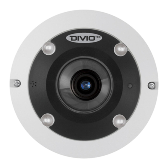
- Page 1 Hyper Mini Fisheye IP Camera NFF271 User’s Manual Ver. 1.2 001B0DZXZ2A2...
-
Page 2: Table Of Contents
Table of Contents Overview ..........................2 Features ........................2 Package Contents ....................... 3 Dimensions ........................5 Connectors (Camera without IP66) ................6 Function Cables (Camera with IP66) ................7 Camera Cabling ........................8 Power Connection ....................... 8 Ethernet Cable Connection ..................8 Waterproof Cable Connector (Camera with IP66) ............ -
Page 3: Overview
Overview The Hyper Mini Fisheye IP Camera is a high resolution surveillance solution features 360° wide coverage without blind spots. The fisheye camera supports resolution up to 6 Megapixels streaming at 30 fps which allows the videos to be viewed smoothly. Moreover, the fisheye camera supports digital PTZ, panoramic view and several display modes to fulfill users’... -
Page 4: Package Contents
Package Contents Please check the package contains the following items listed below. Camera without IP66 Hyper Mini Fisheye IP Self-Tapping Screw (x3) Plastic Anchor (x3) Camera Security Torx Power Terminal Quick Guide Block NOTE: The supplied self-tapping screws are for soft substance / material installation such as wood. - Page 5 Camera with IP66 Hyper Mini Fisheye Self-Tapping Screw Plastic Anchor (x3) Security Torx IP Camera (x3) Power Terminal Alarm I/O Terminal Quick Guide Block Block NOTE: The supplied self-tapping screws are for soft substance / material installation such as wood. For other installation environment such as cement wall, it is required to pre-drill and use plastic anchors before fastening the supplied self-tapping screws on the wall.
-
Page 6: Dimensions
Dimensions The dimensions of the camera are shown below. -
Page 7: Connectors (Camera Without Ip66)
Connectors (Camera without IP66) Please loosen the security screws and open the cover to reach the connectors. The diagram below shows the connectors of the camera. Definition for each connector is given as follows. Connector Definition Remarks DC 12V Power DC 12V Power connection Reserved... -
Page 8: Function Cables (Camera With Ip66)
Function Cables (Camera with IP66) Connector Definition Remarks Pink Audio In Audio I/O Two-way audio transmission Green Audio Out DC 12V – Black Power (DC 12V) Power connection (2-Pin Terminal Block) DC 12V + Alarm In – Alarm In + Alarm I/O Alarm connection Alarm Out –... -
Page 9: Camera Cabling
Camera Cabling Please follow the instructions below to complete the cable connections. Power Connection For power connection, please refer to section Connectors (Camera without IP66) for the indoor models, and see section Function Cables (Camera with IP66) the outdoor models. Alternatively, users can power the camera by PoE if a Power Sourcing Equipment (PSE) switch is available. -
Page 10: Waterproof Cable Connector (Camera With Ip66)
Waterproof Cable Connector (Camera with IP66) Follow the instruction below to waterproof the connectors of different types of cables. The supported cables are as shown below. All-in-One Cable IP66 RJ-45 Cable All-in-One Cable Follow the steps below to waterproof the connectors of the All-in-One cable. Step 1: Connect required... - Page 11 IP66 RJ-45 Cable For IP66 RJ-45 cable, please use an RJ-45 IP66 plug for connection to prevent water damage. Follow the steps below for cable connection. Step 1: Take out the supplied connector from the RJ-45 IP66 plug. Loosen the thread-lock sealing nut on the plug.
-
Page 12: System Requirements
System Requirements To perform the IP camera via web browser, please ensure the PC is in good network connection, and meet system requirements as described below. Items System Requirement Minimum : ® 1. Intel Core™ i5-2430M @ 2.4 GHz 2. 4 GB RAM Personal Computer Recommended: Core™... -
Page 13: Access Camera
Access Camera For initial access to the IP camera, users can search the camera through the installer program: DeviceSearch.exe, which can be found in “DeviceSearch” folder in the supplied CD. Accessing the Camera by Device Search Software Step 1: Double click on the program Device Search.exe. Step 2: After its window appears, click on the <Device Search>... - Page 14 Step 8: A prompt window requesting for default username and password will appear. Enter the default username and password shown below to login to the camera. Login ID Password Admin 1234 NOTE: ID and password are case sensitive. NOTE: It is strongly advised that administrator’s password be altered for the security concerns.
- Page 15 Once the Viewer is successfully installed, the Home page of the IP camera will be shown as the figure below. Ceiling Mount Installed Camera...
- Page 16 Wall Mount Installed Camera...
-
Page 17: Setup Video Resolution
Setup Video Resolution Users can setup video resolution on Video Format page of the user-friendly browser-based configuration interface. Video Format can be found under this path: Streaming> Video Format. The default video resolution of 5M and 6M models are shown as below. The default resolution varies with different Fisheye Dewarping types, Front End Camera Dewarping and Back End Software Dewarping. -
Page 18: Configuration Files Export / Import
Configuration Files Export / Import To export / import configuration files, users can access the Maintenance page on the user-friendly browser-based configuration interface. The Maintenance setting can be found under this path: System> Maintenance. Users can export configuration files to a specified location and retrieve data by uploading an existing configuration file to the camera. -
Page 19: Tech Support Information
Tech Support Information This chapter will introduce how to delete previously-installed Viewer in the PC and how to setup the Internet security. Delete the Existing Viewer For users who have installed the Viewer in the PC previously, please remove the existing Viewer from the PC before accessing to the IP camera. Deleting the Viewer In the Windows <Start Menu>, activate <Control Panel>, and then double click on <Add or Remove Programs>. -
Page 20: Setup Internet Security
Setup Internet Security If ActiveX control installation is blocked, please either set Internet security level to default or change ActiveX controls and plug-ins settings. Internet Security Level: Default Step 1: Start the Internet Explorer (IE). Step 2: Click on the <Tools> tab on the menu bar and select <Internet Options>.
Need help?
Do you have a question about the NFF271 and is the answer not in the manual?
Questions and answers