Table of Contents
Advertisement
Quick Links
Advertisement
Table of Contents

Related Manuals for Runva HWP20000 Series


Summary of Contents for Runva HWP20000 Series
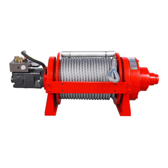
- Page 1 HYDRAULIC WINCH HWP/X20000 SERIES Assembly & Operating Instructions...
-
Page 2: Table Of Contents
LUBRICATION ..................12 CABLE ASSEMBLY REPLACEMENT ..........12 TROUBLE SHOOTING ................. 13 WINCH ASSEMBLY DRAWING HWP20000 SERIES ......14 WINCH PARTS LIST HWP20000 SERIES ........... 15 WINCH ASSEMBLY DRAWING HWX20000 SERIES ......16 WINCH PARTS LIST HWX20000 SERIES ........... 17 OUTLINE DIMENSIONAL DRAWING .......... -
Page 3: Introduction
INTRODUCTION 20000lb series winches are Runva totally new products up to the present in the world; each one owns several invention patents of Runva; Congratulations on your purchase of a highest class advanced powerful two speed winch. We design and build winches to strict specifications and with proper use and maintenance should bring you years of satisfying service. - Page 4 WARNING – Store idle equipment. When not in use, tools must be stored in a dry location to inhibit rust. Always lock up tools and keep out of reach of children. WARNING – Dress properly. Do not wear loose clothing or jewelry as they can be caught in moving parts.
-
Page 5: Winch Warnings And Precautions
WINCH WARNINGS AND PRECAUTIONS WARNING – Keep hands and body away from Fairlead (cable intake slot) when operating. WARNING – Secure vehicle in position before using winch. WARNING – Be certain winch is properly bolted to a structure (or vehicle) that can hold the winch load. -
Page 6: Unpacking
WARNING – Before operating the winch under load you should check proper function of the winch by engaging and disengaging the clutch, by operating the directional controls, and operating the speed controls. This will ensure that the winch is working properly and will help prevent unintended damage and injury. Cycling the winch prior to loading will also ensure the gears are properly aligned. - Page 7 The balance valve supplied is simply connected to motor. Be sure the balance valve’s installing direction meets hydraulic principle chart. Otherwise, the winch will not reach the rated line pull, and it is also dangerous for winch to power off the cable with heavy load.
- Page 8 U type A type The mounting drawing of U type The mounting drawing of A type...
- Page 9 Working hydraulic principle chart and installation illustration: Air actions clutch installation illustration: • Air clutch for Free spool • Air clutch for free spool and two speed HWP20000U/A/YP/YD--------Manual clutch operation of two speed HWP20000U1/A1/Y1P/Y1D-------Air clutch operation of single speed...
- Page 10 WARNING 1.Clutch in all the time, when clutch out, need pressure 87~130psi into winch 。 2.Pressure should not below 87psi。 3.When winch is loaded and working, Do not clutch out。 HWP20000U2U/A2Y2P /Y2D-------Air and manual mixed clutch operation of single speed WARNING 1 Pressure should not below 87psi.
-
Page 11: Operation
WARNING 1 Pressure should not below 87psi. 2 When winch is loaded and working. Do not clutch out. 3 Clutch must be fully engaged before winching. Caution: The hydraulic system needs a relief valve to ensure the system safety. The absence of such a valve could cause serious injury and damage the winch. - Page 12 The Winch’s standard equipments contain gear reducer、drum、hydraulic motor、 solenoid valve、switch assembly、female connector and plumbing fittings. The winch obtains its pressure from the vehicle’s existing power steering pump or other hydraulic power. The winch is totally sealed, can be used underwater. There are several other ways to supply power to the winch.
-
Page 13: Winch Accessories You Will Need
5. Test-run winch in both directions. Turn the winch in each direction for about one or two seconds meantime make the clutch totally engaged automatically. 6. While standing aside of the tow path, hold and operate the switch assembly supplied by your choice. Wait until the motor stops before reversing directions. 7. -
Page 14: Lubrication
For pulls over 70% rated line pull, we recommend the use of the snatch block/pulley block to double line the wire rope. Fig 3.4 This reduces the load on the winch and the strain on the rope by up Fig 3.4 to 50% depending on the included angle. -
Page 15: Trouble Shooting
TROUBLE SHOOTING SYMPTOM POSSIBLE CAUSE SUGGESTED ACTION -Insufficiently hydraulic -Check relief valve regulate pressure. system pressure. Winch does not -Check plumbing fixtures -Improper connections according to the working principle chart. turn . of hydraulic system, -Defective directional control valve. no oil into motor. -Turn the clutch to the high or lows peed Motor runs but - The clutch is Not... -
Page 16: Winch Assembly Drawing Hwp20000 Series
WINCH ASSEMBLY DRAWING HWP20000 SERIES... -
Page 17: Winch Parts List Hwp20000 Series
WINCH PARTS LIST HWP20000 SERIES Part # Description Remark Used in YP series HP2000001 Screw M12 x 35 Used in YD series Used in YP series Lock Washer Φ12 HP2000002 Used in YD series HP2000100-1 Used in YP series Hydraulic Motor... -
Page 18: Winch Assembly Drawing Hwx20000 Series
WINCH ASSEMBLY DRAWING HWX20000 SERIES... -
Page 19: Winch Parts List Hwx20000 Series
WINCH PARTS LIST HWX20000 SERIES Part # Description Remark Used in YP series HX2000001 Screw M12 x 35 Used in YD series Used in YP series Lock Washer Φ12 HX2000002 Used in YD series HX2000100-1 Used in YP series Hydraulic Motor HX2000100-2 Used in YD series HX2000003... -
Page 20: Outline Dimensional Drawing
OUTLINE DIMENSIONAL DRAWING HWP20000U HWP20000A HWP20000YP... - Page 21 HWP20000YD HWX20000YP HWX20000YD...
-
Page 22: Specification(Hwp20000U/A、U3/A3
SPECIFICATION(HWP20000U/A、U3/A3) Rated line pull 20000lbs (9072 kgs) Motor displacement 125ml/r Oil flow 5~45L/min Pressure 14.5Mpa Gear reduction ratio High speed: 6:1;Low speed: 39:1 Cable (Dia.× L) Ø9/16"×105 ' (Ø14mm×32m) Drum size(Dia.× L) Ø5.43 "×8. 9" (Ø138mm×226mm) Mounting bolt pattern 13.4"×2.5 "×7.6" (341mm×64mm×192mm) 8-M14 Item HWP20000U HWP20000A... -
Page 23: Specification(Hwp20000U1/A1、U2/A2
SPECIFICATION(HWP20000U1/A1、U2/A2) Rated line pull 20000 lbs (9072 kgs) Motor displacement 125ml/r Oil flow 5~45L/min Pressure 14.5Mpa Gear reduction ratio 39:1 Cable (Dia.× L) Ø9/16"×105 ' (Ø14mm×32m) Drum size(Dia.× L) Ø5.43 "×8. 9" (Ø138mm×226mm) Mounting bolt 13.4"×2.5 "×7.6" (341mm×64mm×192mm) 8-M14 pattern Item HWP20000U1 HWP20000A1... -
Page 24: Specification(Hwp20000Yp/Y3P)
SPECIFICATION(HWP20000YP/Y3P) Rated line pull 20000 lbs (9072 kgs) Motor displacement 100ml/r Oil flow 15~75L/min Pressure 17.5Mpa Gear reduction ratio High speed: 6:1;Low speed: 39:1 Cable (Dia.× L) Ø9/16"×157 ' (Ø14mm×48m) Drum size(Dia.× L) Ø5.4 "×12.4" (Ø138mm×316mm) 17.0 "×2.5 " ×7.6 " (431mm×64mm×192mm) 8-M14 Mounting bolt pattern Item HWP20000YP... -
Page 25: Specification(Hwp20000Y1P/Y2P)
SPECIFICATION(HWP20000Y1P/Y2P) Rated line pull 20000 lbs (9072 kgs) Motor displacement 100ml/r Oil flow 15~75L/min Pressure 17.5Mpa Gear reduction ratio 39:1 Ø9/16”×157 ‘ (Ø14mm×48m) Cable (Dia.× L) Ø5.4 “×12.4” (Ø138mm×316mm) Drum size(Dia.× L) Mounting bolt 17.0 “×2.5 “ ×7.6 “ (431mm×64mm×192mm) 8-M14 pattern Item HWP20000Y1P... -
Page 26: Specification(Hwp20000Yd/Y3D
SPECIFICATION(HWP20000YD/Y3D Rated line pull 20000 lbs (9072 kgs) Motor displacement 100ml/r Oil flow 15~75L/min Pressure 17.5Mpa Gear reduction ratio High speed: 6:1;Low speed: 39:1 Cable (Dia.× L) Ø9/16"×157 ' (Ø14mm×48m) Drum size(Dia.× L) Ø5.4 "×12.4" (Ø138mm×316mm) 17.0 "×2.5 " ×7.6 " (431mm×64mm×192mm) 8-M14 Mounting bolt pattern Item HWP20000YD... -
Page 27: Specification(Hwp20000Y1D/Y2D
SPECIFICATION(HWP20000Y1D/Y2D Rated line pull 20000 lbs (9072 kgs) Motor displacement 100ml/r Oil flow 15~75L/min Pressure 17.5Mpa Gear reduction ratio 39:1 Ø9/16”×157 ‘ (Ø14mm×48m) Cable (Dia.× L) Ø5.4 “×12.4” (Ø138mm×316mm) Drum size(Dia.× L) Mounting bolt 17.0 “×2.5 “ ×7.6 “ (431mm×64mm×192mm) 8-M14 pattern Item HWP20000Y1D... -
Page 28: Specification(Hwx20000Yp)
SPECIFICATION(HWX20000YP) Rated line pull 20000 lbs (9072 kgs) Motor displacement 100ml/r Oil flow 15~75L/min Pressure 17.5Mpa Gear reduction ratio 39:1 Cable (Dia.× L) Ø9/16"×157 ' (Ø14mm×48m) Drum size(Dia.× L) Ø5.4 "×12.4" (Ø138mm×316mm) Mounting bolt 17.0 "×2.5 " ×7.6 " (431mm×64mm×192mm) 8-M14 pattern Overall dimensions 24.4"×15.4"×14.0"... -
Page 29: Specification(Hwx20000Yd)
SPECIFICATION(HWX20000YD) Rated line pull 20000 lbs (9072 kgs) Motor displacement 100ml/r Oil flow 15~75L/min Pressure 17.5Mpa Gear reduction ratio 39:1 Drum size(Dia.× L) Ø5.4 "×10.2" (Ø138mm×260mm) Mounting bolt 14.8 "×2.5 " ×7.6 " (375mm×64mm×192mm) 8-M14 pattern Overall dimensions 22.2"×14.2"×14.0" 564mm ×360mm ×356mm (L×W×H) Net weight Ibs(kgs)
Need help?
Do you have a question about the HWP20000 Series and is the answer not in the manual?
Questions and answers
зачем трубка от гидроблока к корпусу