
Subscribe to Our Youtube Channel
Related Manuals for Adrenaline Zombie Smasher


Summary of Contents for Adrenaline Zombie Smasher
- Page 1 Zombie Smasher ZS-65-2001 Operation & Service Manual Version 1.0 * Read this manual before use...
-
Page 2: General Remark
Zombie Smasher Manual V1.0 General Remark If you encounter any difficulties or if you need support on how to update and/ or install your product, we invite you to contact your local distributor or reach us at Zombie Smasher support@aagames.com... -
Page 3: Table Of Contents
Chapter 03 – Unit Features ................. 8 Hardware Features ........................8 Cabinet Facts ..........................8 Chapter 04 – Unit Installation ................9 Assembling your Zombie Smasher ....................9 Mechanical Parts ........................... 9 Electronic parts ........................... 14 Closing and opening the cabinet ......................16 Chapter 05 –... - Page 4 Zombie Smasher Manual V1.0 Replacing RGB LED PCBs......................26 Wireless Internet Configuration ....................27 Operator Settings keeps resetting .................... 28 Computer not powering at boot ....................29 Chapter 07 - Parts ..................... 32 Cabinet Parts ..........................32 Computer & Electronics ......................34 Header &...
-
Page 5: Chapter 01 - Preface
Zombie Smasher Manual V1.0 Chapter 01 - Preface Chapter 01 - Preface Please read this page before preparing your Zombie Smasher Arcade product for game play. The following safety instructions apply to all game operators and service personnel. Specific warnings and cautions will be included throughout this manual. -
Page 6: Safety
If a power cord is damaged, it must be replaced by the equivalent power cord available from your distributor. Adrenaline Amusement Inc. assumes no liability for any damages or injuries incurred while setting up or servicing the cabinet. Only qualified service personnel should perform installation or service procedures. -
Page 7: Chapter 02 - Game Features
Chapter 02 – Game Features Chapter 02 - Game Features Are you a sharpshooter? Then feast your eyes and take aim into the virtual world of Zombie Smasher. How to Play • Throw the balls on the screen to destroy zombies •... -
Page 8: Chapter 03 - Unit Features
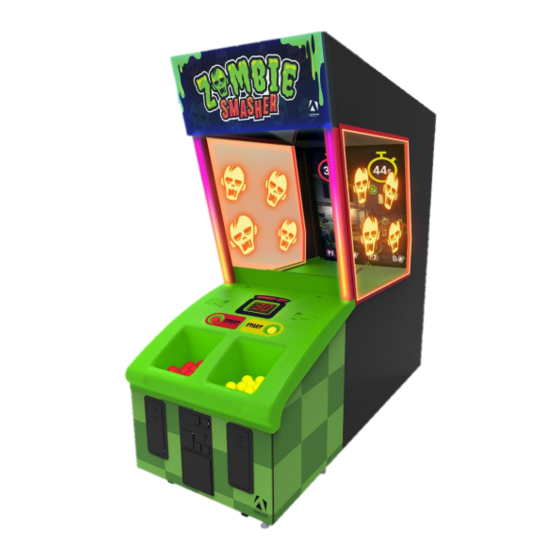
Zombie Smasher Manual V1.0 Chapter 04 – Unit Installation Chapter 03 – Unit Features Hardware Features • 2 Players Game • 65 inches LCD Screen • Unique Ball Trajectory through screen Technology Cabinet Facts Cabinet Dimensions Depth = 108.77” [2762.76mm] Width = 42.71”... -
Page 9: Chapter 04 - Unit Installation
Zombie Smasher Manual V1.0 Chapter 04 – Unit Installation Chapter 04 – Unit Installation Assembling your Zombie Smasher Mechanical Parts Lift and straighten the screen assembly Secure the screen into a lifted position using #10-24 x 1¼ philipps bolts. Repeat for the opposite side... - Page 10 Zombie Smasher Manual V1.0 Chapter 04 – Unit Installation Remove fasteners from the screen support and remove the support assembly Repeat for the opposite side Install lateral posts and secure the window assembly with #10-24 x 1¼ philips bolts Repeat for the opposite side...
- Page 11 Zombie Smasher Manual V1.0 Chapter 04 – Unit Installation Install the window assembly using Philipps pan ¾-8 screws Repeat for the opposite side Install the side panels 1) First, install the bolts window assembly with Philipps pan #8 x ¾ screws 2) Then, install the screen assembly with Phillips pan 10-24 x 1¼...
- Page 12 Zombie Smasher Manual V1.0 Chapter 04 – Unit Installation Install upper side panels 1) Secure the metal brackets with Philipps pan 10-24 x 1¼ bolts 2) secure the window assembly with Philipps pan #8-¾ screws. Repeat for the opposite side Install the lower bolts for the window assembly Repeat for the opposite side.
- Page 13 Zombie Smasher Manual V1.0 Chapter 04 – Unit Installation Install the header assembly with the upper side panels and Philipps 10-24 x 1¼ bolts Repeat for the opposite side Install the ceiling light platform by sliding it from the back of the machine...
-
Page 14: Electronic Parts
Zombie Smasher Manual V1.0 Chapter 04 – Unit Installation Electronic parts 11) R/H: Plug the 2 power cables into their inputs and the LED Controllers together 12) L/H: Plug the 3 power cables into their inputs and the LED Controllers together... - Page 15 Zombie Smasher Manual V1.0 Chapter 04 – Unit Installation 13) Connect the 2 ends of the speaker’s connector 14) Connect the 2 ends of the ground wire connector 15) Connect the USB cable from the dash assembly to the USB hub...
-
Page 16: Closing And Opening The Cabinet
Zombie Smasher Manual V1.0 Chapter 04 – Unit Installation Closing and opening the cabinet 1) Make sure all 4 draw latches are aligned 2) Use the large Allen key to open or close the cabinet 1) Draw latches to be aligned while assembling the two assemblies... -
Page 17: Chapter 05 - Operator Menu
Zombie Smasher Manual V1.0 Chapter 05 – Operator Menu Chapter 05 – Operator Menu Operator Menu Access the Operator Menu by pressing the white operator menu button on inside the dash behind the middle door Navigate through the menu using the 2 main dash buttons as shown on the screen capture below. - Page 18 Zombie Smasher Manual V1.0 Chapter 05 – Operator Menu Operator Menu Values What It Does Game Audio Volume 0-20 Adjusts the in-game audio volume. “0” will mute the game. Attract Audio Volume 0-20 Adjusts the audio volume of the attract loop. “0” will mute the attract loop.
- Page 19 Zombie Smasher Manual V1.0 Chapter 05 – Operator Menu Bonus Paytable If the Bonus Wheel is turned off, the bonus prize will be the highest value If the Bonus Wheel is turned on, a spinning wheel will appear at the beginning of the bonus round. The random result will be the bonus prize (see tables below).
-
Page 20: Chapter 06 - Service & Repair
Zombie Smasher Manual V1.0 Chapter 06 – Service & Repair Chapter 06 – Service & Repair Computer Connections Description USB Port to Windows License Dongle USB Port to Camera USB Port to USB Hub Inlet Power Button AC Inlet Power Supply AC Power Switch Blue Audio Jack 3.5 mm for Top Speakers... -
Page 21: Troubleshooting
Zombie Smasher Manual V1.0 Chapter 06 – Service & Repair Troubleshooting * NOTE: When requesting a warranty replacement, you will be asked to give the unit’s serial number from the back of the unit. Video Troubleshooting There might have loose or faulty connections between the monitor and the computer. -
Page 22: Rgb Led Troubleshooting
Zombie Smasher Manual V1.0 Chapter 06 – Service & Repair RGB Led Troubleshooting If the RGB LEDs are not working properly verify that the RGB LED Controller is connected on a valid COM Port. Press the Operator Button and Quit/Exit the game to Windows Desktop. - Page 23 Zombie Smasher Manual V1.0 Chapter 06 – Service & Repair Expand the “Ports (COM & LPT)” line by clicking on the >. Verify that the “USB Serial Device” is set between COM2 to COM9.
- Page 24 Zombie Smasher Manual V1.0 Chapter 06 – Service & Repair If it’s outside this range, double-click on it to open its properties. Select the “Port Settings” Tab. Click on “Advanced…”...
- Page 25 Zombie Smasher Manual V1.0 Chapter 06 – Service & Repair Click on the COM Port Number scrolling menu and select COM9. Click on OK. Click on OK again. Close the Device Manager window and restart Windows.
-
Page 26: Replacing Rgb Led Pcbs
Zombie Smasher Manual V1.0 Chapter 06 – Service & Repair Replacing RGB LED PCBs If you need to replace the building RGB LED PCBs, verify the connections so that the arrows point always in the same direction. -
Page 27: Wireless Internet Configuration
If not, here’s how to configure your wireless network with your own existing Wi-Fi network. -Start the unit. -There will be Adrenaline Amusements wallpaper with a 150 seconds delay before the attract mode shows up. It gives enough time for a wireless network to connect. -
Page 28: Operator Settings Keeps Resetting
Zombie Smasher Manual V1.0 Chapter 06 – Service & Repair Operator Settings keeps resetting Operator Settings keeps resetting back to default values after powering off the breakers. The Windows & SSD Device write cache needs to be disabled: -Exit the game to Windows. -
Page 29: Computer Not Powering At Boot
Zombie Smasher Manual V1.0 Chapter 06 – Service & Repair Computer not powering at boot If your computer is not powering on by itself at boot you’ll need to verify the Bios Setting. -Power off the computer. -Plug a USB keyboard and a USB mouse. - Page 30 Zombie Smasher Manual V1.0 Chapter 06 – Service & Repair -Click on Advanced tab and then click on Chipset Configuration. -Go to the bottom of that page, click/select the line Restore AC Power Loss , click on the drop box where...
- Page 31 Zombie Smasher Manual V1.0 Chapter 06 – Service & Repair -On your keyboard press on and then click on OK to confirm and save the settings. Or go to the Exit tab, click save and Exit.
-
Page 32: Chapter 07 - Parts
Zombie Smasher Manual V1.0 Chapter 07 – Parts Chapter 07 - Parts Cabinet Parts Part Description Part Number Ceiling Light Platform BLX-02-1010 Header Assembly BLX-08-5000 Ball Receiver BLX-08-2000 Thermoformed Dash BLX-08-1001 Red Large Button with microswitch /LED ADR-75-L012-600 Yellow Large Button with microswitch /LED... - Page 33 Zombie Smasher Manual V1.0 Chapter 07 – Parts Window Assemblies Part Description Part Number BLX-01-1007 BLX-01-1040 BLX-08-1005 Printed Plexiglass, Left Side, Zombie Smasher ZS-08-1002-L Printed Plexiglass, Right Side, Zombie Smasher ZS-08-1002-R BLX-01-1043 BLX-01-1005 BLX-01-1042 BLX-02-8000-01 BLX-08-1006 BLX-02-8000-02 BLX-08-1007 BLX-08-1008 BLX-08-1010...
-
Page 34: Computer & Electronics
Sound Amplifiers +5V/300W Power Supply SF-14-0010 RGB LEDs Controller INV-14-1030 PC Box for Zombie Smasher ADR-11-1018 7-Ports USB Hub Powered INV-11-1021 Restore USB Key Zombie Smasher for H370 ADR-11-2014-ZS-H370 Hard Drive for Zombie Smasher for H370 INV-11-1027-ZS-H370 Yellow Dongle TF-04-1212... -
Page 35: Header & Leds
Fastening Latches Red Ball, Zombie Smasher BLX-05-0001 Yellow Ball, Zombie Smasher BLX-05-0002 Other Electronic Parts Part Description Part Number PCB For Step Motor Drive, Zombie Smasher BLX-04-0002 PCB For Color Sensor, Zombie Smasher BLX-04-0003 Pcb Kit Including 2 Digits Display BLX-04-0004-Kit... - Page 36 Zombie Smasher Manual V1.0 Chapter 07 – Parts Cabinet Doors Part Description Part Number Ticket Dispenser Door Including LEDs, Without Dispenser ADR-40-0540-00KA Door and Frame Assembly with Blank Upper and Bottom Door ADR-40-0745-20KA Door Assembly With 2 Upper Mech Holder,...
- Page 37 Zombie Smasher Manual V1.0 Chapter 07 – Parts Front Wood Module Part Description Part Number Printed Center Melamine for Zombie Smasher BLX-02-0002-01 Printed Right Melamine for Zombie Smasher BLX-02-0002-02 Printed Left Melamine for Zombie Smasher BLX-02-0002-03 Dash Wood Melamine ¾ item 4 BLX-02-0002-04 Dash Wood Melamine ¾...
- Page 38 Zombie Smasher Manual V1.0 Chapter 07 – Parts Rear Wood Module Part Description Part Number Rear Wood Melamine ¾ item 1 BLX-02-2000-01 Rear Wood Melamine ¾ item 2 BLX-02-2000-02 Rear Wood Melamine ¾ item 3 BLX-02-2000-03 Rear Wood Melamine ¾ item 4 BLX-02-2000-04 Rear Wood Melamine ¾...
- Page 39 Zombie Smasher Manual V1.0 Chapter 07 – Parts Ball Distribution System Part Description Part Number Step Motor NEMA 23 BLX-05-0004 Step Motor Bracket BLX-01-3012 Set Screw Flexible Shaft Coupling, 1-23/32" Long, INV-6408K11 1-5/64" OD, For 10mm Diameter Rubber Spider For 1-5/64" OD...
- Page 40 Zombie Smasher Manual V1.0 Chapter 07 – Parts Ball Gate Assembly Part Description Part Number Kit for Motor 12V and Harness Assembly INV-15-0005-KIT Gate Motor Bracket BLX-01-3011 Mounting Hub, Aluminum, 6mm (4-40) INV-RB-POL-136 Aluminum Gate Cam 1/8'' BLX-01-1032 Ball Joint Rod End, 1/4''-28 Thread...
- Page 41 Zombie Smasher Manual V1.0 Chapter 07 – Parts Ball Selection System Part Description Part Number Rotary Solenoid BLX-05-0003 Direction Plate BLX-01-3005 Red Rubber Tubing, 1/4" ID, 1/2" OD, 2'' INV-5543K62 Shoulder Screw, 1'' x 1/4", 10-24 SS-HSO-AS-1/4X10-24X1 Mounting Hub, Aluminum, 8mm (M3)
- Page 42 Zombie Smasher Manual V1.0 Chapter 07 – Parts Header & LEDs Part Description Part Number Zombie Smasher Header ZS-08-5000 Top Display Bracket BLX-01-1021 Monitor Replacement Parts Part Description Part # Monitors 65'', Black Frame, With Safety Glass RAM-10-0001 Video Board for 65 Monitor RAM-10-0001-VIDEO-BOARD Inverter Backlight Board with Cable and Harness for 65’’...
-
Page 43: Cabling
USB Cable 2.0 'AB', White, 3' INV-USB-AB1-03 INV-USB-AB1-10BK Cable 2.0 'AB', Black, 10', TFX Barrel Power Cable, Male-Female, 4', Zombie BLX-03-0023 Smasher Main Power Cable, Zombie Smasher BLX-03-0027 Misc. Parts Part Description Part Number Power Entry EMI Filter ADR-05-1241 Windows 10 Licence... -
Page 44: Wiring Harness
Zombie Smasher Manual V1.0 Chapter 07 – Parts Wiring Harness Part Description Part Number Connector for LEDs Spinner SF-05-0014 Barrel Connector Wire ''Y'', 2.1mm Female to 2 x TF-05-1223 2.1mm Male, 300mm, LED Header, Fruit Ninja Harness IO Board to Buttons... -
Page 45: Chapter 08 - Diagrams & Schematics
Zombie Smasher Manual V1.0 Chapter 08 – Diagrams & Schematics Chapter 08 – Diagrams & Schematics I/0 Board ADR-04-1003... - Page 46 Zombie Smasher Manual V1.0 Chapter 08 – Diagrams & Schematics Display Keypad No Use No Use 1. (White) TD+ 1. (Red) Operator 2. (Blue) TD- 2. Not Connected 3. (Red) 5V 3. Not Connected 4. (Black) GND 4. Not Connected 5.
-
Page 47: I/O Board - Detailed Wiring
Zombie Smasher Manual V1.0 Chapter 08 – Diagrams & Schematics I/O Board – Detailed Wiring... - Page 48 Zombie Smasher Manual V1.0 Chapter 08 – Diagrams & Schematics...
-
Page 49: Tickets Wiring
Zombie Smasher Manual V1.0 Chapter 08 – Diagrams & Schematics Tickets Wiring Operator Menu Button Wiring... -
Page 50: Speakers Wiring Colors
Zombie Smasher Manual V1.0 Chapter 08 – Diagrams & Schematics Speakers Wiring Colors Speaker Player 4 Speaker Dash Player 3 Speaker Dash Speaker... -
Page 51: Power Distribution Schematics
Zombie Smasher Manual V1.0 Chapter 08 – Diagrams & Schematics Power Distribution Schematics Page 51 of 60... - Page 52 Zombie Smasher Manual V1.0 Chapter 08 – Diagrams & Schematics Page 52 of 60...
-
Page 53: Tray Assembly Schematics
Zombie Smasher Manual V1.0 Chapter 08 – Diagrams & Schematics Tray Assembly Schematics Page 53 of 60... -
Page 54: Fuse Holders Schematics
Zombie Smasher Manual V1.0 Chapter 08 – Diagrams & Schematics Fuse Holders Schematics Page 54 of 60... -
Page 55: Rgb Led Schematics
Zombie Smasher Manual V1.0 Chapter 08 – Diagrams & Schematics RGB LED Schematics Each side has 2 strips of RGB PCB LED assembly Each strip has 100 LEDs BLX-14-0001 Page 55 of 60... -
Page 56: Channel 1
Zombie Smasher Manual V1.0 Chapter 08 – Diagrams & Schematics Channel 1 Page 56 of 60... -
Page 57: Channel 2
Zombie Smasher Manual V1.0 Chapter 08 – Diagrams & Schematics Channel 2 Page 57 of 60... -
Page 58: Chapter 09 - Software Recovery
Zombie Smasher Manual V1.0 Chapter 09 – Software Recovery Chapter 09 – Software Recovery If your unit’s software needs to be restored, please follow those instructions. Connect a USB keyboard to the motherboard. Connect the provided USB Recovery flash disk is in a Blue USB port. -
Page 59: Chapter 10 - Card Reader
Configure your Operator settings as seen in Chapter 5 - Operator Menu. Embed System If you are using an Embed system, you need to connect your harnesses to Adrenaline Amusements I/O board & harnesses. You should refer to the Embed instructions manual for wiring pin-out. -
Page 60: Limited Warranty Policies
This unit has 1-year warranty against defective hardware from date of delivery. Other than abuse or improper servicing, Adrenaline Amusements covers at no charge the replacement parts including standard shipping. We offer an advanced replacement program and the customers have 30 days from delivery date to return back the defective equipment at their fees or they will be charged automatically for the replacement parts.
Need help?
Do you have a question about the Zombie Smasher and is the answer not in the manual?
Questions and answers