
Related Manuals for Adrenaline Tomb Raider


Summary of Contents for Adrenaline Tomb Raider
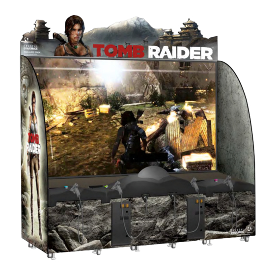
- Page 1 Tomb Raider TR-120-1001 Operation & Service Manual Version 5.0 * Read this manual before use...
-
Page 2: General Remark
General Remark If you encounter any difficulties or if you need support on how to update and/ or install your Tomb Raider product, we invite you to contact your local distributor or reach us at support@aagames.com or by calling our support line +1-450-824-1671... -
Page 3: Table Of Contents
Hardware Features ........................8 Cabinet Facts ..........................8 Chapter 03 – Unit Installation ................9 Parts included ..........................9 Assembling your Tomb Raider Unit ..................10 Cabinet & Side Panels Assembly ....................11 Screen Assembly ........................16 Header Assembly ........................19 Chapter 04 –... - Page 4 Tomb Raider Manual V5.0 Video Troubleshooting ........................37 Audio Troubleshooting ........................37 Wireless Internet Configuration ....................38 Operator Settings keeps resetting trouble ................39 Computer not powering at boot ....................40 Chapter 06 - Parts ..................... 41 Cabinet Parts ..........................41 Computer &...
-
Page 5: Chapter 01 - Preface
Tomb Raider Manual V5.0 Chapter 01 - Preface Chapter 01 - Preface Please read this page before preparing your Tomb Raider Arcade product for game play. The following safety instructions apply to all game operators and service personnel. Specific warnings and cautions will be included throughout this manual. -
Page 6: Safety
If a power cord is damaged, it must be replaced by the equivalent power cord available from your distributor. Adrenaline Amusement Inc. assumes no liability for any damages or injuries incurred while setting up or servicing the cabinet. Only qualified service personnel should perform installation or service procedures. -
Page 7: Maintenance Warning
Tomb Raider Manual V5.0 Chapter 01 - Preface Maintenance Warning You should be very careful when touching the screen material as it is relatively easy to scratch. If the screen is dusty, use a feather duster. If this is not enough use a damp cloth and wipe carefully sideways following the direction of the lens structure. -
Page 8: Chapter 02 - Unit Features
Tomb Raider Manual V5.0 Chapter 02 – Unit Features Chapter 02 – Unit Features Hardware Features • 4 Players Game • 120 inches Screen • Unique Sensor Tracker “Gun” Technology! Cabinet Facts Cabinet Dimensions Depth = 40.35” [1024.89mm] Width = 109.00” [2768.60mm] Shipping Dimensions Width = 44”... -
Page 9: Chapter 03 - Unit Installation
1x Center Cabinet 1x Right Cabinet 1x Left Side Panel 1x Right Side Panel 1x “Lara” Header part 1x “Tomb Raider” Header part 1x “Mountain” Header part 1x Left tablet with splitter power cable 1x Right tablet 1x Large Metal Angle Plate... -
Page 10: Assembling Your Tomb Raider Unit
Tomb Raider Manual V5.0 Chapter 03 – Unit Installation Assembling your Tomb Raider Unit **You need to be 3 persons to assemble the unit** 1. Carefully remove the cabinets from the shipping skids, giving you enough space. 2. Move the 3 cabinets and the side panels to the desired location. -
Page 11: Cabinet & Side Panels Assembly
Tomb Raider Manual V5.0 Chapter 03 – Unit Installation Cabinet & Side Panels Assembly 3. Assemble the cabinet together using the provided 10X Bolts Allen button head #10-24 x 1-½” & washers. 5x Bolts per sides. The bolts need to be inserted from the center cabinet towards the exterior ones. - Page 12 Tomb Raider Manual V5.0 Chapter 03 – Unit Installation 4. Under the cabinets, locate and install the provided 2x Allen button Head Bolts ¼-20 x ¾” with the washers ¼” to hold and secure the cabinets together. 5. Lower the Level adjustors until the Pivot Wheels are slightly above the floor.
- Page 13 Tomb Raider Manual V5.0 Chapter 03 – Unit Installation 6. The illuminated “Lara Croft” is the exterior side of the unit. -Take the power cable from the side panel and guide it through the hole on the side cabinet. -Slowly get the side panel closer to the cabinet while watching to avoid squeezing the cable.
- Page 14 Tomb Raider Manual V5.0 Chapter 03 – Unit Installation 7. Install the side panel to the cabinet by using the Black Allen Button Head Bolts #10-24 x 1½” and Black Washers #10. Each side panels needs 6 bolts. 8. Install the metal angle on each panel with Black Phillips Screws #8 x ¾”.
- Page 15 Tomb Raider Manual V5.0 Chapter 03 – Unit Installation 9. Connect the 5 harnesses between the edge cabinets to the center cabinet together. 15 | P a g e...
-
Page 16: Screen Assembly
Tomb Raider Manual V5.0 Chapter 03 – Unit Installation You should be very careful when touching the screen material as it is relatively easy to scratch. If the screen is dusty, use a feather duster. If this is not enough use a damp cloth and wipe carefully sideways following the direction of the lens structure. - Page 17 Tomb Raider Manual V5.0 Chapter 03 – Unit Installation 11. Using the #10-24 x 1½” Allen Head Buttons Bolts & Washers #10 (3 on each sides), affix the screen to the side panels of the cabinet. 17 | P a g e...
- Page 18 Tomb Raider Manual V5.0 Chapter 03 – Unit Installation 12. Secure the metal bottom plate of the screen to the cabinet by using the 7x black Philips screws #8 x ¾”. 13. The +12V Barrel Power Cable behind the cabinet will be for the header LEDs power. Leave it attached for now we will use it later.
-
Page 19: Header Assembly
Tomb Raider Manual V5.0 Chapter 03 – Unit Installation Header Assembly 19 | P a g e... - Page 20 Tomb Raider Manual V5.0 Chapter 03 – Unit Installation 14. Parts Needed: “Right Side” piece of wood, the large metal square, the small metal square, 2x Carriage Bolts #10-24 x 1½” and 2x K-Lock Nuts #10-24. - Install the longer side of the larger metal square bracket on a flat surface, the smaller side will be vertical and near you.
- Page 21 Tomb Raider Manual V5.0 Chapter 03 – Unit Installation 15. Parts needed: “Left Side” Piece of wood, 2x Carriage Bolts #10-24 x 1½” and 2x K-Lock Nuts #10-24. - Slide the 2 piece of wood between the metal square brackets.
- Page 22 Tomb Raider Manual V5.0 Chapter 03 – Unit Installation 2 ladders and minimum 2 persons needed. Go behind the unit, one person on each side. Install the header platform assembly on the side panel’s brackets and the screen as followed.
- Page 23 Tomb Raider Manual V5.0 Chapter 03 – Unit Installation 17. Using 8x Black Wood Philips Screws #8 x ¾”, align and install the metal square bracket to the back of the screen assembly. 23 | P a g e...
- Page 24 Tomb Raider Manual V5.0 Chapter 03 – Unit Installation 18. Using 4x Black Wood Philips Screws #8 x ¾”, secure the metal square brackets to the header platform assembly. 24 | P a g e...
- Page 25 Tomb Raider Manual V5.0 Chapter 03 – Unit Installation 19. Take the “Tomb Raider” Plexiglas part and remove the film protection. - Install the small metal square 2½” x 2½” x 5/8” to the acrylic with 2x screws zinc #6 x 3/8”.
- Page 26 - Install the small metal square 2½” x 2½” x 5/8” to the acrylic with 2x screws zinc #6 x 3/8”. - Insert it in the groove next to the “Tomb Raider” section as seen below. - Using the Black Wood Philips Screws #8 x ¾”, secure the Plexiglas to the assembly through the small metal square bracket 2½”...
- Page 27 Tomb Raider Manual V5.0 Chapter 03 – Unit Installation 21. Install the Mountains cardboard into the groove as seen below. 22. Insert the metal flat bars through the holes of the cardboard and using the Black Wood Philips Screws #8 x ¾” secure the cardboard to the assembly.
- Page 28 Tomb Raider Manual V5.0 Chapter 03 – Unit Installation 23. Connect the 12V Barrel connector with the one coming from the cabinet. Use tape to stick it behind the screen assembly and avoiding a loose cable. 28 | P a g e...
-
Page 29: Chapter 04 - Operator Menu
Tomb Raider Manual V5.0 Chapter 04 – Operator Menu Chapter 04 – Operator Menu Operator Menu Access the Operator Menu by pressing the Operator button located inside the drawer on the I/O board directly. Oper: Open the Operator Menu Up: Scroll Up & Increase Value Down: Scroll Down &... - Page 30 Tomb Raider Manual V5.0 Chapter 04 – Operator Menu Operator Menu Values What It Does Credits Per Game 1-20 Adjusts the number of credits required to play. “0” sets the unit in free play mode Game Audio Volume 0-20 Adjusts the in-game audio volume. “0” will mute the...
-
Page 31: Chapter 05 - Service & Repair
Tomb Raider Manual V5.0 Chapter 05 – Service & repair Chapter 05 – Service & Repair Computer Connections Description HDMI Cable to Projector HDMI-1 Connector Audio Jack to Amplifier #1 Audio Jack to Amplifier #2 USB Wi-Fi Adapter USB Restore Flash Drive... -
Page 32: Projector Connections
Tomb Raider Manual V5.0 Chapter 05 – Service & repair Projector Connections 32 | P a g e... -
Page 33: Projector Settings
Tomb Raider Manual V5.0 Chapter 05 – Service & repair Projector Settings Recommended Projector Picture Settings Here are new recommended settings to improve the screen display from the projector. To adjust the projector settings, open the center cabinet service door and use the remote control. - Page 34 Tomb Raider Manual V5.0 Chapter 05 – Service & repair To adjust the focus, use the Focus Adjustment Switch on the right of the projector. 34 | P a g e...
-
Page 35: Gun Controller Id Remapping
Tomb Raider Manual V5.0 Chapter 05 – Service & repair Gun Controller ID Remapping Each gun controller has an ID # to be identified as Player 1 to Player 4. If a Stem Stick is replaced and/or has a wrong ID, it needs to be remapped. If a gun controller is not detected in the game, first verify within the Operator menu “Gun Tool”... - Page 36 Tomb Raider Manual V5.0 Chapter 05 – Service & repair To remap an ID, double click with the mouse to select the good Stem Stick ID. Click in the “Change ID (1-4)” box with your mouse and enter the good ID number (1 to 4) that matches the player position.
-
Page 37: Troubleshooting
Tomb Raider Manual V5.0 Chapter 05 – Service & repair Troubleshooting * NOTE: When requesting a warranty replacement you will be asked to give the unit’s serial number from the back of the unit. Video Troubleshooting There could be loose or faulty connections between the projector and the computer. -
Page 38: Wireless Internet Configuration
If not, here’s how to configure your wireless network with your own existing Wi-Fi network. -Start the unit. -There will be Adrenaline Amusements wallpaper with a 150 seconds delay before the attract mode shows up. It gives enough time for a wireless network to connect. -
Page 39: Operator Settings Keeps Resetting Trouble
Tomb Raider Manual V5.0 Chapter 05 – Service & repair Operator Settings keeps resetting trouble Operator Settings keeps resetting back to default values after powering off the breakers. The Windows & SSD Device write cache needs to be disabled: -Exit the game to Windows. -
Page 40: Computer Not Powering At Boot
Tomb Raider Manual V5.0 Chapter 05 – Service & repair Computer not powering at boot If your computer is not powering on by itself at boot verify the Bios Setting. -Power off the unit. -Plug a USB keyboard. -Power on the unit, press and hold “DELETE” on the keyboard until you see the Bios screen. -
Page 41: Chapter 06 - Parts
Tomb Raider Manual V5.0 Chapter 06 – Parts Chapter 06 - Parts Cabinet Parts 41 | P a g e... - Page 42 Tomb Raider Manual V5.0 Chapter 06 – Parts Part Description Part # Complete Screen Assembly RHW-10-0006 Printed Laminated Left Side Panel TR-09-0004-L-Kit Printed Laminated Right Side Panel TR-09-0004-R-Kit Thermoformed Left/Right Console (No TR-07-0002 buttons) Thermoformed Center Console /with Glass TR-06-0001 /with Buttons Green &...
-
Page 43: Computer & Electronics
Tomb Raider Manual V5.0 Chapter 06 – Parts Computer & Electronics Part Description Part Number Power Bar IEC5GLM INV-05-1242 I/O Board – 4 Players/Motors – Ver. 5.0 ADR-04-1003-RHW Sound Amplifier 2X15W INV-14-0005 +12V / 320W Power Supply INV-05-1248 +12V / 5A Power Supply for... - Page 44 Gun Assembly /w Hose – Player 2 TR-05-0011-2 Gun Assembly /w Hose – Player 3 TR-05-0011-3 Gun Assembly /w Hose – Player 4 TR-05-0011-4 Part Description Part Number Hose Kit for Tomb Raider 120’’ RHW-96-1047-30SH-TR-KIT Part Description Part Number Trigger Switch ADR-95-4142-10 Compression Spring (Reload) TR-05-0001...
- Page 45 Tomb Raider Manual V5.0 Chapter 06 – Parts Part Description Part Number Quantity 1 Compression Spring (Reload) TR-05-0001 2 Black Trigger ADR-96-2515-06 3 Vibration Motor 34mm INV-15-0006 4 Trigger Return Spring ADR-96-0005-00 5 Hex Drive Rounded Head Screw INV-92095A471 6 Trigger Switch / Reload switch...
- Page 46 Tomb Raider Manual V5.0 Chapter 06 – Parts Part Description Part Number Sphere White Coil 90mm INV-05-1246 Stem Controller Base Board INV-04-1301-01 +15V 40W Base Power Supply INV-05-1245 Ultra Short Throw Projector RHW-10-0001 46 | P a g e...
-
Page 47: Header & Leds
Tomb Raider Manual V5.0 Chapter 06 – Parts Header & LEDs Part Description Part Number “Lara Croft” Header 48” x 24” TR-09-0001-Kit “Tomb Raider” Header 48” x 24” TR-09-0002-Kit “Mountain” Header 48” x 96” TR-09-0003-Kit 47 | P a g e... -
Page 48: Cabling
Tomb Raider Manual V5.0 Chapter 06 – Parts Cabling Part Description Part Number HDMI Cable, 3’ INV-HDMI-140-03UT USB “AB” cable, 3’ INV-USB-AB1-03 USB A Male to Mini-B 5-pins male, 6’ INV-USB-AM51-06 Extension USB A Male to USB A Female, 6’... -
Page 49: Wiring Harness
Tomb Raider Manual V5.0 Chapter 06 – Parts Wiring Harness Part Description Part Number Harness for Speakers Player 1 & 4 (Center) RHW-03-0001 Harness for Speakers Player 1 & 4 RHW-03-0002 (Left & Right Side) Harness for Speakers Player 2 &3... -
Page 50: Chapter 07 - Diagrams & Schematics
Tomb Raider Manual V5.0 Chapter 07 – Diagrams & Schematics Chapter 07 – Diagrams & Schematics I/0 Board ADR-04-1003 50 | P a g e... - Page 51 Tomb Raider Manual V5.0 Chapter 07 – Diagrams & Schematics No Use No Use No Use No Use MOTOR 5V No Use No Use No Use 1. (Red) +5V 2. (Black) GND 3. (Red) +5V 4. (Black) GND 5. (Red) +5V 6.
-
Page 52: I/O Board - Wiring
Tomb Raider Manual V5.0 Chapter 07 – Diagrams & Schematics I/O Board - Wiring 52 | P a g e... - Page 53 Tomb Raider Manual V5.0 Chapter 07 – Diagrams & Schematics 53 | P a g e...
- Page 54 Tomb Raider Manual V5.0 Chapter 07 – Diagrams & Schematics 54 | P a g e...
- Page 55 Tomb Raider Manual V5.0 Chapter 07 – Diagrams & Schematics 55 | P a g e...
- Page 56 Tomb Raider Manual V5.0 Chapter 07 – Diagrams & Schematics 56 | P a g e...
- Page 57 Tomb Raider Manual V5.0 Chapter 07 – Diagrams & Schematics Speakers Wiring Colors 57 | P a g e...
-
Page 58: Power Distribution Schematics
Tomb Raider Manual V5.0 Chapter 07 – Diagrams & Schematics Power Distribution Schematics 58 | P a g e... - Page 59 Tomb Raider Manual V5.0 Chapter 07 – Diagrams & Schematics 59 | P a g e...
-
Page 60: Chapter 08 - Software Recovery
Tomb Raider Manual V5.0 Chapter 08 – Software Recovery Chapter 08 – Software Recovery If your unit software needs to be restored please follow those instructions. Connect a USB keyboard to the motherboard. Connect the provided USB Recovery flash disk is in a Black USB port. -
Page 61: Chapter 09 - Card Reader
Configure your Operator settings as seen in Chapter 04. Embed System If you are using an Embed system, you need to connect your harnesses to Adrenaline Amusements I/O board & harnesses. You should refer to the Embed instructions manual for wiring pin-out. -
Page 62: Limited Warranty Policies
Improper servicing or abuse will VOID existing warranties. All warranty request needs to be validated with our technical support department. After the 1 year warranty, Adrenaline Amusements offers repairs & sales services options. Please contact the technical support department for information.
Need help?
Do you have a question about the Tomb Raider and is the answer not in the manual?
Questions and answers