Table of Contents
Advertisement
Quick Links
ORing Industrial Networking Corp.
GIGABIT
SWITCH
Q
I
uick
nstallation
I N D U S T R I A L
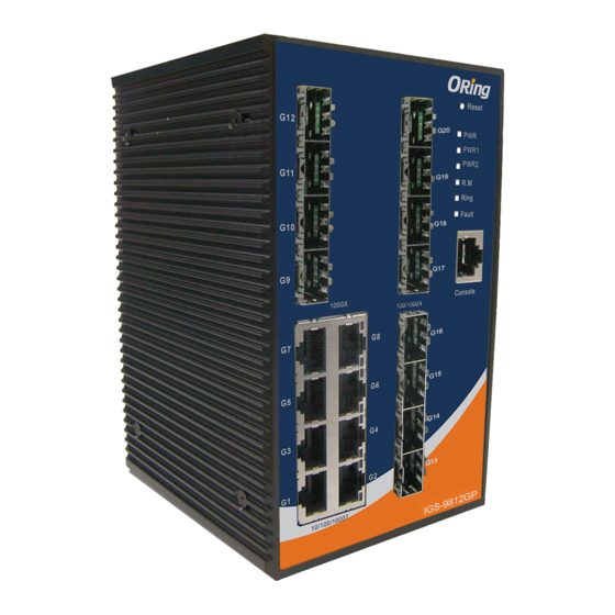
Introduction
The
IGS-9844/9848GPFX series
are managed Ethernet switches with
8x10/100/1000Base-T(X) ports, 4x100/1000Base-X SFP ports, and 4
9844 GPFX series)
or 8
(IGS-9848GPFX series)
ports with SC connectors.
Package Contents
The
IGS-9844/9848GPFX series
are shipped with the following items. If any
of these items is missing or damaged, please contact your customer service
representative for assistance.
Contents
Pictures
Number
IGS-9844GPFX
IGS-9848GPFX
CD
DIN-rail Kit
Wall-mount Kit
Console Cable
QIG
Preparation
Before you begin installing the switch, make sure you have all of the package
contents available and a PC with Microsoft Internet Explorer 6.0 or later, for
using web-based system management tools.
Safety & Warnings
Elevated Operating Ambient:
If installed in a closed or multi-unit rack
assembly, the operating ambient temperature of the rack environment may be
greater than room ambient. Therefore, consideration should be given to
installing the equipment in an environment compatible with the maximum
ambient temperature (Tma) specified by the manufacturer.
Reduced Air Flow:
Installation of the equipment in a rack should be such
that the amount of air flow required for safe operation of the equipment is
not compromised.
Mechanical Loading:
Mounting of the equipment in the rack should be
such that a hazardous condition is not achieved due to uneven mechanical
loading.
Circuit Overloading:
Consideration should be given to the connection of the
equipment to the supply circuit and the effect that overloading of the circuits
might have on overcurrent protection and supply wiring. Appropriate
consideration of equipment nameplate ratings should be used when addressing
this concern.
Q I G
IGS-9844/9848GPFX Series
IGS-9844/9848GPFX Series
G
uide
Dimension
(IGS-
96.4
100Base-X optical fiber
70.5
15.0
10.9
G12
PWR
P16
PWR1
PWR2
G11
LNK/ACT
G10
G9
P15
100/1000X
G8
G7
P14
G6
G5
LNK/ACT
G4
G3
P13
G2
G1
10/100/1000T
100FX
IGS-9844GPFX
Number
X 1
96.4
70.5
15.0
10.9
X 1
G12
PWR
P16
P20
PWR1
PWR2
G11
LNK/
ACT
G10
X 1
X 1
G9
P15
P19
100/1000X
G8
G7
P14
P18
G6
G5
LNK/
ACT
X 1
X 1
G4
G3
P13
P17
G2
G1
10/100/1000T
100FX
IGS-9848GPFX
X 2
X 2
Panel Layouts
X 1
X 1
Front View
X 1
X 1
G12
G11
1
G10
G9
100/1000X
G8
G7
G6
G5
2
G4
G3
G2
G1
10/100/1000T
IGS-9844GPFX
Rear View
1
1
1907-2-29-IGS984XGPFX-1.0
30.0
87.0
58.0
48.0
105.5
IGS-9844GPFX
30.0
87.0
58.0
48.0
105.5
IGS-9848GPFX
1. SFP fiber ports
G12
3
PWR
3
PWR
P16
P16
P20
2. RJ45 ports
4
PWR1
4
PWR1
PWR2
PWR2
5
5
G11
3. Power LED
6
6
1
LNK/
LNK/ACT
7
7
ACT
4. PWR1 LED
8
G10
8
5. PWR2 LED
9
9
P15
P15
P19
G9
6. R.M. status LED
100/1000X
7. Ring status LED
10
10
G8
G7
8. Faulty relay indicator
P14
P14
P18
9. Console port
G6
G5
10. Fiber ports
2
LNK/
LNK/ACT
ACT
G4
G3
P13
P13
P17
G2
G1
10/100/1000T
100FX
100FX
IGS-9844GPFX
IGS-9848GPFX
IGS-9848GPFX
1. Wall-mount screw holes
1. Wall-mount screw holes
2. Din-rail screw holes
2. Din-rail screw holes
2
ORing Industrial Networking Corp.
Copyright© 2013 ORing
All rights reserved.
TEL: +886-2-2218-1066
Website: www.oring-networking.com
FAX: +886-2-2218-1014
E-mail: support@oring-networking.com
PRINTED ON RECYCLED PAPER
Industrial Managed Gigabit Switch
Top Panel
R2.5
PWR-2
Fault
PWR-1
1
1A@24V
1. Terminal blocks: PWR1, PWR2
V2- V2+
V1- V1+
DC 48V
(12-48V DC), Relay
2
2. Ground wire.
R3.95
95.9
Installation
DIN-rail Installation
R2.5
Step 1:
Slant the switch and screw the Din-rail kit onto the back of the switch, right in
the middle of the back panel.
Step 2:
Slide the switch onto a DIN-rail from the Din-rail kit and make sure the switch
clicks into the rail firmly.
R3.95
95.9
Wall-mounting
Step 1:
Screw the two pieces of wall-mount kits onto both ends of the rear panel of the
switch. A total of six screws are required, as shown below.
Step 2:
Use the switch, with wall mount plates attached, as a guide to mark the
correct locations of the four screws.
Step 3:
Insert four screw heads through the large parts of the keyhole-shaped apertures,
and then slide the switch downwards. Tighten the four screws for added stability.
Version 1.0
G12
PWR
G16
PWR1
G11
PWR2
LNK/ACT
G10
G9
G15
100/1000X
G8
G7
G14
G6
G5
LNK/ACT
G4
G3
G13
G2
G1
10/100/1000T
1000FX
IGS-9844GPF
Quick Installation Guide
Advertisement
Table of Contents

Related Manuals for ORiNG IGS-9844GPFX Series


Summary of Contents for ORiNG IGS-9844GPFX Series
- Page 1 Version 1.0 ORing Industrial Networking Corp. GIGABIT SWITCH IGS-9844/9848GPFX Series Industrial Managed Gigabit Switch uick nstallation uide I N D U S T R I A L Introduction Dimension IGS-9844/9848GPFX series are managed Ethernet switches with 8x10/100/1000Base-T(X) ports, 4x100/1000Base-X SFP ports, and 4...
- Page 2 Weight (g) 710 g 722 g 735 g 735 g 740 g 740 g using ORing’s Open-Vision management utility, Storage Temperature -40 to 85 C (-40 to 185 F) PIN#5 GND PIN#5 GND PIN#5 GND please go to ORing website.
Need help?
Do you have a question about the IGS-9844GPFX Series and is the answer not in the manual?
Questions and answers