Table of Contents
Advertisement
Quick Links
Advertisement
Table of Contents

Related Manuals for Triton XEROPHYTE


Summary of Contents for Triton XEROPHYTE
- Page 1 WATER-SAVING DIGITAL SHOWER INSTALLATION GUIDE For a cleaner conscience...
- Page 2 The Triton Xerophyte has been designed to incorporate innovative water conservation features, while at the same time delivering outstanding performance for the best possible shower experience.
-
Page 3: Table Of Contents
Plumbing Connections ………………………...…….…. Electrical Connections …………………..………………. Installation Schematic ……………………..……..…….. Xerophyte Control Installation ……………………………………. Data Cable Installation …………………..……..….….… Fixing Bracket Installation ………..……………………… Xerophyte Controller Unit Fitting (Wired) ……………… Xerophyte Controller Unit Fitting (Wireless)………….… Commissioning …………………………………………………….. Quick Start …………………………………………….……………. General Maintenance ……………………………………………… Product Care…..……………………………….……….. -
Page 4: Important Information
Triton Xerophyte Mixer Unit to any form of tap or fitting not recommended by the manufacturer. The Triton Xerophyte Mixer Unit MUST be installed as close as possible to the shower outlet. The length of pipework from the Triton Xerophyte Mixer Unit to the outlet fitting MUST... - Page 5 The Triton Xerophyte must be connected to a residual current device circuit breaker in accordance with current wiring regulations. If the Triton Xerophyte Mixer Unit is to be installed within a bath or shower room the electrical installation MUST conform to SANS 10142-1: 2017 (Edition 2).
-
Page 6: Dimensions
Dimensions Triton Xerophyte Control Unit (Including Wall Fixing Bracket) Professional Installer Notes On premises with metallic surfaces e.g. metal ceiling panels, metal ducting and metallic insulating materials, we recommend wired connection as wireless transmissions MAY BE BLOCKED from the control panel and thus prevent correct operation of... - Page 7 Dimensions CONTROLLER CABLE 220V CONNECTION CONNECTION OUTLETS INLETS COLD SHOWER CIRCULATION OUTLET LOOP OUTLET INLET RECOMMENDED INSTALLATION SPACE COLD REQUIREMENT INLET...
-
Page 8: Xerophyte Mixer Unit
Showering temperature 32°Cto47°C* adjustment range Splash-proof rating IP24 *MaximumTemperature setting can be adjusted between 41°C and 47°C (factory set at 47°C). **The Triton Xerophyte Mixer Shower is supplied with 15mm push-fit connectors, DO NOT use any other type of fitting. -
Page 9: Main Components
4. 15mm push-fit connectors with isolating 11. Circulation loop valves 12. 15mm push-fit straight connector 5. Xerophyte Mixer Unit inlets (HOT & COLD) 13. 15mm push-fit elbow connector 6. Xerophyte Mixer Unit shower outlet 14. 15mm push-fit tee connector 7. Xerophyte Mixer Unit data cable connector... -
Page 10: Installation Information
MUST BE undertaken by a qualified competent person. The Triton Xerophyte Mixer Unit may be installed in a loft space, in a convenient cupboard or in the shower with the Xerophyte Vanity cove (sold separately), provided there is enough room for maintenance. -
Page 11: Typical Suitable Installations
Interference from other wirelessly controlled devices and radio signals can dramatically reduce the ability of the wireless Triton Xerophyte Shower Mixer to maintain a good, consistent wireless signal. This may include mobile phones, cordless phones, radio- controlled toys, wireless doorbells, etc. -
Page 12: High-Pressure Instantaneous Hot Water Systems
Typical Suitable Installations High-Pressure Instantaneous Hot Water System Installation The Triton Xerophyte Mixer Unit MUST be installed with a multipoint on demand gas water heater of a fully modulating design (i.e. where the water draw-off rate indirectly controls the gas flow rate to the burner). - Page 13 On-demand gas heaters are not always able to supply an adequate flow rate of hot water, particularly in winter. Triton recommends fitting a flow regulator (supplied with the shower) into the Hot inlet of the Triton Xerophyte Mixer Unit before installation. Refer to the table for details (see Fig 2).
-
Page 14: High-Pressure Unvented Mains Pressure Cylinders
Typical Suitable Installations High-Pressure Unvented Mains Fig 3 Processor Unit Pressure Cylinder Installation For systems with no cold water take off after the appliance reducing valve, it will Safety devices not shown be necessary to fit an additional drop Circulation Loop tight pressure reducing valve when the mains pressure is over 500kPa (5 bar). -
Page 15: High-Pressure Thermal Store Systems
Typical Suitable Installations High-Pressure Thermal Store Fig 4 Systems Installation The high-pressure system MUST be fitted Mixer Unit with a tempering valve (blender valve). The appliance MUST be capable of raising Circulation loop the temperature of the incoming water to a minimum of 55°C and delivering a flow Hot water rate of not less than 8 L/minute. -
Page 16: Low-Pressure Gravity Fed Systems
IMPORTANT: Pipework layouts and connections MUST be such that other draw-offs will not affect water supplies to the Triton Xerophyte Mixer Unit, shared supplies may lead to air locking or water starvation. It is, therefore, essential to have independent hot and cold supplies to the Triton Xerophyte Mixer Unit. - Page 17 Installations General installation Guidelines Ensure sufficient space is left surrounding Hot & the Mixer unit to allow for pipework, The Triton Xerophyte Mixer Unit MUST only be connections and maintenance Cold positioned as shown. Inlets The Triton Xerophyte Mixer Unit can be mounted on a horizontal surface in any orientation(Fig 6).
-
Page 18: Xerophyte Mixer Installation
If the Triton Xerophyte Mixer Unit is installed in a loft area the following requirements MUST be met for future servicing purposes: a. There MUST be no risk of the Triton Xerophyte Mixer Unit or water pipe becoming frozen or overheating ( > 40 °C) in hot summers. - Page 19 If not completely removed then the collet will not grip the pipe and under pressure, the pipe may be forced out. Before completing the connection of the water supplies to the inlets of the Triton Xerophyte Mixer Unit, flush out the pipework to remove all swarf and system debris.
-
Page 20: Electrical Connections
Electrical installation may only be carried out by a qualified person. Electrical connections The Triton Xerophyte Mixer Unit MUST be connected to a means for disconnection from the main electrical circuit. The Triton Xerophyte MUST be connected to a residual current device circuit breaker in accordance with current wiring regulations (Fig 12). -
Page 21: Installation Schematic
DO NOT install the wireless Triton Xerophyte Control Unit in a position where communication with the Triton Xerophyte Mixer Unit is poor e.g installed under a metal bath, in front of a metal cistern, on foil backed plasterboard, outside of the 10-metre range. -
Page 22: Xerophyte Control Installation
Triton Xerophyte Controller Installation The Triton Xerophyte Control Unit can be connected to the Triton Xerophyte Mixer Unit in two ways; a) 10-metre data cable or b), wirelessly using AA-sized ALKALINE batteries. We recommend wired installation whenever the installation permits. -
Page 23: Fixing Bracket Installation
When installing the controller, we recommend that it be installed at a place on the wall inside the shower enclosure that is easily accessible from both inside and outside the enclosure. With the Triton Xerophyte Mixer Unit located and the data cable routed it is now time to fit the Triton Xerophyte Control Unit. -
Page 24: Xerophyte Controller Unit Fitting (Wired)
Controller Installation If installing the Triton Xerophyte Control Unit onto a tiled wall, always mount the fixing bracket on the surface of the tiles. NEVER tile up to the Triton Xerophyte Control Unit. Triton Xerophyte Control Unit fitting (Wired connectivity only) Remove the Battery Compartment Cover on the rear of the Triton Xerophyte Control Unit by undoing the two fixing screws (Fig 17). - Page 25 Replace the Battery Compartment Cover and secure it in place using the two fixing screws previously removed. Ensure that the Battery Compartment Cover sits flush with the rear housing of the Triton Xerophyte Control Unit and that both retaining screws are tight (Fig 20).
-
Page 26: Xerophyte Controller Unit Fitting (Wireless)
Triton Xerophyte Controller Installation Connect the Triton Xerophyte Control Unit up to the Fixing Bracket. Whilst doing so push the excess Data Cable/Data Cable Connection Lead through the hole within the fixing bracket, and back into the wall cavity. Fit Triton Xerophyte Control Unit cut-outs over the Bracket Fixing Lugs (Fig 23) and slide down Control Unit into place. - Page 27 Triton Xerophyte Controller Installation Fit 3 x AA sized ALKALINE batteries (not supplied) into the Triton Xerophyte Control Unit as shown in Fig 25 (only in the case of wireless connection). Triton recommends the use of ALKALINE batteries as other batteries might cause...
-
Page 28: Commissioning
Xerophyte Mixer Unit turned on, the wireless connectivity between the Triton Xerophyte Control Unit and Triton Xerophyte Mixer Unit will be automatically undertaken. If however either of the messages in Fig 26 are displayed on the Triton Xerophyte Control Unit continuously then wireless connectivity should be done manually. - Page 29 Buttons Procedure The message in Fig 28 will be displayed on the Triton Xerophyte Control Unit. To begin the commissioning procedure, press the ‘Start/Stop’ button (Fig 27). The purpose of the commissioning process is to dispel any air in the system and to prime both supplies to the unit.
-
Page 30: Quick Start
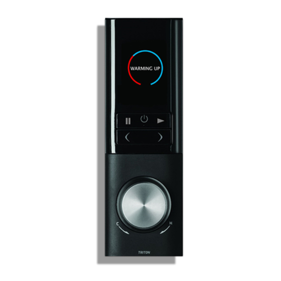
Quick Start WARMING UP ºC TO START SWITCH ON WARMING UP START SHOWER Press the Start The beep sounds when hot Press to start. Button to activate the water is available from the The target temperature warm-up cycle. source. is displayed. ºC TO START SHOWER TIMER... -
Page 31: General Maintenance
General Maintenance If the Triton Xerophyte Mixer Unit is dismantled for any reason during servicing or maintenance, then it MUST be inspected to ensure there are no leaks, it is also advised to follow the commissioning procedure to ensure no air has become trapped during the work. -
Page 32: Spare Parts
Spare Parts... - Page 33 Dual Outlet Assembly 83316920 Processor PCB 7073763 Pump Assembly 83316790 Check valve & Inlet Filter Pack 83316810 Triton Xerophyte Digital controller 83316820 Digital Controller Fixing Bracket 88316740 Data Cable Connector for Controller Only 2160634 10. Mains Cable 2160637 11. 10m Data Cable Inc Ferrite S86100820 12.
-
Page 34: Fault Diagnosis
IMPORTANT - Isolate the electricity supply before attempting any fault diagnosis inside the Triton Xerophyte Mixer Unit Cause Action/Cure Triton Xerophyte Mixer Interrupted power supply. Blown fuse or circuit breaker. Check Supply. Shower will not Renew or reset fuse or circuit breaker. - Page 35 Airlock in Triton ‘Commissioning’. Xerophyte Mixer Unit. Check and if necessary correct, see Inlet supply ‘Triton Xerophyte Mixer Unit Installation’. connection reversed. Ensure outlet pipe is thermally lagged, see Outlet pipe run is too ‘Triton Xerophyte Mixer Unit Installation’. long.
- Page 36 Wait for stored water to reach temperature. Airlock in Triton Check for correct installation, repeat Xerophyte Mixer Unit. priming to remove air from the mixing unit, see ‘Commissioning’. Check the use of flow regulators, see Combination boiler ‘Typical Suitable Installations’.
- Page 37 Diagnosis Problem/Symptom Cause Action/Cure Noise Airlock in Triton Check forcorrectinstallation, repeat Xerophyte Mixer Unit. priming to removeair from the mixing unit, see ‘Commissioning’. Water hammer. Ensure all pipework is securely fixed, see ‘General Installation Information’. Unit malfunction. Contact IWSX Customer Service.
-
Page 38: Disposal And Recycling
WEEE Directive – Policy Statement As a producer and a supplier of electric showers, Triton Showers is committed to the protection of the environment via our environmental policy and compliance with the WEEE directive. Triton Showers is fully registered with the Environment Agency under the following schemes:... -
Page 39: Guarantee, Service Policy, Etc
Should proof of purchase or the guarantee statutory rights. not be available or valid, spare parts will be charged accordingly. Triton/IWSX takes the health, safety, and wellbeing of its employees very seriously and expects customers to treat all staff What is not covered: members with respect. - Page 40 Website: iwsx.co.za Brochure enquiries: +27 (0) 12 348 5022 Triton Showers is a division of Norcros Group (Holdings) Limited. Triton Showers, Triton Road, Nuneaton, Warwickshire CV11 4NR It is our policy to improve the design and specification of our products and we reserve the right to depart from the...
Need help?
Do you have a question about the XEROPHYTE and is the answer not in the manual?
Questions and answers