Advertisement
Quick Links
Advertisement

Related Manuals for H3C A3600 Series


Summary of Contents for H3C A3600 Series
- Page 1 HP A3600 Series Ethernet Switches Installation Manual...
-
Page 2: Table Of Contents
Organization HP A3600 Series Ethernet Switches Installation Manual is organized as follows: Chapter Contents Introduces characteristics technical 1 Product Overview specifications of S3600 Series Ethernet Switches. Introduces installation preparation 2 Preparation precaution of S3600 Series Ethernet Switches. Introduces the procedures to install an S3600 Series... -
Page 3: Product Overview
Chapter 1 Product Overview 1.1 Introduction HP S3600 Series Ethernet Switches developed by HP are high-performance, high-density, easy-to-install, NMS-manageable intelligent Ethernet switches which support wire-speed Layer 2/3 switching. Table 1-1 lists the models of HP S3600 Series Ethernet Switches. Table 1-1 Models of the S3600 series Number of Number of Number of... - Page 4 and A3600-48-POE EI. The –48 VDC from the equipment room cannot be used directly. Otherwise, devices may be damaged. 1.2 A3600-24 SI 1.2.1 Front Panel I. Schematic diagram The A3600-24 SI provides twenty-four 10Base-T/100Base-TX auto-sensing Ethernet ports, four 1000Base-X SFP ports, and one Console port on the front panel, as shown in Figure 1-1.
- Page 5 Mark Status Indication Base -TX Flashing Data is being received/sent on the port. port status A 10 Mbps link is present. Yellow Flashing Data is being received/sent on the port. Flashing yellow (3 The port fails the POST. No link is present. The port is operating in full duplex mode.
- Page 6 Mark Status Indication Flashing yellow (3 The port fails the POST. The port is not connected. Flashing yellow (3 The port fails the POST. –– POST The PWR LED Displays the POST test ID (in the range of running flashes green 1 to 9).
- Page 7 Attribute Description Connection to the ASCII terminal Service Connection to the serial interface of a local terminal (a PC for example) or to a remote terminal through a pair of modems), where terminal emulation program is run V. Attributes of the 1000Base-X SFP ports The A3600-24 SI provides four 1000Base-X SFP ports (numbered from 25 to 28) on its front panel.
- Page 8 Input voltage range: 90 VAC to 264 VAC, 47 to 63 Hz 1.3 A3600-24TP SI 1.3.1 Front Panel I. Schematic diagram The A3600-24TP SI provides twenty-four 10Base-T/100Base-TX auto-sensing Ethernet ports, two 1000Base-X SFP ports, two 10/100/1000Base-T auto-sensing Ethernet ports, and one Console port on the front panel, as shown in Figure 1-3. (1) 10Base-T/100Base-TX auto-sensing Ethernet port status LEDs (2) 1000Base-X SFP port status LEDs (3) 10/100/1000Base-T auto-sensing Ethernet port status LEDs...
- Page 9 Mark Status Indication Duplex information of 10Base-T/100Base- TX Ethernet ports, and 1000Base-X SFP Duplex Solid yellow ports. A 100 Mbps link is present. Green Flashing Data is being received/sent on the port. A 10 Mbps link is present. Yellow Speed Flashing Data is being received/sent on the port.
- Page 10 Mark Status Indication The port is operating in half duplex mode. Yellow Flashing Data is being received/sent on the port Flashing yellow The port fails POST. (3Hz) No data is being received/sent on the port. POST The PWR LED Displays the POST test ID (in the range of 1 running flashes green to 9).
- Page 11 Attribute Description 10/100 Mbps, half duplex/full duplex Rate 1000 Mbps, full duplex MDI/MDI-X auto-sensing IEEE 802.3u Standard IEEE 802.3ab Transmission distance over the 100 m (328.08 ft) over the category-5 unshielded twisted pair (UTP) selected medium cable VI.
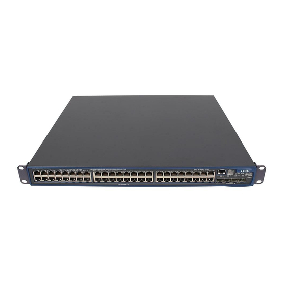
- Page 12 (1) 10Base-T/!00Base-TX auto-sensing Ethernet port status LEDs (2) Console port (3) 7-segment digital LED (4) Mode button (5) Mode LED (6) AC power LED (7) 1000Base-X SFP port status LEDs Figure 1-5 Front panel of the A3600-48 SI II. LEDs On the front panel, the A3600-48 SI provides one AC power LED, one mode LED, one 7-segment digital LED, forty-eight 10Base-T/100Base-TX Ethernet port status LEDs, and four 1000Base-X SFP port status LEDs.
- Page 13 Note: The types of 1000Base-X SFP modules may be subject to changes without notice. Consult HP marketing personnel or technical support personnel to obtain the latest information about SFP modules. For specifications of SFP modules, refer to HP Low End Series Ethernet Switches Pluggable Modules Manual.
- Page 14 (2) 1000Base-X SFP port status LEDs (3) Console port (4) 7-segment digital LED (5) DC power LED (6) AC power LED (7) Mode LED (8) Mode button Figure 1-7 Front panel of the A3600-24 EI II. LEDs On the front panel, the A3600-24 EI provides one AC power LED, one DC power LED, one mode LED, one 7-segment digital LED, twenty-four 10Base-X/100Base-TX auto-sensing Ethernet port status LEDs, and four 1000Base-X SFP port status LEDs.
- Page 15 Mark Status Indication A 10 Mbps link is present. Yellow Flash Data is being received/sent on the port Flashing yellow (3 The port fails POST. No link is present. The port is operating in full duplex mode. Green Flash Data is being received/sent on the port The port is operating in half duplex mode.
- Page 16 Mark Status Indication Flashing yellow (3 The port fails to pass POST. The port is not connected. Flashing yellow (3 The port fails a POST. PoE mode –– III. Attributes of the 10Base-T/100Base-TX Ethernet ports See Table 1-3. IV. Console port The A3600-24 EI provides one EIA/TIA-232 compliant Console port for local or remote switch configuration.
- Page 17 DC power Rated voltage range: –48 VDC to –60 VDC Input voltage range: –36 VDC to –72 VDC 1.6 A3600-24-SFP EI 1.6.1 Front Panel I. Schematic diagram On the front panel, the A3600-24-SFP EI provides twenty-four 100Base-X SFP ports, two 1000Base-X SFP ports, two 10/100/1000Base-T auto-sensing Ethernet ports, and one Console port, as shown in Figure 1-9.
- Page 18 Mark Color Indicates Duplex information of 10Base- T/100Base-TX Ethernet ports and Duplex Solid yellow the 1000Base-X SFP ports. POST The PWR LED Flashes the POST test ID of the running flashes green. failed test. The PWR LED POST test ID of the failed test. flashes yellow.
- Page 19 Mark Color Indicates The port is connected, and the device is in an IRF loop fabric. Green Data is being received/sent on the Flash port The port is connected, and the device is in an IRF chain fabric. Yellow Speed Data is being received/sent on the Flash port...
- Page 20 Mark Color Indicates The port is connected, and the device is in an IRF loop fabric. Green Data is being received/sent on the Flash port The port is connected, and the device is in an IRF chain fabric. Yellow Speed Data is being received/sent on the Flash port...
- Page 21 Note: The types of 1000Base-X SFP modules may be subject to changes without notice. Consult HP marketing personnel or technical support personnel to obtain the latest information about SFP modules. For specifications of SFP modules, refer to HP Low End Series Ethernet Switches Pluggable Modules Manual.
- Page 22 (1) 10Base-T/100Base-TX auto-sensing Ethernet port status LEDs (2) Console port (3) 7-segment digital LED (4) Mode button (5) Mode LED (6) AC Power LED (7) DC power LED (8) 1000Base-X SFP port status LED Figure 1-11 Front panel of the A3600-48 EI II.
- Page 23 The A3600-48 EI provides an AC power socket, a DC power socket, and a grounding screw on the rear panel, as shown in Figure 1-12. (1) AC power socket (2) DC power socket (3) Grounding screw Figure 1-12 Rear panel of the A3600-48 EI II.
- Page 24 Table 1-12 LEDs on the front panel of the A3600-24-POE SI/A3600-24-POE EI Mark Color Indicates The system passes a POST and is Solid green operating normally. The system is running a POST or is Flashing green (1 Hz) downloading software. AC Power The POST of the system fails or a Solid red...
- Page 25 Mark Color Indicates Flash Data is being received/sent on the port The port is operating in half duplex mode Yellow Flash Data is being received/sent on the port Flashing yellow (3 Hz) The port fails POST. No data is being received/sent on the port Solid green The port is providing power...
- Page 26 Mark Color Indicates No data is being received/sent Flashing yellow (3 Hz) The port fails POST. III. Attributes of the 10Base-T/100Base-TX Ethernet ports Table 1-13 Attributes of the 10Base-T/100Base-TX Ethernet ports Attribute Description Connector RJ-45 Number of ports 10/100 Mbps, half duplex/full duplex ...
- Page 27 The A3600-24-POE SI/A3600-24-POE EI provides an AC power socket, a DC power socket and a grounding screw on its rear panel, as shown in Figure 1-14. (1) AC power socket (2) DC power socket (3) Grounding screw Figure 1-14 Rear panel of the A3600-24-POE SI/A3600-24-POE EI II.
- Page 28 (3) 7-segment digital LED (4) Mode button (5) Mode LED (6) AC Power LED (7) DC power LED (8) 1000Base-X SFP port status LED Figure 1-15 Front panel of the A3600-48-POE SI/A3600-48-POE EI II. LEDs The A3600-48-POE SI/A3600-48-POE EI provides one AC power LED, one DC power LED, one mode LED, one 7-segment digital LED, forty-eight 10Base-T/100Base-TX auto-sensing Ethernet port status LEDs, and four 1000Base-X SFP port status LEDs.
- Page 29 The A3600-48-POE SI/A3600-48-POE EI provides one EIA/TIA-232 compliant Console port for local or remote switch configuration. For the attributes, see Table 1-4. 1.9.2 Rear Panel I. Schematic diagram The A3600-48-POE SI/A3600-48-POE EI provides an AC power socket, a DC power socket and a grounding screw on the rear panel, as shown in Figure 1-16.
- Page 30 Item A3600-24 SI A3600-24TP SI A3600-48 SI AC power input Power system Rated voltage range: 100 VAC to 240V AC, 50 Hz/60 Hz Input voltage range: 90 VAC to 264 VAC, 47 Hz/63 Hz PoE (as a powered Not supported Not supported Not supported device)
-
Page 31: Preparation
A3600-24-POE SI A3600-48-POE SI Item A3600-24-POE EI A3600-48-POE EI Physical dimensions (H × W 43.6 × 440 × 420 (1.7 × 17.3 × 16.5 in) × D) Weight 5.8 kg (12.8 lb) 6.2 kg (13.7 lb) 24 × 10Base-T/100Base-TX 48 × 10Base-T/100Base-TX Ethernet Ethernet ports ports Number of fixed ports... - Page 32 2.2 Installation Site The S3600 series must be used indoors. You can mount your switch in a rack or on a desktop/workbench, but make sure: Adequate clearance is reserved at the air inlet/exhaust vents for ventilation. The rack or desk has a good ventilation system. ...
-
Page 33: Installation
Use electromagnetic shielding when necessary, for example, use shielded interface cables. Route interface cables only indoors to prevent signal ports from getting damaged by over-voltage or over-current caused by lightning strikes. 2.2.4 Laser Safety The S3600 series are class-1 laser devices. If the extended optical boards on your switch are operating, do not stare into the optical ports because the laser light emitted by the optical fiber can hurt your retina. - Page 34 Table 3-1 Installation methods for a switch with a width of 440 mm (17.3 in) Method Use front Use front Use front Use front and rear mounting ears and mounting ears and mounting ears mounting ears a tray guide rails Depth √...
- Page 35 (1): Screw hole used to fix the mounting ear to the cabinet (Use one M6 screw) Figure 3-2 Appearance of a rear mounting ear When you install S3600 series into 19” standard cabinets, you should select front and rear mounting ears listed in Table 3-2. Table 3-2 Selection of mounting ears for the S3600 series Configuration type Configuration type...
- Page 36 Figure 3-4 Fix front mounting ears (2) III. Use front mounting ears and a tray Follow these steps to install a switch into a 19-inch standard cabinet: Wear an ESD-preventive wrist strap and check the grounding and stability of the cabinet. Fix the delivered tray horizontally in a proper position.
- Page 37 Figure 3-5 Fix front mounting ears and load-bearing screws Note: There are three positions to mount a load-bearing screw on both sides of a switch. You should select a proper position according to the actual requirements. The rear mounting ears tightly contacted with the load-bearing screws can support the switch.
- Page 38 Screw 2: Used to fix rear mounting ears to rear brackets Figure 3-7 Fix front and rear mounting ears After the switch is pushed into the cabinet, ensure that the upper edge of rear mounting ears is tightly contacted with the load- bearing screw, as shown in Figure 3-8.
- Page 39 Figure 3-10 shows the appearance of a guide rail. Slotted hole 1: Used to fix the guide rail to the rear bracket. You can adjust the screw hole position according to the position of the switch. Cooling hole: Used for heat dissipation between switch and cabinet Slotted hole 2: Used to fix the guide rail to the front bracket Figure 3-10 Appearance of a guide rail ...
- Page 40 Hold the two sides of the switch and slide it gently along the guide rails into the cabinet until it is located in a proper position, as shown in Figure 3-12. Ensure that the bottom side of the guide rails and the switch are in close contact. Figure 3-12 Install front mounting ears and guide rails Fix the other end of front mounting ears to the front brackets of the cabinet with M6 screws and captive nuts and ensure that the front mounting ears and guide rails have fixed the switch in the cabinet securely, as shown in Figure 3-13.
- Page 41 Allow 10 cm (3.9 in.) of clearance around the sides of the chassis. Do not place heavy objects on the switch. 3.2 Connecting the Power Cord and the Ground Wire 3.2.1 Connecting the AC Power Cord I. AC power socket (recommended) You are recommended to use a single-phase three-line power socket with a ground contact or a general purpose PC power socket, making sure that the power point is well connected to building ground.
- Page 42 Step 2: Connect DC socket. Figure 3-16 RPS DC connector As shown in Figure 3-16, first insert two cables into the appropriate holes through dust-proof shield, and then fix the cables separately by using screws 1 and 2. Make sure that the positive and negative ends of the cable are inserted appropriately and accord with silkscreen on the holes.
- Page 43 3.2.3 Connecting the Ground Wire Caution: Correctly connecting the switch ground wire is crucial to the lightning protection and electromagnetic susceptibility (EMS) of a switch. The power input end of the switch is connected with a noise filter, whose central ground is directly connected to the chassis, forming the chassis ground (commonly known as PGND).
- Page 44 (1) AC-input (2) Grounding screw (3) Power transformer (4) PE wire (5) AC-input (with 3-wire cable) (6) Ethernet switch Figure 3-20 Grounding through the AC PE wire For a DC-powered switch, if none of the first two conditions is available, ground it through the return wire (RTN) of the DC power supply.
- Page 45 After a switch starts, the PON interface may emit invisible radial when there is no optical connector connected to it and the protective cap is removed from it. Therefore, do not stare into the optical interface. Be sure to cover the protective cap within 10 seconds if an optical connector is not in use to keep the optical connector clean.
- Page 46 Caution: Read the mark for the port to be connected carefully to make sure it is the right port. Note: The serial ports on PCs do not support hot swapping. Therefore, do not insert or remove a serial interface cable from a PC that is connected to a switch with power.
-
Page 47: Starting Up The Switch At The Initial Boot
3.6 Verifying Installation The correct power source is used. The ground wire is securely connected. Both of the console cable and power cord are correctly connected. All the interface cables are routed indoors. If there are cables outdoors, check that the socket strip with lightning protection and lightning arresters for network ports have been correctly connected. - Page 48 Step 1: Start the PC and select [Start/Programs/Accessories/Communications/HyperTerminal]. The HyperTerminal window displays the Connection Description dialog box, as shown in Figure 4-2. Figure 4-2 Setting up a new connection Step 2: Enter the name of the new connection in the Name field and click <OK>. The dialog box, as shown in Figure 4-3 displays.
- Page 49 Figure 4-4 Setting communications parameters Step 4: Click <OK>. The HyperTerminal dialogue box appears, as shown in Figure 4-5. Figure 4-5 HyperTerminal window In the HyperTerminal dialogue box, select [File/Properties]. The Properties dialog box appears. In the Properties dialog box, select the Settings tab, as shown in Figure 4-6.
- Page 50 Figure 4-6 Settings tab 4.4 Booting the Switch 4.4.1 Verifying Installation before Power-up Before powering up the switch, check that: Both the power cord and the grounding wire are correctly connected. Proper power supply is used. The console cable is correctly connected. ...
- Page 51 CPU Clock Speed : 200MHz BUS Clock Speed : 33MHz Memory Size : 64MB Mac Address : 000fcb004500 Press Ctrl-B to enter Boot Menu... 1 By default, the system boots with fast startup mode. If you do not want to change it, ignore the message “Press Ctrl-B to Enter Boot Menu…”, the system boots automatically without entering the Boot Menu one seconds later and displays the following information: Auto-booting...
- Page 52 Are you sure to change it to full startup mode? Yes or No(Y/N) Make sure you already understand that it takes a relative long time for the system to boot with full startup mode because it must perform some self-test operations. Press <Y>.
- Page 53 Press Ctrl-B to enter Boot Menu... 5 To enter the Boot Menu, press <Ctrl+B> within five seconds after the message “Press Ctrl-B to enter Boot Menu... 5” appears. If not, the system automatically boots and displays: Auto-booting... Decompress Image............................................
-
Page 54: Loading Boot Rom And Host Software
Chapter 5 Loading Boot ROM and Host Software Switch software loading through serial ports in the past is time consuming and cannot be operated remotely. To address these problems, TFTP and FTP are used to allow software and file downloading through Ethernet ports. The following subsections describe how to load software and files in these two approaches. - Page 55 Operations of a file are separate from those of the attributes. For example, when you delete a main boot file from the Flash, the main attribute of the file remains. If you download a valid file with the same name to the Flash, the new file will have the main attribute.
- Page 56 Enter your choice(0-9):2 Select application file to boot 1. set application files 2. set configuration files 3. set web files 0. return Enter your choice(0-3):1 II. Set the attributes of application, configuration, or Web files as needed. In this example, enter 1 to select “1. set application files”. File Number File Size(bytes) File Name...
- Page 57 If your terminal is directly connected to the switch, you can load Boot ROM and host software locally. But before that, make sure they are correctly connected. Note: The steps that you should take to load Boot ROM program and host software are the same, except that during Boot ROM program loading you need to press <Ctrl +U>...
- Page 58 1. Download application file to flash 2. Select application file to boot 3. Display all files in flash 4. Delete file from flash 5. Modify bootrom password 6. Enter bootrom upgrade menu 7. Skip current configuration file 8. Set bootrom password recovery 9.
- Page 59 Enter your choice (0-5): Step 3: Choose an appropriate download baud rate. Enter <5> for example to download at 115200 bps. The system displays the following information: Download baudrate is 115200 bps Please change the terminal's baudrate to 115200 bps and select XMODEM protocol Press enter key when ready ...
- Page 60 Figure 5-2 Console Port Configuration dialog box Step 5: Click <Disconnect> to disconnect the HyperTerminal from the switch and then click <Call> to re-establish the connection, thus validating the baud rate setting. Figure 5-3 <Disconnect> and <Call> buttons Note: After changing terminal’s baud rate, you must disconnect and connect the terminal emulation program to validate the new configuration.
- Page 61 Figure 5-4 Send File dialog box Step 8: Click <Send>. The system displays Figure 5-5. Figure 5-5 Sending File interface Step 9: After completing loading, the system displays the following information: Loading ...CCCCCCCCCC done! Note: You do not need to reset the HyperTerminal’s baud rate and can skip the last step if you have chosen 9600 bps. In this case, the system does not display the above prompt message but “BootROM is updating now........done!”...
- Page 62 Enter your choice(0-3):3 Select <3>. The subsequent steps are the same as those for loading Boot ROM, except for the program to be downloaded in prompt messages. 5.3.3 Loading Software from an Ethernet Port Using TFTP I. Introduction to TFTP Trivial File Transfer Protocol is a TCP/IP protocol used for file transfer between clients and servers.
- Page 63 Step 1: Select <1> in the Boot Menu. The system displays the following information: 1. Set TFTP protocol parameter 2. Set FTP protocol parameter 3. Set XMODEM protocol parameter 0. Return to boot menu Enter your choice(0-3):3 Select <1>. The subsequent steps are the same as those for loading Boot ROM, except for the program to be downloaded in prompt messages.
- Page 64 Bootrom updating..done! III. Loading host software Follow these steps to download host software: Step 1: Select <1> in the Boot Menu. The system displays: 1. Set TFTP protocol parameter 2. Set FTP protocol parameter 3. Set XMODEM protocol parameter 0. Return to boot menu Enter your choice(0-3):3 Select <2>.
-
Page 65: Maintenance And Troubleshooting
The app to boot at the next time is: flash:/SWITCH.bin <HP> reboot Note: Power disconnection must be prevented during the loading process. The configurations that you just make cannot survive a reboot. Make sure you have saved them before you have the system reboot. - Page 66 2. Select application file to boot 3. Display all files in flash 4. Delete file from flash 5. Modify bootrom password 6. Enter bootrom upgrade menu 7. Skip current configuration file 8. Set bootrom password recovery 9. Set switch startup mode 0.
- Page 67 Reconfigure the parameters if their values are different. 02-Appendix Table of Contents Appendix A Lightning Protection of the Switch A.1 Installation of Lightning Arrester for AC Power (Socket Strip with Lightning Protection) A.2 Installation of Lightning Arrester for Network Port Appendix A Lightning Protection of the Switch A.1 Installation of Lightning Arrester for AC...
- Page 68 Make sure that the arrester is well grounded before using the lightning arrester for power. After inserting AC power cord plug of switch into the socket of lightning arrester, if the green LED is on and the red LED does not alarm, it means that the lightning arrester of power is running and the function of lightning protection has taken effect.
- Page 69 Note: The instruction of lightning arrester for network port contains the technical specifications, installation and maintenance guide of the arrester. Please carefully read it before installing the arrester. Step 5: Use the nylon ties to bundle the cables neatly. Figure A-2 Installation diagram of lightning arrester for network port III.
Need help?
Do you have a question about the A3600 Series and is the answer not in the manual?
Questions and answers