H3C S9820-64H Manual
Hide thumbs
Also See for S9820-64H:
- Installation manual (55 pages) ,
- Installation, quick start (4 pages) ,
- Manual (39 pages)

Related Manuals for H3C S9820-64H


Summary of Contents for H3C S9820-64H
- Page 1 H3C S9820-64H Switch Hardware Information and Specifications New H3C Technologies Co., Ltd. http://www.h3c.com Document version: 6W101-20230126...
- Page 2 The information in this document is subject to change without notice. All contents in this document, including statements, information, and recommendations, are believed to be accurate, but they are presented without warranty of any kind, express or implied. H3C shall not be liable for technical or editorial errors or omissions contained herein.
- Page 3 Preface H3C S9820-64H Switch Hardware Information and Specifications describes the product models, technical specifications, removable components, ports, LEDs, and cooling system of the S9820-64H switch. This preface includes the following topics about the documentation: • Audience. • Conventions. • Documentation feedback.
- Page 4 Convention Description Folder. Symbols Convention Description An alert that calls attention to important information that if not understood or followed can result in personal injury. WARNING! An alert that calls attention to important information that if not understood or followed can result in data loss, data corruption, or damage to hardware or software.
- Page 5 It is normal that the port numbers, sample output, screenshots, and other information in the examples differ from what you have on your device. Documentation feedback You can e-mail your comments about product documentation to info@h3c.com. We appreciate your comments.
-
Page 6: Table Of Contents
Contents 1 Product model and technical specifications ································ ············· 1-2 Product model ················································································································································· 1-2 Technical specifications ·································································································································· 1-2 2 Chassis views ································ ································ ·························· 3 Removable components ································ ································ ·········· 3-6 Power supplies ················································································································································ 3-6 Fan trays ························································································································································· 3-7 4 Ports and LEDs································ ································... -
Page 7: Product Model And Technical Specifications
The S9820-64H switch model is available with multiple product codes. To identify the product code of your switch, use the product barcode on its rear panel. The S9820-64H switch model is available with the LS-9820-64H or LS-9820-64H-H1 product code. If the switch is referred to as the S9820-64H switch, the information applies to the S9820-64H switch with either of the codes. - Page 8 Item S9820-64H • Triple AC inputs: 349 W (For the power consumption data collection standard, see Table1-2) • Quadruple AC inputs: 365 W • Dual DC inputs: 329 W Triple DC inputs: 338 W • • Quadruple DC inputs: 352 W •...
-
Page 9: Chassis Views
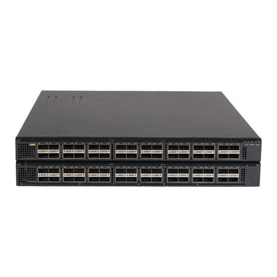
Chassis views Figure2-1 S9820-64H front panel (1) QSFP28 port (2) QSFP28 port LED Figure2-2 S9820-64H rear panel (1) Serial console port (2) Mini USB console port (3) USB port (4) System status LED (SYS) (5) Fan tray 1 (6) Fan tray 2... - Page 10 In Figure2-2, LSWM1BFANSC fan trays are installed in the three fan tray slots. The switch supports shipping with fan trays and power supplies installed. To purchase a switch preinstalled with fans trays and power supplies, contact marketing staff. Figure2-3 S9820-64H left panel (1) Primary grounding point (2) Auxiliary grounding point...
-
Page 11: Removable Components
Remarks • Rated AC input voltage: 100 VAC to 240 For more information about the VAC @ 50 Hz or 60 Hz power supplies, see H3C • Max AC input voltage: 90 VAC to 264 LSVM1AC650 LSVM1AC650 & VAC @ 47 Hz to 63 Hz LSVM1DC650 Power Modules •... -
Page 12: Fan Trays
120 CFM (3.40 m /min) tray panel) • LSWM1BFANSCB/ Maximum power 57 W consumption LSWM1BFANSCB- SN (air exhaust on H3C LSWM1BFANSC & LSWM1BFANSCB Fan Trays User fan tray panel) Documentation Guide reference H3C LSWM1BFANSC-SN & LSWM1BFANSCB-SN Fan Trays User Guide... -
Page 13: Ports And Leds
As a best practice, use H3C transceiver modules and cables for the switch. H3C transceiver modules and cables are subject to change over time. For the most up-to-date list of H3C transceiver modules and cables, contact H3C Support or marketing staff. -
Page 14: Fe Sfp Modules
Item Specification Functions and services Software upgrade and network management. FE SFP modules Table4-3 FE SFP transceiver modules available for the SFP management port FE SFP transceiver Central Fiber type and Connector transmission module wavelength (nm) diameter (µm) distance Multi-mode, 50/125 SFP-FE-SX-MM1310-A 1310 2 km (1.24 miles) -
Page 15: Usb Port
2.0. NOTE: USB devices from different vendors vary in compatibilities and drivers. H3C does not guarantee correct operation of USB devices from other vendors on the switch. If a USB device fails to operate on the switch, replace it with one from another vendor. - Page 16 QSFP28 Central Modal Maximum Fiber type and transceiver wavelength Connector bandwidth transmission diameter (µm) module (nm) (MHz*km) distance 9/125 PSM4-SM13 polished, 12-fiber) Four lanes: • 1271 QSFP-100G- Single-mode, CWDM4-SM1 • 1291 2 km (1.24 miles) 9/125 300-A • 1311 • 1331 Four lanes: •...
- Page 17 Table4-7 QSFP28 fiber cables available for the QSFP28 ports QSFP28 fiber cable Cable length QSFP-100G-D-AOC-7M 7 m (22.97 ft) QSFP-100G-D-AOC-10M 10 m (32.81 ft) QSFP-100G-D-AOC-20M 20 m (65.62 ft) Table4-8 QSFP28 to SFP28 copper cables available for the QSFP28 ports QSFP28 to SFP28 copper cable Cable length QSFP-100G-4SFP-25G-CAB-1M...
- Page 18 Fiber type QSFP+ Central Modal transceiver wavelength Connector bandwidth transmission diameter module (nm) (MHz × km) distance (µm) • 1291 • 1311 • 1331 Table4-10 QSFP+ copper cables available for the QSFP28 ports QSFP+ copper cable Max transmission distance LSWM1QSTK0 1 m (3.28 ft) LSWM1QSTK1 3 m (9.84 ft)
-
Page 19: Leds
LEDs System status LED The system status LED shows the operating status of the switch. Table4-13 System status LED description LED mark Status Description Steady green The switch is operating correctly. Flashing green The switch is performing power-on self test (POST). Steady red The system has failed to pass POST or a fault has occurred. -
Page 20: Fan Tray Alarm Leds
Fan tray alarm LEDs The LSWM1BFANSC, LSWM1BFANSC-SN, LSWM1BFANSCB, and LSWM1BFANSCB-SN fan trays each provide an alarm LED. Table4-16 Description for the alarm LED Status Description The fan tray is faulty. The fan tray is operating correctly or no power is present. Cooling system CAUTION: The chassis and power supplies use separate air aisles. - Page 21 Figure5-2 Airflow from the port side to the power supply side (with LSWM1BFANSCB/LSWM1BFANSCB-SN fan trays) 5-16...
Need help?
Do you have a question about the S9820-64H and is the answer not in the manual?
Questions and answers